EP2022323B1 - Transplantoir - Google Patents
Transplantoir Download PDFInfo
- Publication number
- EP2022323B1 EP2022323B1 EP08161764A EP08161764A EP2022323B1 EP 2022323 B1 EP2022323 B1 EP 2022323B1 EP 08161764 A EP08161764 A EP 08161764A EP 08161764 A EP08161764 A EP 08161764A EP 2022323 B1 EP2022323 B1 EP 2022323B1
- Authority
- EP
- European Patent Office
- Prior art keywords
- seedlings
- tray
- spears
- extraction
- pair
- Prior art date
- Legal status (The legal status is an assumption and is not a legal conclusion. Google has not performed a legal analysis and makes no representation as to the accuracy of the status listed.)
- Not-in-force
Links
- 230000007246 mechanism Effects 0.000 claims description 51
- 238000000605 extraction Methods 0.000 claims description 48
- 238000012546 transfer Methods 0.000 claims description 28
- 238000000926 separation method Methods 0.000 claims description 11
- 238000007599 discharging Methods 0.000 claims description 9
- 238000000034 method Methods 0.000 claims description 8
- 239000000284 extract Substances 0.000 claims description 2
- 239000002184 metal Substances 0.000 description 7
- 229910052751 metal Inorganic materials 0.000 description 7
- 239000002689 soil Substances 0.000 description 6
- 230000000712 assembly Effects 0.000 description 5
- 238000000429 assembly Methods 0.000 description 5
- 238000013461 design Methods 0.000 description 5
- 230000002093 peripheral effect Effects 0.000 description 5
- 238000013459 approach Methods 0.000 description 4
- 230000003750 conditioning effect Effects 0.000 description 3
- 230000002950 deficient Effects 0.000 description 3
- 238000007689 inspection Methods 0.000 description 3
- 239000004743 Polypropylene Substances 0.000 description 2
- 229910000746 Structural steel Inorganic materials 0.000 description 2
- 238000010276 construction Methods 0.000 description 2
- 238000012937 correction Methods 0.000 description 2
- -1 polypropylene Polymers 0.000 description 2
- 229920001155 polypropylene Polymers 0.000 description 2
- 239000003516 soil conditioner Substances 0.000 description 2
- 125000006850 spacer group Chemical group 0.000 description 2
- 238000005452 bending Methods 0.000 description 1
- 230000000739 chaotic effect Effects 0.000 description 1
- 230000006835 compression Effects 0.000 description 1
- 238000007906 compression Methods 0.000 description 1
- 230000001186 cumulative effect Effects 0.000 description 1
- 230000005484 gravity Effects 0.000 description 1
- 229920001903 high density polyethylene Polymers 0.000 description 1
- 239000004700 high-density polyethylene Substances 0.000 description 1
- 239000000463 material Substances 0.000 description 1
- 230000003287 optical effect Effects 0.000 description 1
- 239000004033 plastic Substances 0.000 description 1
- 229920003023 plastic Polymers 0.000 description 1
- 230000000750 progressive effect Effects 0.000 description 1
- 230000003014 reinforcing effect Effects 0.000 description 1
- 230000001960 triggered effect Effects 0.000 description 1
- XLYOFNOQVPJJNP-UHFFFAOYSA-N water Substances O XLYOFNOQVPJJNP-UHFFFAOYSA-N 0.000 description 1
Images
















Classifications
-
- A—HUMAN NECESSITIES
- A01—AGRICULTURE; FORESTRY; ANIMAL HUSBANDRY; HUNTING; TRAPPING; FISHING
- A01G—HORTICULTURE; CULTIVATION OF VEGETABLES, FLOWERS, RICE, FRUIT, VINES, HOPS OR SEAWEED; FORESTRY; WATERING
- A01G9/00—Cultivation in receptacles, forcing-frames or greenhouses; Edging for beds, lawn or the like
- A01G9/02—Receptacles, e.g. flower-pots or boxes; Glasses for cultivating flowers
- A01G9/029—Receptacles for seedlings
- A01G9/0299—Handling or transporting of soil blocks or seedlings
-
- A—HUMAN NECESSITIES
- A01—AGRICULTURE; FORESTRY; ANIMAL HUSBANDRY; HUNTING; TRAPPING; FISHING
- A01C—PLANTING; SOWING; FERTILISING
- A01C11/00—Transplanting machines
- A01C11/02—Transplanting machines for seedlings
- A01C11/025—Transplanting machines using seedling trays; Devices for removing the seedlings from the trays
-
- Y—GENERAL TAGGING OF NEW TECHNOLOGICAL DEVELOPMENTS; GENERAL TAGGING OF CROSS-SECTIONAL TECHNOLOGIES SPANNING OVER SEVERAL SECTIONS OF THE IPC; TECHNICAL SUBJECTS COVERED BY FORMER USPC CROSS-REFERENCE ART COLLECTIONS [XRACs] AND DIGESTS
- Y10—TECHNICAL SUBJECTS COVERED BY FORMER USPC
- Y10S—TECHNICAL SUBJECTS COVERED BY FORMER USPC CROSS-REFERENCE ART COLLECTIONS [XRACs] AND DIGESTS
- Y10S111/00—Planting
- Y10S111/90—Methods of planting seeds and miscellaneous compositions
-
- Y—GENERAL TAGGING OF NEW TECHNOLOGICAL DEVELOPMENTS; GENERAL TAGGING OF CROSS-SECTIONAL TECHNOLOGIES SPANNING OVER SEVERAL SECTIONS OF THE IPC; TECHNICAL SUBJECTS COVERED BY FORMER USPC CROSS-REFERENCE ART COLLECTIONS [XRACs] AND DIGESTS
- Y10—TECHNICAL SUBJECTS COVERED BY FORMER USPC
- Y10S—TECHNICAL SUBJECTS COVERED BY FORMER USPC CROSS-REFERENCE ART COLLECTIONS [XRACs] AND DIGESTS
- Y10S111/00—Planting
- Y10S111/919—Special transplant related feature
Definitions
- the present invention relates generally to transplanters, and more particularly to one which can avoid skips when planting which may occur when seeds in a tray row fail to grow into seedlings. This is accomplished by picking up an entire row of seedlings from a tray, transferring the seedlings to a mechanism which eliminates gaps between seedlings, and then discharging the seedlings one at time to the ground with a desired spacing between the seedlings.
- the plants are then discharged, one at a time, into a series of interlocks that convey the plants to the ground engaging row unit.
- three separate sets of sensors look for plant skips and advance the root ball chamber belt assembly one cell to make up for skips and eject the deficient root ball at the same time.
- US Patent No. 6,080,951 discloses another approach to overcome the seedling tray skip problem.
- This concept utilizes a system, whereby two sets of plungers and extractors remove plants simultaneously from a plant tray. On a ten cell tray, the first extractor would be positioned at the No. 1 cell and the second at the No. 6 cell. After extraction, the plants are dropped into two separate gated chambers and sensors confirm that plants are present. In normal operation, the plants would discharge sequentially from each chamber. If a skip is detected, the deficient root ball would be discarded and the other root ball would be planted in its place.
- the method includes the steps of picking up an entire row of seedlings from a tray, which row may have gaps between seedlings, transferring the seedlings to a mechanism which eliminates gaps between seedlings, and then discharging the seedlings one at time to the ground with a desired spacing between the seedlings.
- the seedlings have a rootball, stem, and leaves or foliage.
- a further object of the present invention is to provide a nursery tray indexing mechanism for use in a transplanter which discharges seedlings one at time to the ground with a desired spacing between the seedlings, which transplanter picks up an entire row of seedlings from a tray, which indexing mechanism is capable of receiving nursery trays of differing depths, widths, lengths and spacings between adjacent rows of cells, the indexing mechanism having top and bottom holding rails for slidably receiving and holding nursery trays; means for indexing the tray a distance approximately the width of a nursery tray cell; and means to finally position the tray by engaging a cell.
- a spear device To extract a row of plants, a spear device is utilized which penetrates across the top of the tray, capturing a row of plants by their stems. A bladder tube is then inflated, pinching the stems between the spears. With the tray in a vertical position, the spear extracts one row of plants and rotates down. This concept eliminates the need to engage the tray, thereby eliminating unnecessary sophistication and accuracy needed in the plunger type concept. Extracting the plants by gripping the stems and leaves of a root ball is much less invasive to the root ball, whereas the plunger concept compresses and damages the end of the root ball extensively. With the spear extraction concept, all the deficient root balls are left in the tray.
- the row of inverted plants is placed on a pair of gap-up belts that run faster than the discharge rate, thereby pushing up any skips in the row of plants.
- No electronics and no sensors are needed in this configuration, thereby increasing the accuracy and reducing any unnecessary sophistication of the system.
- right hand and left hand reference is determined by standing behind the transplanter and facing its direction of travel.
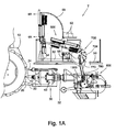
- front and rear references are applicable to a single row transplanter as shown in FIG. 1A .
- the transplanter of this invention is indicated generally at "T" in FIG. 1 . It may be semi-integrally mounted on the three point hitch 20, 22, 24 of a tractor 10, only a portion of which is shown in FIG. 1 .
- a box-like subframe indicated generally at 30 is in turn carried by the three point hitch.
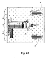
- Mounted on the back of the subframe 30 is a tool bar 32 which in turn carries wheels 34, 36 shown only in FIG. 2A .
- Each of the wheels is carried by a pivoted sub-frame (not shown) which is in turn pivotally secured to the tool bar.
- Each of the wheels may be moved up and down. As this design is conventional, it is not illustrated.
- high volume air compressor indicated generally at 40 and also, but not shown, a high pressure air compressor, a 24 volt alternator, and a 24 volt battery source, the compressors and alternator being powered by the PTO shaft 42 of the tractor.
- the air discharged by the air high pressure compressor provides the power required by the various air motors on the transplanter, and the air from the high volume compressor is used by air knifes and to assist flow through the drop tube.
- the transplanter includes an operator support or platform 50.
- a horizontal transplanter subframe 52 is mounted on the operator support 50.
- This in turn carries front and rear vertical subframe assemblies indicated generally at 54 and 56, respectively.
- An arched subframe 58 extends from the top of the vertical subframe 54 downwardly and to the back to a location in front of the rear vertical subframe 56.
- the arched subframe 58 carries many air lines and electrical controls shown generally at 60 in FIG. 2A .
- control modules 62 may be mounted on the subframe 58.
- a high pressure air reservoir and a low pressure air manifold 66 are carried below the platform 50.
- the transplanter consists of several major subassemblies.
- a first major subassembly is the tray indexing mechanism which is indicated generally at 100 and which is best illustrated in FIGS. 3A to 3J .
- the subassembly for picking up an entire row of seedlings from a tray is indicated generally at 300, and is best illustrated in FIGS. 4A to 8 .
- the subassembly which eliminates gaps between seedlings is indicated generally at 500 and is best illustrated in FIGS. 8 to 12B , and consists of a seedling loader group, continuously running gap-up belts, a cut-off gate and a gap-up root-ball pincher.
- the planter assembly which plants individual seedlings in the ground, includes a planter frame subassembly indicated generally at 800, which frame subassembly supports furrow opening and closing mechanisms.
- the planter assembly further includes a plant feeder subassembly indicated generally at 1300.
- FIG. 2B illustrates a three row version
- FIG. 2A illustrates a single row version
- the three row version does not differ significantly from the two row version, except that the operators support platform is larger.
- the tray indexing mechanism, the subassembly for picking up an entire row of seedlings from a tray, and the subassembly which eliminates gaps between seedlings, and for sending the seedlings into a drop tube are reversed in the center row unit.
- the planter subassembly in the center row unit not shown, is not reversed.
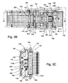
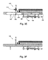
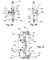
- the tray indexing mechanism is best shown in FIGS. 3A-3H .
- the tray indexing mechanism which is indicated generally at 100, should be adjustable to accommodate trays of differing widths, etc.
- the indexing mechanism is carried by the vertical subframe 54 which includes a pair of vertically extending spaced apart angle iron frame members 106, 108.
- the indexing mechanism is provided with horizontal tray holding rails 102, 104.
- the top tray holding rail 102 is secured to the top of the frame members 106 and 108 by suitable fasteners 110.
- the bottom rail 104 is adjustably secured to one of a plurality of apertures 112 in each of the frame members 106, 108 by suitable fasteners 114, the bottom rail being shown in its lowermost position in FIG. 3A .
- FIG. 3A a large tray is indicated generally at 116.
- FIG. 3B two large trays are shown. Each of the trays is rectangular and has spaced apart long sides 116.1 and spaced apart shorter sides 116.2. Spaced between the sides are seedling receiving cells 116C which are square in cross section, open at the top, and partially closed at the bottom.
- This tray design is conventional and well known to those skilled in the art.
- each tray holding rails 102, 104 is provided with a rear lip 102.1 or 104.1, respectively, which rear lip engages the top side 116T of the tray 116 when it is mounted between the rails as can be seen in FIG. 3C .
- a pressure plate 118 will bear against the bottom 116B of the tray 116. If the tray is of a depth less than that shown in FIG. 3C , the pressure plate 118 will bear against the bottom of the tray and force it into engagement with the lips 102.1 and 104.1.
- the pressure plate is carried by a pair of bolts 120 (only one of which is shown) and the pressure plate is biased towards the lips 102.1, 104.1 by a pair of compression springs 122. While only a single pressure plate is shown, a pair of upper and lower pressure plates may be employed.
- a clamping mechanism will engage the sides of a tray, the mechanism including a vertical cylinder assembly 124 ( FIG. 3J ) operated to cause the sides 116.1 of the tray to be clamped by spaced apart upper and lower rubber clamps 126.
- a horizontal cylinder assembly 128 will be operated to move the clamping mechanism to the left as seen in FIG. 3E a distance about the size of one cell.
- the clamping mechanism will release the tray by operating the vertical cylinder assembly 128 which will be extended to release the clamps.
- a tray positioning lock mechanism indicated generally at 130 will be operated to engage a cell to finally position the tray.
- the indexing mechanism further includes a pair of mounting structures 132, 134 ( FIG. 3B ) which are secured via fasteners 136 ( FIG. 3C ) at their upper and lower ends to the fixed rails 102, 104.
- each of the mounting structures 132, 134 is provided with a pair of upper and lower bushings 138, 140 which receive slide rods 142, 144, respectively.
- a slidable subframe assembly indicated generally at 146 is mounted on the slide rods for sliding movement with the rods.
- the slidable subframe includes right and left mounting plates 148, 150, respectively. The plates are suitably secured to the slide rods so that they will move with the slide rods.
- a pair of upper and lower spacers 152, 154 are placed about bolts 153, 155. Each bolt is screwed into the left mounting plate 150, the bolts being turned until the spacers 152, 154 are trapped between the mounting plates 148, 150. This will insure that the plates 148, 150 will move together.
- the slidable subframe 146 is caused to move by the horizontal cylinder assembly 128. To this end, the cylinder of the assembly is rigidly secured to the mounting structure 134 with the rod 156 extending thorough a suitable aperture in the structure 134. The end of rod 156 is secured to the left mounting plate 150 in any suitable manner.
- a pair of adjustable stops limit the movement of the rod towards the structure 134, the stops being adjusted so that the movement of the rod from its fully extended position to its stopped position approximates the width of a cell on the tray.
- Each of the stops may include a threaded rod 158 which passes though a suitable threaded aperture in structure 134, a nut 160 to hold the rod in its position of adjustment, a bumper 162 at the end of the rod, which bumper is contacted by the left mounting plate 150 when the slidable subframe assembly is moved towards the mounting structure 134.
- each of the upper and lower rubber clamps is carried by a horizontal bar 164, there being three spaced apart rubber bumpers on each bar, the rubber bumpers being adapted to pass through suitable elongated apertures 166 in the upper and lower fixed rails 102, 104.
- Each of the horizontal bars 164 is carried by a pair of spaced apart arms 168 which are secured for pivotal movement to a mounting plate via pivot pins 170, plate 148 being shown in FIG. 3J .
- Each arm is provided with an inwardly extending cylinder mount 172.
- the cylinder assembly includes a cylinder 174, the anchor end 175 being secured to one of the cylinder mounts 172, and the rod 176 being secured to the other cylinder mount.
- the cylinder assembly 124 is a double acting cylinder, and when retracted it will cause the rubber clamps to bear against the sides of the tray 116, and when the cylinder is retracted, it will cause the rubber clamps 126 to move away from the sides of the tray 116.
- the vertical cylinder assembly 124 is also provided with a sensor 180.
- a tray positioning lock assembly 130 is provided to engage a tray to align the cells for final positioning and for proper spear alignment, which tray positioning lock mechanism can be considered as a portion of the tray indexing mechanism.
- the tray indexing mechanism described above may work well with a single tray, but after one tray has been fully discharged, and before the next tray starts, there is a double wall thickness which is not adjusted for in the stop assembly 158-162.
- the tray positioning lock assembly 130 which is the final positioning apparatus, is supported on the top tray holding rails 102.
- an L-shaped mounting bracket 200 is provided, the part having a wide rectangular portion 200.1 ( FIG. 3G ) provided with suitable apertures for the reception of fasteners 202 ( FIG. 3E ) so that it may be secured to top rail 102.
- the L-shaped bracket further includes a relatively narrow rectangular extension 200.2 which carries round bars 204 secured in place by set screws 206.
- a C-shaped member 208 is slidably carried by the bars 204 and may be moved to various positions of adjustment.
- a threaded rod 210 passes through a threaded aperture in portion 200.2, the threaded rod carrying spaced apart nyloc nuts 212 which bear against opposite sides of the C-shaped member.
- a hand knob 214 is carried by one end of the threaded rod. It should be apparent that if the threaded rod is rotated by the knob 214, the C-shaped member will be caused to be moved from side to side.
- the C-shaped member carries a cylinder assembly indicated generally at 216, which is secured to the bight portion 208.1 of the C-shaped member.
- the rod 218 of the cylinder assembly 216 carries a V-shaped tray centering plunger 220.
- the V-shaped plunger will enter a cell and cause the associated tray, which has been released for sliding movement, to move laterally, if necessary, to center the tray.
- the L-shaped member carries a skid-shoe 222 which may be adjustably positioned to conform to the thickness of the tray.
- the subassembly for picking up an entire row of seedlings consists of two pairs of spears, which spears are mounted on a vertically reciprocal carriage assembly indicated generally at 302.
- the carriage assembly includes vertical right and left slide rods 304 and 306, which are secured thereto.
- the rods are received in upper and lower bushings 308.
- the lower bushings are carried by lower bushing mounting brackets 310 which are in turn secured to the right and left frame members 106, 108.
- the upper bushings 308 are carried by an upper cross member 312 also secured to the right and left frame members 106, 108.
- a carriage reciprocating double acting air cylinder assembly is carried by the cross member 312, the assembly including a cylinder 314 secured to the cross member 312, and a downwardly extending rod 316 which passes through a suitable aperture in cross member 312.
- the lower end of rod 316 is secured to a suitable bracket 318, which is in turn carried by the principal cross plate 320 of the carriage assembly.
- Upper right and left bumpers 322, 324, as well as lower right and left bumpers 326, 328 are carried by the cross plate 320 and limit the movement of the carriage.
- the double acting cylinder assembly 314, 316 is retracted, the upper bumpers 322, 324 will contact the cross member 312.
- the bumpers 326, 328 will contact the right and left brackets 310.
- a pivot shaft 334 is rotatably supported by the plates.
- An L-shaped bracket 336 is carried at the lower end of the right hand plate 330.
- Fore and aft double acting air cylinders 338, 340, respectively, are secured to the underside of the L-shaped bracket, and the rods 342, 344 of the respective cylinders extend above the bracket, each rod terminated in a clevis, 346, 348, respectively.
- a chain 350 is secured to the two clevises and passes over a sprocket 352 secured to an end of shaft 334. It should be apparent that as the cylinders are extended and retracted they will cause the shaft to rotate. Extension and retraction of the cylinder are monitored by a sensor 354 mounted on one of the cylinders.
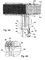
- a first pair of spears are carried by the first mounting block for reciprocal vertical movement only, the first pair including a foliage separation spear 360 and a foliage deflector spear formed of a long bar 362 and a spear point 363.
- the foliage separation spear is generally L-shaped in cross section, except that its top point is curved towards the spear point as can be seen from FIG. 4B , and it additionally has a tapered leading edge 360.1 as can best be seen from FIGS. 7 and 8 .
- a pair of right and left seedling pivotal extraction spears are indicated generally at 364 and 366, respectively.
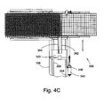
- FIGS. 4A , 4C , and 5A show the spears moving up through the seedlings carried by a tray.
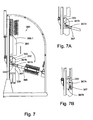
- FIGS. 6A and 7 , FIG. 6A show the initial pivotal movement of the extraction spears away from the tray of seedlings, the separation and deflector spears still being in their fully raised position.
- FIG. 7 shows the extractions spears and the separation and deflector spears in their lowered position.
- a stop arm 367 is secured to the pivot shaft 334 and carries adjustable stops 367A and 367B which limit the rotational movement of the extraction spears, the stops contacting an abutment block 333 mounted on left plate 332.
- the seedling extraction spears are designed to fit between the foliage engaging spears as can best be seen from FIGS. 4B , 5B and 5C .
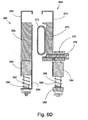
- the left foliage extraction spear 366 includes a generally rectangular member 368 as shown in FIG. 6D .
- the lower end is secured to the mounting block 358 carried by the pivot shaft 360.
- the right hand foliage extraction spear has a C-shaped elongated member 370 which carries a bladder 372 shown in its normal position in FIG. 6D .
- the pump being connected to the high pressure air compressor via suitable lines and valves.
- the cylinder 314 will now be operated to move the carriage 302 upwardly which will cause corresponding movement of the two pairs of spears.
- the leading spear point 363 of foliage deflector spear will slide up along the right hand edge of the row of seedlings which are to be engaged, and force up the stems and foliage which may be leaning to the right so they may be engaged by the seedling extracting spears.
- the left foliage separation spear which extends further away to the tray which carries the seedlings, will act to untangle the foliage of adjacent rows of seedlings to facilitate engagement.
- the seedling extraction spears will now be rotated away from the seedling trays to the position shown generally in FIG. 6A , where the cylinder 314 will now be operated to lower the carriage and both pairs of spears, the pivot shaft rotating cylinders continuing to operate to move the seedling engaging spears to their fully lowered position shown in FIG. 7 .
- the carriage 302, cylinder 314, shaft 334, and cylinders 338, 340 can be considered means for moving the foliage extraction spears 364, 366 between extended and retracted positions.
- the spears 364, 366 are moved from a position below the seedlings as shown in FIG. 4A to a position where the seedlings are between as shown in FIG. 5A , the spears 364, 366 then being moved away from the tray as shown in FIGS. 6A and then FIG. 7 .
- the root ball of the seedling will not extend to the top of the cells in the tray.
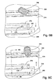
- the extraction spears do not extend into the cells of the tray, there would be a tenancy for the root balls to tip over, this being illustrated in FIG. 6B .
- the seedling loader group In order for the seedling loader group to properly engage the root balls, it is necessary to bring them into an erect position. This is accomplished by spring loaded side plates on the seedling extraction spears, which will move from a compressed position when in the FIG. 5A position where the extraction spears initially engage the stems of the seedlings, to a raised position as illustrated in FIG. 6C to cause the root-ball to assume an erect position.
- the spring loaded side plate for the right hand extraction spear 364 is indicated at 374.
- the member 370 has an elongated support 376 which is suitably secured thereto by fasteners 378. Downwardly extending dowels or rods 380 are carried by the support 376, and a bar 382 is carried at the lower ends of the dowels. Mounted for sliding movement is an apertured side plate support 384 to which the right side plate 374 is secured. Springs 386 normally bias the support 384 and plate in an upwardly direction to raise the root balls RB to the position shown in FIG. 6C .
- the left-hand seedling extraction spear 366 is also provided with a side plate 388 mounted on a side plate support 390.
- the support 390 is mounted on dowels 392 carried by an L-shaped mounting plate 394, and springs extend between a portion of the mounting plate and the side plate support to normally force the side plate to a raised position.
- the subassembly which eliminates gaps between seedlings is best illustrated in FIG. 9 .
- the gap eliminating subassembly includes a plant transfer carriage or seedling loader group indicated generally at 500, which group carries root ball loaders in the form of right and left opposed sheet metal structures 502, 504.
- the seedling loader group will engage the root balls of the seedlings and move them towards and over a pair of gap-up belts 506, 508 which run continuously during the operation of the apparatus of this invention.
- the cut-off gate will be operated in a suitable manner to release one seedling at a time, which seedling will be picked up by a discharge mechanism 700, which will be described below.
- the vertical subframe 56 which supports the seedling loader group and the gap-up belts includes a lower weldment having a pair of spaced apart vertically extending plates 512 and an upper weldment also having a pair of spaced apart vertically extending plates 514, which plates 512 and 514 may be adjustably secured to each other.
- the vertical subframe further includes upper right and left spaced apart plates 516, 518, respectively.
- each of the plates 516 and 518 are made of three pieces, which are bolted together, however, it could be made of a single piece.
- front and rear transverse plates 520, 522 Extending between upper portions 516 and 518 are front and rear transverse plates 520, 522. Each of the plates receive right and left slidable rods 526, 528. Suitably secured to the rods are a front triangular support 530 and a rear support/manifold 532.
- the mounting plate 534 for the root ball loaders 502 and 504 is interconnected to the front and rear plates 530, 532 for movement therewith.
- the arms are biased towards each other by front and rear springs 542.
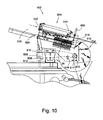
- the root ball loaders 502, 504 are moved between a forward position, shown in FIG. 9 and a rear position shown in FIGS. 9a and 10 by an air cylinder assembly 544 including cylinder 545 and rod 546.
- the anchor end of cylinder 545 is secured to the rear transverse plate 522, the front end of the cylinder 545 is supported by front transverse plate 520, the front transverse plate being apertured so that the rod 546 of the cylinder may pass through.
- the front end of the rod is secured to the front support 530. It should be apparent that as the cylinder assembly is extended, the root ball loaders 502, 504 will be moved in a forward direction, and as the cylinder is retracted the root ball loaders will be moved in a rearward direction towards the discharge mechanism 700.
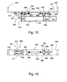
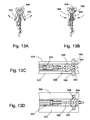
- the sheet metal root ball loaders are caused to open by a cam 548 ( FIG. 13 ).
- a rod 550 of cylinder assembly 552 carries the cam, the anchor end of cylinder 554 being secured in a suitable manner to the mounting plate 534 via nut and bolt assembly 556.
- a rod extension 558 is carried by the cam 548 and passes through a suitable bushing 560 in the front pivot plate 536.
- the cylinder assembly 552 is a double acting air cylinder and is suitably connected to ports in the rear support/manifold 532 by air lines, not shown. The manifold is in turn connected to separate air lines for controlling the extension and retraction of the cylinder.
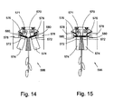
- a tip-up gate assembly 566 is provided in the seedling loader group, the tip-up gate assembly being best shown in FIGS. 9 , 12 , and 14-15 .
- the gate assembly 566 includes front and rear mounting bars 568, 570 ( FIG. 12 ). Pivotally secured to the mounting bars by pivot pins 571 are gate mounting plates 572, each of which carries a gate 574.
- the pair of gates 574 are normally spring biased to their open position shown in FIG. 14 by tension springs 576.
- tension springs 576 are normally spring biased to their open position shown in FIG. 14.
- the gates will be moved to their closed position when cam or ramp 578 is engaged by cam follower 580, causing the gates to bear against the rear root ball, moving it to an upright position before it is grasped by the seedling loader group.
- the cam followers 580 will move from the FIG. 15 position to the open position shown in FIG. 14 .
- the sheet metal structures 502, 504 will be opened. At this point the root balls will drop onto the gap-up belts 506 and 508.
- FIG. 9a shows a plurality of root balls delivered to a gap-up mechanism.
- the gap between the root balls will quickly be closed as can be seen from an inspection of FIG. 10 , the closure being achieved as the root balls are forced against each other, the rearmost root ball being held by cut-off gate 510.
- gap-up belts 506, 508 are supported by longitudinally extending high density polypropylene strips 600 carried by longitudinally extending bars 602 which are in turn carried by supports 604.
- the supports 604 are secured to right and left plates 516, 518.
- the gap-up belts are driven continuously during the operation of the machine by a DC motor 606 suitably mounted on the upper plates 516, 518.
- a cogged drive sheave 608 is mounted on the output shaft of the motor.
- a cogged belt 610 passes over the drive sheave 608 and driven cogged sheaves 612 and 614, sheave 614 being secured to cross shaft 615.
- An idler sheave 616 maintains tension in the belt.
- the sheave 612 is mounted on a cross shaft 618 suitably journalled in right and left upper plates 516 and 518, the cross shaft in turn carrying right and left drive sheaves 620 and 622 over which right and left drive belts 624, 626 are passed, these belts in turn driving the right and left gap-up belts 506 and 508.
- the longitudinally supporting bars 602 also support the front and rear sheaves over which the gap up belts pass.
- front and rear offset bar extensions 628 are provided, each of which extensions is of a L-shape.
- a side of the L-shaped bracket 628 is bolted as at 630 to an end portion of the bar 602, as indicated in FIG. 11 .
- a rotatable shaft 632 passes though a portion of the L-shaped extension beyond the bar 602.
- Mounted on the end of the shaft are driven and drive sheaves 634, 638, the driven sheave being driven from drive sheave 620 or 622 via a belt 624 or 626, and the drive sheaves 636 in turn driving the gap-up belts 506 and 508.
- the cut-off gate 510 has the function of stopping the lead root ball so that next trailing root ball will press against the leading root ball, thus eliminating any gaps.
- the cut-off gate will be operated to release root balls at precise intervals to insure that proper spacing may be achieved.
- the single cut-off gate on the feeder head is operated by a pair of double acting air cylinders 680 which are supported for adjustable longitudinal fore and aft movement by a carriage 682 supported for adjustable movement on a pair of longitudinally extending rods 684 which are in turn supported by plates 686.
- the plates are in turn supported on the right and left upper plates 516, 518 in any suitable manner.
- a screw mechanism including a screw 688 and a knurled wheel 690 may be used to adjust the position of the gate to accommodate root balls of differing diameters.
- differing nurseries use plant trays having differing sized cells.
- each of the root ball pinchers includes a L-shaped bracket 706 secured to a bar 708 secured to an upper end of the side plate 516 or 518.
- the cylinder 710 of a double acting air cylinder assembly is secured to the L-shaped bracket, the rod 712 passing through, the root ball pinchers 702 being secured to the rod.
- a guide rod 714 also extends from the L-shaped bracket.
- Each root ball pincher includes a flared pressure plate 716 mounted on a block 718.
- the block 718 is secured to the rod 712, and is provided with a suitable slot 720 or aperture for sliding receipt of the guide rod 714.
- Simultaneous actuation of the cylinder assemblies 710, 712 will cause opposed root ball pinchers in the form of the pressure plates 716 to either move towards each other to pinch and hold the root balls from further movement, or to release the root balls so that they can be advanced.
- the pressure plates are flared to a more open position towards the spears, so that as the root balls are advanced towards the discharge disk assembly they will not catch upon the ends of the plates, but will easily slide in.
- the discharge disk assembly 704 includes right and left flexible high density polyethylene plastic disks 724, 726 which are suitably mounted for continuous rotation with driven shaft 615 ( FIG. 18A ), the shaft being driven by cogged belt 610 which passes over cogged sheave 614. (although the disks may be made of polypropylene, other suitable materials may be employed.)
- the shaft 615 is journalled in right and left bearings 728, 730 carried by right and left side plates 516, 518, respectively.
- a mounting block 732 is secured to shaft 615 for rotation therewith, the block being located midway between the side plates.
- the disks 724 and 726 are suitably secured to the mounting block by conventional fasteners.
- Means are provided to shape the disks as they are rotated in a clockwise direction as viewed in FIG. 9 .
- the disks are flexible and can move from side to side, and when forced towards each other they have the ability to grasp a root ball when the gate 510 is moved up to release a single seedling, the others being held by the root ball pinchers.
- the disks In order for the disks to be able to engage and transport seedlings, they are forced to together by three opposed pairs of rollers 750, 752, and 754, respectively. To this end each pair of rollers is carried by suitable leaf springs 756 which are in turn carried by suitable mounts 758 secured to the side plates 516, 518.
- a drop tube assembly including a funnel like structure 770 is suitably mounted below the disks 724, 726 for the receipt of seedlings, the drop tube assembly terminating in a drop tube 780.
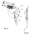
- a disk release member 772 extends between the disks 724, 726 as can be seen from FIGS. 18A , 19 and 20 . As the disks are rotated in a clockwise direction as viewed in FIG.
- the rollers and leaf springs will force the disks together to cause them to grasp and raise a seedling away from the gap-up belts at the area of the gate, and to transport them to a drop zone where they are caused to drop by gravity as the disks are forced apart by the disk release member 772.
- a flow of air directed by air jet 774 will facilitate the discharge.
- a second flow of air from air knife 776, which is connected to manifold 778, will prevent leaves from adhering to the rear side of the funnel 770.
- the row unit planter frame subassembly 800 is adapted to be secured to the tool bar 32 shown in FIG. 1 .
- the subassembly includes a mounting weldment 802 which may be secured to the tool bar in any conventional manner.
- Upper and lower parallel links 804 and 806 are pivotally secured to the weldment by front upper and lower bushing assemblies 808 and 810.
- the rear ends of the upper and lower links are pivotally secured to a further weldment indicated generally at 812 by upper and lower rear bushing assemblies 813 and 814.
- the weldment 812 includes right and left vertically extending side bars 815 ( FIG.
- a cylinder 807 is mounted between the weldment 802 and the weldment 812 for the purpose of applying either a raising or a lowering force to the weldment 812.
- a soil conditioning unit indicated generally at 821 is pivotally secured to the lower end of weldment 812.
- the soil conditioner unit includes a pair of arms 822 which are carried by the lower ends of side bars 815, 816 by pivots 824.
- the forward ends of the arms carry a soil conditioner, such as for example a soil conditioning wheel 826.
- the height of the soil conditioning unit can be adjusted by an screw mechanism indicated generally at 828, the details of which should be apparent from an inspection of the drawings.
- a furrow opener 830 is secured to the weldment 812 by a vertical bar 832 which is in turn secured to a transverse plate 834 and a bracing plate 836, these parts being welded together.
- the furrow opener is of a generally V shaped construction, the apex of the V being to the forward side, and the spaced apart sides of the V being flared to the upper side.
- the furrow opener may be provided with various ports 838 for the introduction of water into the soil during planting.
- a skid plate 840 for flattening the soil immediately before the seedlings are introduced into the soil.
- the planter subframe may be split into two parts, a forward subframe indicated generally at 1100 and a rear subframe indicated generally at 1102.
- a forward subframe indicated generally at 1100 and a rear subframe indicated generally at 1102.
- upper and lower right and left fore and aft extending frame members 818 and 820 are connected at their forward ends to the right and left side bars 815 and 816, respectively.
- each of the lower frame members 820 are provided with upwardly extending C-shaped cut-outs 1108.
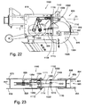
- the rear subframe 1102 consists essentially of right and left mounting subassemblies including right and left side plates 1109 and 1110, respectively and right and left vertically extending mounting bars 1111 and 1112, which bars are carried at their lower ends by a transverse pivot shaft 1113 ( FIG. 22 ) which is received in the upwardly extending C-shaped cut-outs 1108.
- Each of the bars 1111 and 1112 carries a cylindrical rod 1114 which is received in C-shaped cutout 1116 in the upper frame
- a C-shaped bracket 846 is secured to the trailing ends of the side plates 1109, 1110, which bracket supports a press wheel supporting weldment which is secured thereto by suitable bolts 849.
- the weldment includes a vertical plate 850, rearwardly extending plate 851, and reinforcing gusset 852.
- Welded to the lower side edges of the plate 851 and to the sides of vertical plate 850 are right and left longitudinally extending press wheel mounting brackets 854 and 855, respectively which are suitably angled to the vertical.
- Right and left press wheels 856 and 857 are carried by the brackets 854, 855, respectively by suitable shaft assemblies 858, the details of which are not illustrated.
- a press wheel scraper assembly which includes right and left mounting tubes 860, 861 suitably secured to the inner sides of the brackets, the tubes carrying at the rear ends a transverse tube 862 provided with suitable press wheel scrapers 863.
- the planter subframe assembly further includes right and left knife coulters, only the left coulter 868 being illustrated. These coulters are secured to the horizontal rearwardly extending bars, one of which is shown at 820.
- gusseted L-shaped brackets 871 are provided, each having elongated horizontal slots through which suitable bolts pass, the slots permitting adjustment of the brackets in a fore and aft direction.
- a horizontal slotted bar 872 Disposed below each of the brackets is a horizontal slotted bar 872 provided with an elongated slot (not shown) through which are passed suitable bolts for adjustably securing the bars in place.
- the horizontal bars each carry mounting brackets 874 through which pass cylindrical shafts 876 which carry at their lower ends the knife coulters. While knife coulters are illustrated it should be apparent that other forms of coulters may be employed, for example disk coulters.
- the plant feeder subassembly 1300 of this invention is mounted immediately below the drop tube 780 as can best be seen from FIGS. 1B and 24 .
- the planter feeder includes as its principal components right and left forward transfer disks 1302 and 1303, respectively, and right and left rear planting disks 1304 and 1305, respectively.
- Each of these disks is of a construction similar to the disks 724, 726, however the forward transfer disks are 1/2 the diameter of the rear planting disks. To this end both sets of disks are driven in such a manner that they have the same peripheral speed.
- the drive for the disks includes a motor 1308 mounted on the right and left side plates 1109 and 1110, which motor drives a cross shaft 1310 carried by suitable bushings on the side plates, the motor driving the shaft through a suitable chain (not shown) and sprocket 1309.
- a pair of drive sprockets 1312 and 1322 are mounted on the shaft for rotation therewith.
- Sprocket 1312 has a suitable chain 1316 disposed over it, which chain is also disposed over another sprocket 1318 carried by a cross shaft 1320 carried by suitable bushings mounted on the right and left side plates 1109 and 1110.
- a planting pinch disk assembly including left and right rear planting disks 1304 and 1305.
- the sprocket 1322 drives a gear 1324 through a further chain 1326.
- the gear 1324 is carried by extensions of the side plates 1109 and 1110 of the rear subframe 1102 and can be moved away from the forward subframe 1100.
- a further gear 1328 This gear will in turn cause the left and right transfer disks 1302 and 1303 to be rotated.
- a chain 1330 drives a sprocket 1332 on the shaft which carries the disks 1302 and 1303, causing the disks to be rotated.
- the chain also passes over idler sprockets 1334 and 1336 carried by a pivoted beam 1338.
- the seedling disks can be moved between forward or rear positions through various intermediate positions, not shown.
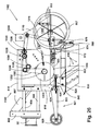
- the transfer disks should be in the position shown in FIG. 24A , but when the seedlings have a greater height, the disks should be in a forward position as shown in FIG. 26 .
- the transfer disks are supported on a slidable subassembly 1340 which moves on an upper and two lower slide shafts 1342.
- a screw servomotor 1344 which may be controlled by the operator.
- Mounted on the subassembly 1340 is a V-shaped seedling receiver 1346 which extends between the transfer disks 1302, 1303.
- a double door 1347 is mounted to the rear of the seedling receiver and above the transfer disks, the door preventing the root ball, stem, and foliage from tipping to the rear.
- a kicker 1348 will be extended by cylinder assembly 1350 to move the seedlings to the rear where the root ball is caught by the transfer disks 1302, 1303 which have the same peripheral speed as the planting disks 1304, 1305.
- a double acting cylinder assembly 1351 will cause the double doors 1347 to be opened. After the root ball had been kicked out, and the kicker retracted, the double doors will be shut again by the cylinder assembly 1351.
- Extending rearwardly from the slidable subassembly 1340 are a pair of sheet metal sidewalls, one of which is illustrated at 1352 in FIG. 24A . These sidewalls each carry an air knife 1354 for the purpose of extending the stems and leaves at the time of transfer from the transfer disks to the planting disks.
- the tray indexing mechanism will properly position a tray so that the subassembly 300 for picking up an entire row of seedlings from a tray can transfer those seedlings to the subassembly 500 for eliminating gaps between seedlings.
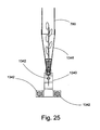
- the discharge mechanism 700 which includes a feeder pinch disk assembly 724, 726, will pick up and drop individual seedlings to a drop tube 780 for receipt by a planter assembly. With reference now to FIG. 25 and FIGS 31A-31D , the seedling will be dropped into the V-shaped seedling receiver 1346. When desired, as shown in FIG.
- the kicker 1348 will be extended by cylinder assembly 1350 to move the seedling to the rear where the root ball is caught by the transfer disks 1302, 1303 which have the same peripheral speed as the planting disks 1304, 1305.
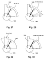
- the opposed air knifes acting in the foliage stick correction area shown in FIGS. 30 and 31C will cause the foliage and stem to be extended so that the seedling can be effectively engaged by the planting disks and then moved in a counter-clockwise direction.
- the press wheels will cause it to be held by the ground. In operation, about 2 seedlings will be serially planted every second by each row unit of this transplanter.
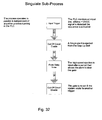
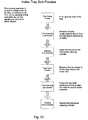
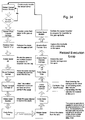
- FIGS. 32-36 show various flow charts relevant to the operation of this apparatus.
- the movement of the spears is controlled in part by the reload execution loop set forth in FIG. 32 .
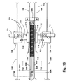
- This control sequence will be triggered from a laser sensor receiver 1000 best shown in FIG. 16 .
- This optical sensor monitor will be monitored as shown in FIG. 32 .
- the monitor receives a continuous signal from the laser emitter 1002, indicating the absence of a root ball on the gap-up belts
- the plant transfer carriage or seedling loader group will be moved from the extended position shown in FIG. 9 to the retracted position shown in FIG. 9a .
- the seedlings will be released, and the spears will be operated as set forth in FIG. 32 .
- the laser emitter and laser sensor are mounted on brackets 1004, 1006, respectively, which are mounted in turn on the right and left plates 516, 518.
- the flow chart of FIG. 33 sets forth the process for indexing the trays. This process will not be initiated until it is called to operate from the reload execution loop set forth in FIG. 32 .
- the flow chart of FIG. 34 sets forth the controls for the gate 510 which releases a single seedling at a time from the gap-up mechanism.
- the input trigger is responsive to an input signal received from the wheel encoder processor illustrated in FIG. 36 , the gate 510 being operated in the same frequency as the gate 942.
- the operation of the cut-off gate 680 is responsive to a PLC (or the equivalent) trigger input received from the wheel encoder processor, and after a finite delay, the gate cylinder 944 will be operated.
- the wheel encoder processor is responsive to a signal generated from a wheel encoder carried by a sensing wheel (not illustrated) which generates a distance signal as a function of the distance travelled by the transplanter.
Landscapes
- Life Sciences & Earth Sciences (AREA)
- Soil Sciences (AREA)
- Environmental Sciences (AREA)
- Transplanting Machines (AREA)
Claims (13)
- Procédé de transplantation pour transplanter des plants ayant été mis à croître dans des plateaux ayant plusieurs rangées côte à côte de cellules de plant, lequel procédé plante les plants écartés de manière uniforme même si toutes les cellules n'ont pas de plant, le procédé étant caractérisé par les étapes suivantes consistant à :- prélever une rangée entière de plants à partir d'un plateau par mise en prise des tiges des plants, laquelle rangée dans le plateau peut avoir des espaces entre les plants ;- transférer les plants vers un mécanisme qui élimine les espaces entre les plants ; et- ensuite décharger les plants un à la fois avec un écartement voulu entre les plants.
- Appareil pour transplanter des plants ayant été mis à croître dans des plateaux (116) ayant plusieurs rangées côte à côte de cellules de plant (116c), lequel appareil plante les plants écartés de manière uniforme même si toutes les cellules n'ont pas de plant, l'appareil étant caractérisé par- des moyens (300) pour prélever une rangée entière de plants à partir d'un plateau par mise en prise des tiges des plants ;- des moyens (500) pour éliminer les espaces entre des plants ;- des moyens (700) pour décharger les plants un à la fois avec un écartement voulu entre les plants ; et- un ensemble de plantoir (300, 1300) pour planter les plants écartés de manière uniforme dans le sol.
- Appareil selon la revendication 2 caractérisé en outre en ce qu'il comporte la fourniture d'un mécanisme d'indexation de plateau (100) qui avance un plateau (116) approximativement d'une largeur de cellule à la fois, et ensuite positionne en outre le plateau par mise en prise d'une cellule (116c) avec un piston plongeur (220) de centrage de plateau en forme de V de positionnement de plateau, qui est poussé dans une cellule vide d'une rangée adjacente à la rangée contenant les plants qui ont été prélevés pour être plantés pour assurer que le plateau est dans la position voulue.
- Appareil selon les revendications 2 ou 3, dans lequel les moyens (300) pour prélever une rangée entière de plants à partir d'un plateau comprennent une paire d'aiguilles d'extraction de plants (364, 366) qui viennent en prise avec les tiges des plants et tirent celles-ci et les pains racinaires associés (RB) à partir d'un plateau.
- Appareil selon la revendication 4, dans lequel au moins une des aiguilles d'extraction contient une vessie (372) qui peut être gonflée pour venir en contact avec les tiges de la rangée de plants qui sont prélevés.
- Appareil selon les revendications 4 ou 5 comprenant des moyens de déplacement (302, 314, 334, 338, 340) pour déplacer la paire d'aiguilles d'extraction depuis une position rétractée vers une position étendue le long d'une rangée de plants de sorte que la paire d'aiguilles d'extraction est située sur des côtés opposés des tiges des plants dans la rangée à extraire, et ensuite déplacer les aiguilles d'extraction dans une direction s'éloignant de la surface du plateau pour extraire les plants.
- Appareil selon la revendication 6 comprenant de plus une paire supplémentaire d'aiguilles comprenant une aiguille de séparation de feuillage (360) et une aiguille de déviation de feuillage (362), laquelle autre paire d'aiguilles entoure la paire d'aiguilles d'extraction (364, 366), les moyens de déplacement amenant le second ensemble d'aiguilles à se déplacer avec la paire d'aiguilles d'extraction depuis une position rétractée jusqu'à une position étendue et ensuite restant initialement en place lorsque la paire d'aiguilles d'extraction initialement se déplace dans une direction s'éloignant de la surface du plateau, l'aiguille de séparation de feuillage retenant la rangée adjacente des plants en place lorsque les aiguilles d'extraction extraient une rangée de plants l'aiguille de séparation de feuillage démêlant le feuillage lorsqu'elle se déplace depuis la position rétractée vers la position étendue, et l'aiguille de déviation de feuillage poussant le feuillage et les tiges vers le haut.
- Appareil selon les revendications 6 ou 7, dans lequel chacune des aiguilles d'extraction (364, 366) est munie de plaques latérales chargées par ressort (374, 388), qui vont monter pour amener les pains racinaires (RB) à prendre une position érigée lorsque les aiguilles d'extraction sont amenées à s'éloigner de la surface du plateau.
- Appareil selon l'une quelconque des revendications 2 à 8 dans lequel les moyens pour éliminer des espaces entre les plants sont une paire de courroies s'étendant en continu écartées (506, 508) qui reçoivent une rangée de plants, les pains racinaires des plants étant supportés sur les courroies, et les tiges et le feuillage s'étendant vers le bas entre les courroies, et une barrière (510) qui limite le déplacement des plants reçus sur les courroies, provoquant des espaces à éliminer entre les plants, les courroies circulant à une vitesse plus grande que la vitesse de décharge de sorte que les espaces entre les pains racinaires peuvent être éliminés.
- Appareil selon la revendication 9 comprenant de plus au moins un élément parmi :- un chargeur de pains racinaires (502, 504) qui vient en prise avec les pains racinaires transportés par les aiguilles d'extraction de plants et met les pains racinaires sur la paire de courroies ;- des tenailles de pains racinaires (702) qui agissent en concert avec la barrière (510) pour maintenir les pains racinaires qui ont avancé jusqu'à un emplacement proche de la barrière alors que le pain racinaire de tête est déchargé lorsque la barrière est ouverte.
- Appareil selon les revendications 9 ou 10, dans lequel les moyens pour décharger les plants comprennent un ensemble de disques de décharge (704) ayant des disques rotatifs écartés souples (724, 726) qui viennent en contact avec la tige et le feuillage de chaque plant libéré par la barrière (510) et ensuite mettent en rotation le plant sur environ 180° de sorte que le pain racinaire est vers le bas lorsqu'il est libéré vers un tube de chute (780).
- Appareil selon l'une quelconque des revendications précédentes 2 à 11, dans lequel les moyens pour décharger les plants un à la fois vers le sol avec un écartement voulu entre les plants comprennent un codeur de roue et une barrière (510) qui est sensible à un signal produit par le codeur de roue qui identifie l'écartement au sol correct.
- Appareil selon l'une quelconque des revendications précédentes, dans lequel les moyens pour décharger les plants un à la fois sur le sol avec un écartement voulu entre les plants comprennent au moins un élément parmi :- un ensemble de disques de pincement d'alimentation (704), un ensemble de tube de chute (770, 780), un ensemble d'alimentation de plantoir (1300) qui reçoit des plants en provenance de l'ensemble de tube de chute, un ensemble de disques de pincement de plantoir (1304, 1305) qui reçoit des plants provenant de l'ensemble d'alimentation de plantoir et les positionne dans le sol avec l'écartement voulu ,- une paire de disques de transfert vers l'avant (1302, 1303) qui reçoit les plants provenant du tube de chute et les écarte de l'ensemble de disques de pincement de plantoir (1304, 1305) ;- des moyens de couteau pneumatique (1354) pour étendre la tige et le feuillage d'un plant alors qu'il est dans la paire de disques de transfert vers l'avant pour être mis en prise correcte par la paire arrière de disques planteurs.
Applications Claiming Priority (3)
| Application Number | Priority Date | Filing Date | Title |
|---|---|---|---|
| US96364507P | 2007-08-04 | 2007-08-04 | |
| US99832907P | 2007-10-10 | 2007-10-10 | |
| US6757508P | 2008-02-29 | 2008-02-29 |
Publications (3)
| Publication Number | Publication Date |
|---|---|
| EP2022323A2 EP2022323A2 (fr) | 2009-02-11 |
| EP2022323A3 EP2022323A3 (fr) | 2009-04-15 |
| EP2022323B1 true EP2022323B1 (fr) | 2012-06-13 |
Family
ID=39926416
Family Applications (1)
| Application Number | Title | Priority Date | Filing Date |
|---|---|---|---|
| EP08161764A Not-in-force EP2022323B1 (fr) | 2007-08-04 | 2008-08-04 | Transplantoir |
Country Status (3)
| Country | Link |
|---|---|
| US (1) | US7954439B2 (fr) |
| EP (1) | EP2022323B1 (fr) |
| CA (1) | CA2638147C (fr) |
Cited By (1)
| Publication number | Priority date | Publication date | Assignee | Title |
|---|---|---|---|---|
| AU2007100035B9 (en) * | 2006-01-17 | 2013-10-31 | Transplant Systems Pty Limited | Transplanting apparatus |
Families Citing this family (26)
| Publication number | Priority date | Publication date | Assignee | Title |
|---|---|---|---|---|
| US8573142B2 (en) * | 2008-07-31 | 2013-11-05 | Faulring Mechanical Devices, Inc. | Foliage separator for a transplanter |
| US7905186B2 (en) * | 2008-07-31 | 2011-03-15 | The Morning Star Company | Transplanting apparatus |
| EP2223585B1 (fr) | 2009-02-04 | 2012-07-11 | Faulring Mechanical Devices, Inc | Transplanteur |
| WO2012121653A1 (fr) * | 2011-03-10 | 2012-09-13 | Björkemar Construction & Consulting Bcc Ab | Procédé de manipulation des plantes dans une repiqueuse, repiqueuse et unité de repiquage |
| US9635804B2 (en) | 2012-06-18 | 2017-05-02 | Gary W. Clem, Inc. | Drop tube system for planting field seeds in rows with different varieties of seeds |
| BR112016001881B1 (pt) * | 2013-08-02 | 2020-01-28 | Basf Se | aparelho para plantio e tratamento de mudas de uma planta agrícola e uso de aparelho |
| WO2016195604A1 (fr) | 2015-06-03 | 2016-12-08 | Kasetsart University | Appareil pour le transfert de semis ou de produits de propagation de plante, et son procédé |
| CN107046891A (zh) * | 2016-12-13 | 2017-08-18 | 重庆市神女药业股份有限公司 | 中药材幼苗送苗装置 |
| WO2018157215A1 (fr) * | 2017-03-03 | 2018-09-07 | Williames Pty Ltd | Améliorations apportées à des repiqueuses sélectives automatiques |
| CN107079641A (zh) * | 2017-05-17 | 2017-08-22 | 山东省农业机械科学研究院 | 水稻钵体苗旱地移栽联合作业机 |
| JP6717275B2 (ja) * | 2017-09-19 | 2020-07-01 | 井関農機株式会社 | 作業車両 |
| CN108450100B (zh) * | 2018-03-19 | 2023-06-23 | 长江大学 | 一种钵苗移栽机的移栽装置 |
| SG11202011160VA (en) * | 2018-05-28 | 2020-12-30 | Ima Co Ltd | Seedling transplanter |
| US11350560B1 (en) | 2018-07-11 | 2022-06-07 | Hoy Ayers Buell | Mechanical transplanter |
| CN108781668A (zh) * | 2018-09-03 | 2018-11-13 | 石河子大学 | 一种基于蜗牛凸轮机构的整排顶苗装置 |
| CN110149862B (zh) * | 2019-07-05 | 2022-01-04 | 桂林理工大学 | 一种移栽机取苗装置及自动移栽机 |
| CN110972617B (zh) * | 2019-12-24 | 2022-08-09 | 湖南农业大学 | 一种种沟沟深自动调节装置 |
| CN111572838A (zh) * | 2020-05-19 | 2020-08-25 | 宋志国 | 一种蔬菜苗装箱装置 |
| CA3134298C (fr) * | 2021-03-03 | 2026-03-17 | Equipements Vegtech | Appareil et methode d'alimentation d'une transplanteuse |
| CN112930809A (zh) * | 2021-04-23 | 2021-06-11 | 石河子大学 | 一种自动整排取苗装置 |
| CN113303061A (zh) * | 2021-07-14 | 2021-08-27 | 江西省农业科学院农业工程研究所 | 一种蔬菜移栽机自动喂苗装置 |
| CN113767738B (zh) * | 2021-09-30 | 2022-10-11 | 保定凯若特农业科技有限公司 | 种苗全自动化移栽机 |
| CN115053676B (zh) * | 2022-07-27 | 2024-03-26 | 浙江大学 | 一种环形轨道式剔苗补苗移栽机 |
| CN116584275B (zh) * | 2023-04-13 | 2024-01-05 | 西藏藏建物生绿化有限责任公司 | 一种林业苗木培育系统及培育方法 |
| CN119698999B (zh) * | 2023-09-26 | 2025-10-21 | 广州极飞科技股份有限公司 | 无人机抛秧控制方法及装置、抛秧系统和可读存储介质 |
| CN118770916B (zh) * | 2024-09-10 | 2024-12-03 | 吉林农业科技学院 | 一种钵体育苗移载用运输储存装置 |
Family Cites Families (38)
| Publication number | Priority date | Publication date | Assignee | Title |
|---|---|---|---|---|
| US2348787A (en) | 1943-04-09 | 1944-05-16 | Henry P Cordes | Planting mechanism |
| US2475078A (en) | 1945-08-07 | 1949-07-05 | Willie K Cherry | Transplanter drill set |
| US2784997A (en) | 1955-04-05 | 1957-03-12 | Baxter Laboratories Inc | Inflatable gripping mechanism |
| DE1143359B (de) | 1956-03-07 | 1963-02-07 | Dr Viktor Koran | Einrichtung zum Fuellen und Bepflanzen von Pikiertoepfen |
| US3524419A (en) | 1968-06-27 | 1970-08-18 | Hawaiian Sugar Planters Assoc | Method and apparatus for transplanting plants |
| US3712252A (en) | 1970-11-06 | 1973-01-23 | Research Corp | Seedling growing and handling device |
| US3826382A (en) | 1973-01-04 | 1974-07-30 | A Zappia | Case packer |
| US4455950A (en) | 1977-08-22 | 1984-06-26 | General Mills, Inc. | Transplanting apparatus utilizing a disc mechanism for transferring plants from a supply tape to the furrow |
| US4616578A (en) | 1983-05-12 | 1986-10-14 | Talbott Gene B | Automatic method and apparatus for transplanting crops |
| US4644880A (en) | 1985-02-22 | 1987-02-24 | Growers Transplanting, Inc. | Method and apparatus for transplanting corps |
| DE3751583D1 (de) | 1986-02-06 | 1995-12-14 | Williames Hi Tech Int | Pflanzgerät für setzlinge. |
| US4750439A (en) | 1986-08-27 | 1988-06-14 | Bud Antle, Inc. | Planting finger assembly |
| US4869637A (en) | 1986-08-27 | 1989-09-26 | Bud Antle, Inc. | Plant transfer mechanism |
| US4835946A (en) | 1987-01-28 | 1989-06-06 | Hartness International | Article transport apparatus |
| US4709536A (en) | 1987-01-28 | 1987-12-01 | Hartness International, Inc. | Article transport apparatus |
| EP0286624A1 (fr) | 1987-04-10 | 1988-10-12 | Karl F. Rath Ges.m.b.H. Kärntner Forstbaumschulen | Dispositif de plantation de plantes en pots et de placement des pots sur un lit |
| FI84870C (fi) | 1987-11-02 | 1992-02-10 | Laennen Tehtaat Oy | Foerfarande och anordning foer plantering av klumpplantor. |
| ATE125105T1 (de) | 1988-12-29 | 1995-08-15 | Nagano Prefecture | Pflanzmaschine. |
| WO1990010377A1 (fr) | 1989-03-07 | 1990-09-20 | Williames Hi-Tech International Pty. Ltd. | Montage de transfert de semences |
| AT392564B (de) | 1989-03-31 | 1991-04-25 | Visser S Gravendeel Holding | Einrichtung zum versetzen von magazinierten jungpflanzen |
| SE500403C2 (sv) | 1989-10-11 | 1994-06-20 | Stora Kopparbergs Bergslags Ab | Sätt och anordning för att ordna och packa plantor |
| US5573558A (en) | 1991-03-11 | 1996-11-12 | Huang; Barney K. | Automatic transplanting system |
| US5676072A (en) | 1992-08-10 | 1997-10-14 | Williames Hi-Tech International Pty Ltd. | Apparatus for automatically planting seedlings taken from a hard seedling tray |
| US5431116A (en) | 1993-10-26 | 1995-07-11 | New Century Technology Corporation | Pneumatic transplanter |
| US5860372A (en) | 1995-02-21 | 1999-01-19 | Bouldin & Lawson, Inc. | Seedling transplanter with planting fingers |
| US5557881A (en) | 1995-02-21 | 1996-09-24 | Bouldin; Floyd | Seedling transplanter |
| US5577453A (en) | 1995-06-08 | 1996-11-26 | Northwest Transplants | Adjustable compacting skid for mechanical transplanter |
| US5765491A (en) | 1996-09-05 | 1998-06-16 | Precision Measurements Corporation | Seedling transfer apparatus and method |
| US5911631A (en) | 1996-09-23 | 1999-06-15 | Bouldin & Lawson, Inc. | Seedling transplanter with easily detachable gripper |
| US5823126A (en) | 1996-12-13 | 1998-10-20 | Mechanical Transplanter Company | Mechanical seedling transplanter |
| US6591766B2 (en) | 1996-12-31 | 2003-07-15 | Williames Hi-Tech International Pty Ltd. | Field transplanter |
| CA2276607C (fr) | 1996-12-31 | 2006-08-01 | Williames Hi-Tech International Pty. Ltd. | Repiqueuse |
| FI102937B (fi) | 1997-10-24 | 1999-03-31 | Laennen Tehtaat Oy | Menetelmä ja laite paakkutaimien istutuksen tehostamiseksi |
| US6073564A (en) | 1998-04-21 | 2000-06-13 | Lannen Tehtaat Oy | Method and device for improving the transplanting of seedlings |
| US6212821B1 (en) | 1999-05-10 | 2001-04-10 | Kieran L. Adam | Automatic plant selector |
| US6634306B1 (en) | 2002-07-30 | 2003-10-21 | Frank W. Faulring | Method and apparatus for transplanting |
| US7036440B1 (en) | 2002-09-12 | 2006-05-02 | Gil A Sena | Adjustable tray size automatic seedling planting apparatus |
| US7051475B1 (en) | 2003-09-12 | 2006-05-30 | Gil A Sena | Adjustable tray size automatic seedling planting apparatus |
-
2008
- 2008-07-31 US US12/221,081 patent/US7954439B2/en not_active Expired - Fee Related
- 2008-08-01 CA CA2638147A patent/CA2638147C/fr active Active
- 2008-08-04 EP EP08161764A patent/EP2022323B1/fr not_active Not-in-force
Cited By (1)
| Publication number | Priority date | Publication date | Assignee | Title |
|---|---|---|---|---|
| AU2007100035B9 (en) * | 2006-01-17 | 2013-10-31 | Transplant Systems Pty Limited | Transplanting apparatus |
Also Published As
| Publication number | Publication date |
|---|---|
| US7954439B2 (en) | 2011-06-07 |
| CA2638147A1 (fr) | 2009-02-04 |
| US20090031935A1 (en) | 2009-02-05 |
| CA2638147C (fr) | 2012-06-12 |
| EP2022323A2 (fr) | 2009-02-11 |
| EP2022323A3 (fr) | 2009-04-15 |
Similar Documents
| Publication | Publication Date | Title |
|---|---|---|
| CA2638147C (fr) | Transplanteuse | |
| US8122838B2 (en) | Transplanter | |
| US7905186B2 (en) | Transplanting apparatus | |
| AU753952B2 (en) | Field transplanter | |
| DE69328782T2 (de) | Automatische pflanzmaschine topfballen aus einer saatkiste nehmend | |
| WO1995004451A9 (fr) | Dispositif pour le repiquage de pousses de semis | |
| JP5000135B2 (ja) | 自動化プランター | |
| WO1995004451A1 (fr) | Dispositif pour le repiquage de pousses de semis | |
| US20190045706A1 (en) | Systems, Devices and Components for Automated Planting and Supporting Automated Planters and Methods of Using Same | |
| US5860372A (en) | Seedling transplanter with planting fingers | |
| US5121701A (en) | Transplating apparatus | |
| EP1624743B1 (fr) | Procede et dispositif pour la delivrance de plantes jeunes sur le sol dans une planteuse | |
| EP2223585B1 (fr) | Transplanteur | |
| EP0258293A1 (fr) | Machine a planter des jeunes plants. | |
| AU2008207456A1 (en) | Transplanting apparatus | |
| AU2010200555A1 (en) | Transplanting apparatus | |
| EP1472924A1 (fr) | Procédé et appareil pour transporter des plateaux à semis dans une planteuse | |
| WO2006068518A1 (fr) | Tete de transplantation de semis | |
| AU633387B2 (en) | Transplanting apparatus | |
| JP2007089540A (ja) | 根菜類の収穫機 | |
| US3979888A (en) | Machine for cutting and harvesting graminaceous plants | |
| JP3513235B2 (ja) | 接木装置における穂部運搬装置 | |
| AU7480294A (en) | A transplanter for seedlings | |
| JPH06189632A (ja) | 接ぎ木苗供給装置 | |
| JP2004254641A (ja) | 苗挿し機 |
Legal Events
| Date | Code | Title | Description |
|---|---|---|---|
| PUAI | Public reference made under article 153(3) epc to a published international application that has entered the european phase |
Free format text: ORIGINAL CODE: 0009012 |
|
| AK | Designated contracting states |
Kind code of ref document: A2 Designated state(s): AT BE BG CH CY CZ DE DK EE ES FI FR GB GR HR HU IE IS IT LI LT LU LV MC MT NL NO PL PT RO SE SI SK TR |
|
| AX | Request for extension of the european patent |
Extension state: AL BA MK RS |
|
| PUAL | Search report despatched |
Free format text: ORIGINAL CODE: 0009013 |
|
| AK | Designated contracting states |
Kind code of ref document: A3 Designated state(s): AT BE BG CH CY CZ DE DK EE ES FI FR GB GR HR HU IE IS IT LI LT LU LV MC MT NL NO PL PT RO SE SI SK TR |
|
| AX | Request for extension of the european patent |
Extension state: AL BA MK RS |
|
| 17P | Request for examination filed |
Effective date: 20091007 |
|
| AKX | Designation fees paid |
Designated state(s): AT BE BG CH CY CZ DE DK EE ES FI FR GB GR HR HU IE IS IT LI LT LU LV MC MT NL NO PL PT RO SE SI SK TR |
|
| 17Q | First examination report despatched |
Effective date: 20100930 |
|
| REG | Reference to a national code |
Ref country code: DE Ref legal event code: R079 Ref document number: 602008016281 Country of ref document: DE Free format text: PREVIOUS MAIN CLASS: A01G0009080000 Ipc: A01G0009100000 |
|
| GRAP | Despatch of communication of intention to grant a patent |
Free format text: ORIGINAL CODE: EPIDOSNIGR1 |
|
| RIC1 | Information provided on ipc code assigned before grant |
Ipc: A01G 9/08 20060101ALI20111117BHEP Ipc: A01C 11/02 20060101ALI20111117BHEP Ipc: A01G 9/10 20060101AFI20111117BHEP |
|
| GRAS | Grant fee paid |
Free format text: ORIGINAL CODE: EPIDOSNIGR3 |
|
| GRAA | (expected) grant |
Free format text: ORIGINAL CODE: 0009210 |
|
| AK | Designated contracting states |
Kind code of ref document: B1 Designated state(s): AT BE BG CH CY CZ DE DK EE ES FI FR GB GR HR HU IE IS IT LI LT LU LV MC MT NL NO PL PT RO SE SI SK TR |
|
| REG | Reference to a national code |
Ref country code: GB Ref legal event code: FG4D |
|
| REG | Reference to a national code |
Ref country code: AT Ref legal event code: REF Ref document number: 561555 Country of ref document: AT Kind code of ref document: T Effective date: 20120615 Ref country code: CH Ref legal event code: EP |
|
| REG | Reference to a national code |
Ref country code: IE Ref legal event code: FG4D |
|
| REG | Reference to a national code |
Ref country code: DE Ref legal event code: R096 Ref document number: 602008016281 Country of ref document: DE Effective date: 20120809 |
|
| REG | Reference to a national code |
Ref country code: NL Ref legal event code: VDEP Effective date: 20120613 |
|
| PG25 | Lapsed in a contracting state [announced via postgrant information from national office to epo] |
Ref country code: CY Free format text: LAPSE BECAUSE OF FAILURE TO SUBMIT A TRANSLATION OF THE DESCRIPTION OR TO PAY THE FEE WITHIN THE PRESCRIBED TIME-LIMIT Effective date: 20120613 Ref country code: SE Free format text: LAPSE BECAUSE OF FAILURE TO SUBMIT A TRANSLATION OF THE DESCRIPTION OR TO PAY THE FEE WITHIN THE PRESCRIBED TIME-LIMIT Effective date: 20120613 Ref country code: NO Free format text: LAPSE BECAUSE OF FAILURE TO SUBMIT A TRANSLATION OF THE DESCRIPTION OR TO PAY THE FEE WITHIN THE PRESCRIBED TIME-LIMIT Effective date: 20120913 Ref country code: FI Free format text: LAPSE BECAUSE OF FAILURE TO SUBMIT A TRANSLATION OF THE DESCRIPTION OR TO PAY THE FEE WITHIN THE PRESCRIBED TIME-LIMIT Effective date: 20120613 Ref country code: LT Free format text: LAPSE BECAUSE OF FAILURE TO SUBMIT A TRANSLATION OF THE DESCRIPTION OR TO PAY THE FEE WITHIN THE PRESCRIBED TIME-LIMIT Effective date: 20120613 |
|
| REG | Reference to a national code |
Ref country code: AT Ref legal event code: MK05 Ref document number: 561555 Country of ref document: AT Kind code of ref document: T Effective date: 20120613 |
|
| REG | Reference to a national code |
Ref country code: LT Ref legal event code: MG4D Effective date: 20120613 |
|
| PG25 | Lapsed in a contracting state [announced via postgrant information from national office to epo] |
Ref country code: LV Free format text: LAPSE BECAUSE OF FAILURE TO SUBMIT A TRANSLATION OF THE DESCRIPTION OR TO PAY THE FEE WITHIN THE PRESCRIBED TIME-LIMIT Effective date: 20120613 Ref country code: GR Free format text: LAPSE BECAUSE OF FAILURE TO SUBMIT A TRANSLATION OF THE DESCRIPTION OR TO PAY THE FEE WITHIN THE PRESCRIBED TIME-LIMIT Effective date: 20120914 Ref country code: HR Free format text: LAPSE BECAUSE OF FAILURE TO SUBMIT A TRANSLATION OF THE DESCRIPTION OR TO PAY THE FEE WITHIN THE PRESCRIBED TIME-LIMIT Effective date: 20120613 Ref country code: SI Free format text: LAPSE BECAUSE OF FAILURE TO SUBMIT A TRANSLATION OF THE DESCRIPTION OR TO PAY THE FEE WITHIN THE PRESCRIBED TIME-LIMIT Effective date: 20120613 |
|
| PG25 | Lapsed in a contracting state [announced via postgrant information from national office to epo] |
Ref country code: IS Free format text: LAPSE BECAUSE OF FAILURE TO SUBMIT A TRANSLATION OF THE DESCRIPTION OR TO PAY THE FEE WITHIN THE PRESCRIBED TIME-LIMIT Effective date: 20121013 Ref country code: EE Free format text: LAPSE BECAUSE OF FAILURE TO SUBMIT A TRANSLATION OF THE DESCRIPTION OR TO PAY THE FEE WITHIN THE PRESCRIBED TIME-LIMIT Effective date: 20120613 Ref country code: AT Free format text: LAPSE BECAUSE OF FAILURE TO SUBMIT A TRANSLATION OF THE DESCRIPTION OR TO PAY THE FEE WITHIN THE PRESCRIBED TIME-LIMIT Effective date: 20120613 Ref country code: SK Free format text: LAPSE BECAUSE OF FAILURE TO SUBMIT A TRANSLATION OF THE DESCRIPTION OR TO PAY THE FEE WITHIN THE PRESCRIBED TIME-LIMIT Effective date: 20120613 Ref country code: BE Free format text: LAPSE BECAUSE OF FAILURE TO SUBMIT A TRANSLATION OF THE DESCRIPTION OR TO PAY THE FEE WITHIN THE PRESCRIBED TIME-LIMIT Effective date: 20120613 Ref country code: CZ Free format text: LAPSE BECAUSE OF FAILURE TO SUBMIT A TRANSLATION OF THE DESCRIPTION OR TO PAY THE FEE WITHIN THE PRESCRIBED TIME-LIMIT Effective date: 20120613 Ref country code: RO Free format text: LAPSE BECAUSE OF FAILURE TO SUBMIT A TRANSLATION OF THE DESCRIPTION OR TO PAY THE FEE WITHIN THE PRESCRIBED TIME-LIMIT Effective date: 20120613 |
|
| PG25 | Lapsed in a contracting state [announced via postgrant information from national office to epo] |
Ref country code: IT Free format text: LAPSE BECAUSE OF FAILURE TO SUBMIT A TRANSLATION OF THE DESCRIPTION OR TO PAY THE FEE WITHIN THE PRESCRIBED TIME-LIMIT Effective date: 20120613 Ref country code: PL Free format text: LAPSE BECAUSE OF FAILURE TO SUBMIT A TRANSLATION OF THE DESCRIPTION OR TO PAY THE FEE WITHIN THE PRESCRIBED TIME-LIMIT Effective date: 20120613 Ref country code: PT Free format text: LAPSE BECAUSE OF FAILURE TO SUBMIT A TRANSLATION OF THE DESCRIPTION OR TO PAY THE FEE WITHIN THE PRESCRIBED TIME-LIMIT Effective date: 20121015 |
|
| REG | Reference to a national code |
Ref country code: CH Ref legal event code: PL |
|
| PG25 | Lapsed in a contracting state [announced via postgrant information from national office to epo] |
Ref country code: MC Free format text: LAPSE BECAUSE OF NON-PAYMENT OF DUE FEES Effective date: 20120831 Ref country code: NL Free format text: LAPSE BECAUSE OF FAILURE TO SUBMIT A TRANSLATION OF THE DESCRIPTION OR TO PAY THE FEE WITHIN THE PRESCRIBED TIME-LIMIT Effective date: 20120613 |
|
| PLBE | No opposition filed within time limit |
Free format text: ORIGINAL CODE: 0009261 |
|
| STAA | Information on the status of an ep patent application or granted ep patent |
Free format text: STATUS: NO OPPOSITION FILED WITHIN TIME LIMIT |
|
| PG25 | Lapsed in a contracting state [announced via postgrant information from national office to epo] |
Ref country code: CH Free format text: LAPSE BECAUSE OF NON-PAYMENT OF DUE FEES Effective date: 20120831 Ref country code: ES Free format text: LAPSE BECAUSE OF FAILURE TO SUBMIT A TRANSLATION OF THE DESCRIPTION OR TO PAY THE FEE WITHIN THE PRESCRIBED TIME-LIMIT Effective date: 20120924 Ref country code: LI Free format text: LAPSE BECAUSE OF NON-PAYMENT OF DUE FEES Effective date: 20120831 Ref country code: DK Free format text: LAPSE BECAUSE OF FAILURE TO SUBMIT A TRANSLATION OF THE DESCRIPTION OR TO PAY THE FEE WITHIN THE PRESCRIBED TIME-LIMIT Effective date: 20120613 |
|
| REG | Reference to a national code |
Ref country code: FR Ref legal event code: ST Effective date: 20130430 |
|
| 26N | No opposition filed |
Effective date: 20130314 |
|
| REG | Reference to a national code |
Ref country code: IE Ref legal event code: MM4A |
|
| GBPC | Gb: european patent ceased through non-payment of renewal fee |
Effective date: 20120913 |
|
| PG25 | Lapsed in a contracting state [announced via postgrant information from national office to epo] |
Ref country code: BG Free format text: LAPSE BECAUSE OF FAILURE TO SUBMIT A TRANSLATION OF THE DESCRIPTION OR TO PAY THE FEE WITHIN THE PRESCRIBED TIME-LIMIT Effective date: 20120913 Ref country code: DE Free format text: LAPSE BECAUSE OF NON-PAYMENT OF DUE FEES Effective date: 20130301 Ref country code: IE Free format text: LAPSE BECAUSE OF NON-PAYMENT OF DUE FEES Effective date: 20120804 Ref country code: GB Free format text: LAPSE BECAUSE OF NON-PAYMENT OF DUE FEES Effective date: 20120913 |
|
| PG25 | Lapsed in a contracting state [announced via postgrant information from national office to epo] |
Ref country code: FR Free format text: LAPSE BECAUSE OF NON-PAYMENT OF DUE FEES Effective date: 20120831 |
|
| REG | Reference to a national code |
Ref country code: DE Ref legal event code: R119 Ref document number: 602008016281 Country of ref document: DE Effective date: 20130301 |
|
| PG25 | Lapsed in a contracting state [announced via postgrant information from national office to epo] |
Ref country code: MT Free format text: LAPSE BECAUSE OF FAILURE TO SUBMIT A TRANSLATION OF THE DESCRIPTION OR TO PAY THE FEE WITHIN THE PRESCRIBED TIME-LIMIT Effective date: 20120613 |
|
| PG25 | Lapsed in a contracting state [announced via postgrant information from national office to epo] |
Ref country code: TR Free format text: LAPSE BECAUSE OF FAILURE TO SUBMIT A TRANSLATION OF THE DESCRIPTION OR TO PAY THE FEE WITHIN THE PRESCRIBED TIME-LIMIT Effective date: 20120613 |
|
| PG25 | Lapsed in a contracting state [announced via postgrant information from national office to epo] |
Ref country code: LU Free format text: LAPSE BECAUSE OF NON-PAYMENT OF DUE FEES Effective date: 20120804 |
|
| PG25 | Lapsed in a contracting state [announced via postgrant information from national office to epo] |
Ref country code: HU Free format text: LAPSE BECAUSE OF FAILURE TO SUBMIT A TRANSLATION OF THE DESCRIPTION OR TO PAY THE FEE WITHIN THE PRESCRIBED TIME-LIMIT Effective date: 20080804 |