EP2022366A1 - Verpackungs- und Anwendungsvorrichtung, die ein Abstreifelement umfasst, das mit mindestens einem nicht-radialen Schlitz ausgestattet ist - Google Patents
Verpackungs- und Anwendungsvorrichtung, die ein Abstreifelement umfasst, das mit mindestens einem nicht-radialen Schlitz ausgestattet ist Download PDFInfo
- Publication number
- EP2022366A1 EP2022366A1 EP08161379A EP08161379A EP2022366A1 EP 2022366 A1 EP2022366 A1 EP 2022366A1 EP 08161379 A EP08161379 A EP 08161379A EP 08161379 A EP08161379 A EP 08161379A EP 2022366 A1 EP2022366 A1 EP 2022366A1
- Authority
- EP
- European Patent Office
- Prior art keywords
- orifice
- container
- slot
- wiper
- lip
- Prior art date
- Legal status (The legal status is an assumption and is not a legal conclusion. Google has not performed a legal analysis and makes no representation as to the accuracy of the status listed.)
- Withdrawn
Links
Images


Classifications
-
- A—HUMAN NECESSITIES
- A45—HAND OR TRAVELLING ARTICLES
- A45D—HAIRDRESSING OR SHAVING EQUIPMENT; EQUIPMENT FOR COSMETICS OR COSMETIC TREATMENTS, e.g. FOR MANICURING OR PEDICURING
- A45D40/00—Casings or accessories specially adapted for storing or handling solid or pasty toiletry or cosmetic substances, e.g. shaving soaps or lipsticks
- A45D40/26—Appliances specially adapted for applying pasty paint, e.g. using roller, using a ball
- A45D40/262—Appliances specially adapted for applying pasty paint, e.g. using roller, using a ball using a brush or the like
- A45D40/265—Appliances specially adapted for applying pasty paint, e.g. using roller, using a ball using a brush or the like connected to the cap of the container
- A45D40/267—Appliances specially adapted for applying pasty paint, e.g. using roller, using a ball using a brush or the like connected to the cap of the container comprising a wiper
Definitions
- the present invention relates to devices for packaging and applying a cosmetic product, including care, and more particularly to devices comprising a container and an applicator comprising a rod and an applicator member intended to be introduced into the device. container to be loaded into product.
- the wiper member conventionally comprises a tubular body having in the upper part a rim bearing on the upper edge of the neck of the container, this tubular body being extended by a wiper lip defining a wiper orifice of diameter adapted to that of the stem.
- Spinning members having fins have thus been proposed as disclosed in DE 197 44 181 .
- the fins are relatively spaced apart and the mouth of each gap defined between the fins in the orifice has a depth that allows streaks of product to subsist on the rod. Such streaks may cause contamination of the closing cap of the container.
- the choice of characteristics of these fins can be difficult depending on the different applicators may pass through the wiper member, for example brushes, combs or tips flocked.
- US 4,390,298 discloses a wiper member provided with a helical slot extending over more than one turn about the axis of the orifice. Such a wiper may be unsatisfactory in use, when the product accumulates in the slot or inside the wiper member.
- the spin lip benefits in its elastic deformation of a new bending kinematics and new spinning faculties, remedying all or part of the aforementioned drawbacks.
- the wiper lip may have a possibility of large variation in the wiping diameter without stretching which may damage it or damage the wiper member, while performing a satisfactory wringing of the shank.
- the invention can make it possible to spin a relatively large diameter applicator member while wiping the rod correctly.
- the invention can reduce the risk of forming streaks on the rod through the orientation of the slots.
- the spinning provided by the invention also has an influence on the way in which the application member loads product.
- the orifice defined by the spin lip is permanently open in the absence of the rod.
- the slot may be connected to the orifice in a direction, for example, at an angle spaced not more than 40 °, more preferably at most 25 °, 15 ° or 10 °, more preferably 5 °, with the tangent to the orifice.
- the wiper member may be made at least partially in an elastically deformable material, for example elastomer, for example vulcanized, silicone, nitrile, butyl, EPDM, thermoplastic elastomer, SIS (styrene-isoprene-styrene), SEBS, Hytrel ®, Pebax ®, PE, PET, PA, PVC, PS.
- elastomer for example vulcanized, silicone, nitrile, butyl, EPDM, thermoplastic elastomer, SIS (styrene-isoprene-styrene), SEBS, Hytrel ®, Pebax ®, PE, PET, PA, PVC, PS.
- At least one slot according to the invention may extend in a spiral radially outwards or be rectilinear.
- the wiper member may be devoid of radial slot.
- the wiper member may not have axial symmetry relative to its longitudinal axis.
- At least one slot according to the invention may extend over less than half a turn, or even less than a third of a turn or a quarter turn. This can increase the number of slots, which is for example three.
- the wiper lip may extend substantially perpendicularly to the axis of the orifice or, alternatively, may converge towards the inside of the container or, alternatively, diverge towards the inside of the container.
- the wiper lip may have corrugations, if any.
- the spin lip can be traversed by several slots according to the invention, which can be of equal or different lengths and extend or not in the same direction of rotation, hourly or anti-clockwise, around the axis of the orifice.
- the orifice may or may not be circular, central or otherwise, the slots being able to be arranged or not with axial symmetry with respect to the axis of the orifice.
- the slots can intersect and define an orifice of non-circular section, which can lead to a preferential spin and allow for example the application member to load more product on one side.
- the wiper member may comprise a tubular body intended to be engaged in the neck of the container, this body may comprise in the upper part a rim bearing on the upper edge of the neck of the container.
- the slot or slots according to the invention may have a radially outer end which extends back from the body or, alternatively, which reaches the body.
- the slot or slots according to the invention may extend over less than half the axial dimension of the wiper member, or even less than one third, one quarter or one fifth thereof.
- the wiper member may comprise means for limiting the movement of the wiper lip in at least one direction.
- These limiting means may comprise, for example, an insert, for example an annular insert, which is fixed for example on the body above the wiper lip, so as to limit the possibility of movement of it upwards.
- This insert can be attached or overmolded.
- the means for limiting the deflection may further comprise an axially movable adjusting member relative to the container, the axial position of which relative to the container determines the travel stroke in a direction of the squeezing lip.
- the wiper member comprises a second wiper lip, which may be located below or above the first wiper lip provided with slots according to the invention.
- This second wiper lip can be made or not with slots according to the invention, and the slots of the two lips can be superimposed or offset.
- At least one slot may remain relatively close to the orifice, for example being at most 4 mm from the orifice.
- the radially outermost end of the slot is for example located at a distance from the orifice of between 0.5 and 6 mm, for example 0.5 and 3.5 mm.
- the length of at least one slot may be between 0.5 and 10 mm and its width between 0 and 1 mm, for example.
- the thickness of the lip may be, in the region of the or each slot in particular, between 0.1 and 2 mm, being constant or not.
- the thickness of a slot, measured parallel to the axis of the wiper member, may be constant or variable.
- the slot or slots according to the invention may be joined or not at rest.
- the slot or slots according to the invention may have a constant or variable width, or even different widths according to the slots.
- a slot may be defined between faces that are parallel or non-parallel, for example converging or diverging towards the interior of the container.
- the wiper member may be made in two parts, for example with a rigid support and an attached or overmolded portion comprising the flexible lip.
- the rod can be connected to a closure member of the container.
- the closure member can be screwed onto the container.
- the wiper member may comprise hooking means in the neck, such as for example a relief arranged to snap inside the neck.
- the wiper member may also comprise at least one relief arranged to snap under the neck, bearing against the wall of the container to which the neck is connected.
- the distance between the edge of a slot according to the invention opposite the mouth by which it connects to the orifice, and the middle of the mouth, measured perpendicular to the tangent to the orifice, may be smaller or equal to 0.5 mm, more preferably 0.2 mm, for at least one slot, preferably for all the slots.
- the outer shape of the wiper member may be non-symmetrical of revolution, the wiper member being for example engaged in a neck of non-circular cross section, for example of polygonal cross section, for example square.
- the orifice of the wiper member may for example be of a transverse dimension which increases by a factor of two or three times before stretching of the material to the point of damaging the wiper member.
- the applicator member may have an elongated shape along a longitudinal axis parallel to that of the rod.
- the product may be a cosmetic product, including a mascara, a lipstick, a lip gloss, a nail polish, an eyeliner, a care product for eyelashes, nails or skin, a product for the hair.
- a cosmetic product including a mascara, a lipstick, a lip gloss, a nail polish, an eyeliner, a care product for eyelashes, nails or skin, a product for the hair.
- the applicator member can be chosen from brushes, injected or twisted cores, combs, brushes, flocked tips, felts, foams or any molded applicator, for example of the screw type.
- the squeezing lip may be at least partially flocked.
- the wiper member may comprise magnetizable particles, for example ferrites.
- the wiper member may contribute to sealing the closure of the container, if necessary.
- the wiper member may incorporate at least one bactericidal or antifungal agent.
- the rod may comprise a narrowing being positioned opposite the squeezing lip in the storage configuration, in order to avoid constraining the wiper lip at rest.
- the container may, where appropriate, comprise emptying means comprising at least one movable wall inside the container, as for example disclosed in US 2005/0232681 .
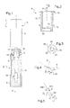
- FIG. 1 a packaging and application device 1 comprising a container 2 filled with a cosmetic product P, makeup or care, for example a mascara.
- a cosmetic product P for example a mascara.
- the device 1 further comprises an applicator 3 comprising an applicator member 10 at a first end of a rod 8, the latter being connected by its second end to a cap 9 for closing the container 2, which can for example be screwed onto this one.
- the rod 8 is in the example described of constant circular section, but the rod of the applicator could have a different section.
- the applicator rod may have a circular cross section over at least a portion of its length.
- the application member 10 is for example constituted by a brush having a metal core, twisted right or left, the bristles being clamped between the turns of the core.
- the brush is non-twisted core or if the applicator member is other. The remainder of the description applies to any application organ.
- the longitudinal axis of the applicator member 10 coincides with the longitudinal axis of the rod 8 and with that of the device 1, but the longitudinal axis of the applicator member 10 could to be otherwise oriented, and to be rectilinear or not.
- the device 1 comprises a wiper member 6, shown separately in FIG. figure 2 , of longitudinal axis X, fixed on the neck 5 of the container 2.
- the wiper member 6, shown separately in FIG. figure 2 comprises a tubular body 15 of axis X, for example symmetrical of revolution of axis X, which can be provided at its upper end, as illustrated, with a flange 16 which bears on the upper edge 17 of the neck 5 .
- the wiper member 6 may also comprise at least one attachment relief 18 for engaging the wiper member 6 in the neck 5, for example by bearing on the lower face 19 of a shoulder of the container located at the base of collar 5, as shown in figure 1 .
- This hooking relief 18 is for example an inclined rib projecting from the body 15.
- the wiper member 6 also comprises a wiper lip 20 which extends for example inside the body 15 and which defines a wiper orifice 21, which is for example circular X axis and diameter next to the stem 8.
- the inside diameter the orifice is for example 3 mm and the rod may for example have an outer diameter of 3.2 or 3.5 mm.
- the spin lip 20 is traversed by one or more slots 25 which, as can be seen in FIG. Figures 3 and 4 , are gravely connected to the orifice 21.
- the general direction T of the slot 25 at the orifice 21 is relatively relatively inclined relative to the tangent to the orifice 21 at the junction point, this tangent being substantially perpendicular to the radius R at the junction point in the case where the orifice 21 is of circular section.
- the angle ⁇ between the direction T and the tangent may be less than 40 °, as illustrated in FIG. figure 4 better than 25 °, 15 °, 10 ° or 5 °.
- At least one slot may remain relatively close to the orifice, for example being at most 4 mm from the orifice.
- the radially outermost end of the slot is for example located at a distance ⁇ from the orifice of between 0.5 and 4 mm.
- the length of at least one slot may be between 0.5 and 10 mm.
- the thickness of the lip may be, in the region of the or each slot in particular, between 0.1 and 2 mm, being constant or not.
- the slot or slots 25 may be contiguous at rest.
- the slot or slits 25 may have non-contiguous edges at rest, having been made for example with a removal of material or molded with a small gap.
- the gap i between the opposite edges of each slot varies for example from 0.1 to 1 mm, being constant or not.
- the distance d between the middle of the mouthpiece 100 and the opposite edge 101 of the slot 25, measured perpendicular to the tangent to the orifice at the mouth, may be less than or equal to 0.5 mm, better 0 , 2 mm.
- the number of slots 25 may vary, for example from one to ten, for example between 2 and 8, preferably 3 and 6.
- the slots 25 each extend angularly about the X axis on an angular stroke that is less than 360 °.
- Slots 25 may extend to body 15, as shown in FIG. figure 6 , or stay away from it, as shown in the figure 3 .
- the slots 25 may be identical, at a rotation about the X axis, or be different, the wiper member comprising for example an alternation of slots of different lengths, as illustrated in FIG. figure 7 .
- the slots 25 may extend radially outwardly as shown in FIG. figure 10 .
- a slot 25 may end with a hole 25a, as also illustrated in this figure.
- At least one slot may extend along a path that does not move monotonically away from the center of the orifice, as illustrated in FIG. figure 9 for example a path having corrugations on either side of a median line which may follow a spiral path.
- the lip 20 may have a plurality of intersecting slots, for example two slots 25 spirally extending in opposite gyratory directions as shown in FIG. figure 11 . This may result in a non-circular orifice 21, which may allow a preferential spinning of the applicator member.
- the orifice 21 may have a non-circular section, for example polygonal or oval, the rod 8 being fixed for example on the container without turning.
- the orifice 21 may have axial symmetry.
- a slot 25 can be defined between faces 120 and 121 of the lip 20 which touch or not and are parallel or not.
- the lip 20 may extend converging towards the interior of the container, as illustrated in FIGS. figures 12 and 16 , alternatively diverging towards the interior of the container, as illustrated in FIG. figure 13 .
- the wiper member 6 may be double and comprise, for example, a second wiper lip 60 above the wiper lip 20, this second wiper lip 60 possibly being able to be made with slots according to the invention.
- the second wiper lip 60 may be located under the first.
- the rod 8 may comprise an annular necking 8a to be placed at the orifice 21 in the storage configuration.
- the orifice of the latter may be larger, adapted to the diameter of the rod out narrowing 8a.
- one or both may have slots according to the invention.
- both lips may have slots, they can be superimposed or angularly offset.
- the wiper member 6 comprises an insert 70 which reduces the possibility for the lip 20 to bend upwards.
- This insert 70 is for example in the form of a ring of a relatively rigid plastic material which can be attached, for example fixed by snap-fastening, in the wiper member 6 or alternatively which can be overmolded on the material of the wiper member.
- the wiper member 6 may also be used in association with a limitation or adjustment member 80, which makes it possible to limit and / or adjust the deflection of the wiper lip 20 in at least one direction, in the species the upward movement in the example of the figure 17 .
- the member 80 may be axially movable relative to the container, for example by means of a threaded mounting skirt 81 which can be screwed more or less on the container, for example on its neck.
- the member 80 may itself have a threaded collar 82 for mounting the applicator.
- the body 80 includes an extension 83 engaged in the body 15 of the wiper member, the distance d to the wiper lip can be adjusted by the user.
- the wiper lip 20 When removing the applicator, the wiper lip 20 abuts against the lower end of the extension 83, which limits the upward movement. Depending on the value of the distance j , the displacement of the squeezing lip 20 may be greater or smaller, and it is thus possible to obtain a more or less advanced spin of the applicator member.
- the wiper member 6, shown partially is made in at least two parts, with a support portion 110 and a wiper portion 111, fixed on the support portion 110 and having the wiper lip 20.
- the support portion 110 is for example made in a material more rigid than the spin portion.
Landscapes
- Containers And Packaging Bodies Having A Special Means To Remove Contents (AREA)
- Closures For Containers (AREA)
Applications Claiming Priority (1)
| Application Number | Priority Date | Filing Date | Title |
|---|---|---|---|
| FR0756808A FR2919586B1 (fr) | 2007-07-30 | 2007-07-30 | Dispositif de conditionnement et d'application comportant un organe d'essorage pourvu d'au moins une fente non radiale. |
Publications (1)
| Publication Number | Publication Date |
|---|---|
| EP2022366A1 true EP2022366A1 (de) | 2009-02-11 |
Family
ID=39226835
Family Applications (1)
| Application Number | Title | Priority Date | Filing Date |
|---|---|---|---|
| EP08161379A Withdrawn EP2022366A1 (de) | 2007-07-30 | 2008-07-29 | Verpackungs- und Anwendungsvorrichtung, die ein Abstreifelement umfasst, das mit mindestens einem nicht-radialen Schlitz ausgestattet ist |
Country Status (3)
| Country | Link |
|---|---|
| US (1) | US20090052969A1 (de) |
| EP (1) | EP2022366A1 (de) |
| FR (1) | FR2919586B1 (de) |
Cited By (4)
| Publication number | Priority date | Publication date | Assignee | Title |
|---|---|---|---|---|
| EP2446770A1 (de) * | 2010-10-27 | 2012-05-02 | GEKA GmbH | Rechteckiger Abstreifer für Flachbürsten |
| EP2583584A3 (de) * | 2011-10-19 | 2013-12-18 | GEKA GmbH | Mehrfachabstreifer |
| EP2583582A3 (de) * | 2011-10-19 | 2013-12-18 | GEKA GmbH | Abstreifer mit federnden Abstreiferlamellen |
| EP2684485A1 (de) * | 2012-07-13 | 2014-01-15 | RND Group LLC. | Gleitwischer eines Kosmetikbehälters |
Families Citing this family (10)
| Publication number | Priority date | Publication date | Assignee | Title |
|---|---|---|---|---|
| US8272140B2 (en) | 2006-10-27 | 2012-09-25 | Group One Limited | Fluid reservoir assembly |
| FR2943512B1 (fr) | 2009-03-27 | 2011-05-27 | Oreal | Applicateur metallique. |
| FR2948542B1 (fr) | 2009-07-29 | 2011-08-26 | Clarins Lab | Dispositif de conditionnement et d'application d'un produit cosmetique et/ou dermatologique |
| JP2012019817A (ja) * | 2010-07-12 | 2012-02-02 | Tokyo Parts Kk | マスカラブラシ |
| FR2973991B1 (fr) | 2011-04-12 | 2013-05-03 | Oreal | Brosse a mascara |
| WO2014130393A1 (en) * | 2013-02-22 | 2014-08-28 | Mawi DNA Technologies LLC | Sample recovery and collection device |
| FR3028728B1 (fr) * | 2014-11-21 | 2018-01-26 | L'oreal | Dispositif de conditionnement et d'application |
| WO2017075816A1 (zh) * | 2015-11-06 | 2017-05-11 | 陈文胜 | 化妆品容器 |
| US10660419B2 (en) * | 2016-12-15 | 2020-05-26 | Elc Management Llc | Packaged skin treatment composition and method |
| FR3113571B1 (fr) * | 2020-08-25 | 2023-01-20 | Oreal | Essoreur pour récipient contenant un produit, notamment un produit cosmétique |
Citations (9)
| Publication number | Priority date | Publication date | Assignee | Title |
|---|---|---|---|---|
| US2627619A (en) * | 1947-07-29 | 1953-02-10 | Gagen Joseph Wilfrid | Nail lacquer bottle assembly, including brush wiper |
| GB2097662A (en) | 1981-05-04 | 1982-11-10 | Oreal | Serrated wiper |
| US4390298A (en) | 1981-10-21 | 1983-06-28 | Carluccio John F | Universal wiper plug for liquid cosmetic products |
| DE19744181A1 (de) | 1997-10-07 | 1999-04-08 | Geka Brush Georg Karl Gmbh | Kosmetik-Einheit |
| EP1050231A1 (de) * | 1999-05-07 | 2000-11-08 | L'oreal | Vorrichtung zum Aufbewahren und Auftragen von kosmetischen Produkten |
| US20030196672A1 (en) * | 2002-04-23 | 2003-10-23 | Mitsubishi Pencil Kabushiki Kaisha | Liquid container |
| EP1714579A1 (de) | 2005-04-19 | 2006-10-25 | L'oreal | Produktaufbewahrungs- und Ausgabevorrichtung, beispielsweise für Kosmetikartikel |
| WO2007004156A1 (en) | 2005-07-06 | 2007-01-11 | L'oreal | A packaging and applicator device including a wiper member |
| EP1772074A2 (de) | 2005-10-10 | 2007-04-11 | L'oreal | Vorrichtung zum Aufbewahren und Auftragen eines Produktes |
Family Cites Families (4)
| Publication number | Priority date | Publication date | Assignee | Title |
|---|---|---|---|---|
| US4671689A (en) * | 1984-04-11 | 1987-06-09 | L'oreal | Eyelash make-up unit |
| FR2805720B1 (fr) * | 2000-03-03 | 2002-08-16 | Oreal | Dispositif comprenant un applicateur et/ou un organe d'essorage magnetique |
| JP3854824B2 (ja) * | 2001-07-11 | 2006-12-06 | 株式会社新和製作所 | 液体化粧料塗布具 |
| US7455468B2 (en) * | 2005-12-15 | 2008-11-25 | L'oreal | Packaging and application device with adjustable wiping |
-
2007
- 2007-07-30 FR FR0756808A patent/FR2919586B1/fr not_active Expired - Fee Related
-
2008
- 2008-07-29 EP EP08161379A patent/EP2022366A1/de not_active Withdrawn
- 2008-07-29 US US12/181,805 patent/US20090052969A1/en not_active Abandoned
Patent Citations (9)
| Publication number | Priority date | Publication date | Assignee | Title |
|---|---|---|---|---|
| US2627619A (en) * | 1947-07-29 | 1953-02-10 | Gagen Joseph Wilfrid | Nail lacquer bottle assembly, including brush wiper |
| GB2097662A (en) | 1981-05-04 | 1982-11-10 | Oreal | Serrated wiper |
| US4390298A (en) | 1981-10-21 | 1983-06-28 | Carluccio John F | Universal wiper plug for liquid cosmetic products |
| DE19744181A1 (de) | 1997-10-07 | 1999-04-08 | Geka Brush Georg Karl Gmbh | Kosmetik-Einheit |
| EP1050231A1 (de) * | 1999-05-07 | 2000-11-08 | L'oreal | Vorrichtung zum Aufbewahren und Auftragen von kosmetischen Produkten |
| US20030196672A1 (en) * | 2002-04-23 | 2003-10-23 | Mitsubishi Pencil Kabushiki Kaisha | Liquid container |
| EP1714579A1 (de) | 2005-04-19 | 2006-10-25 | L'oreal | Produktaufbewahrungs- und Ausgabevorrichtung, beispielsweise für Kosmetikartikel |
| WO2007004156A1 (en) | 2005-07-06 | 2007-01-11 | L'oreal | A packaging and applicator device including a wiper member |
| EP1772074A2 (de) | 2005-10-10 | 2007-04-11 | L'oreal | Vorrichtung zum Aufbewahren und Auftragen eines Produktes |
Cited By (4)
| Publication number | Priority date | Publication date | Assignee | Title |
|---|---|---|---|---|
| EP2446770A1 (de) * | 2010-10-27 | 2012-05-02 | GEKA GmbH | Rechteckiger Abstreifer für Flachbürsten |
| EP2583584A3 (de) * | 2011-10-19 | 2013-12-18 | GEKA GmbH | Mehrfachabstreifer |
| EP2583582A3 (de) * | 2011-10-19 | 2013-12-18 | GEKA GmbH | Abstreifer mit federnden Abstreiferlamellen |
| EP2684485A1 (de) * | 2012-07-13 | 2014-01-15 | RND Group LLC. | Gleitwischer eines Kosmetikbehälters |
Also Published As
| Publication number | Publication date |
|---|---|
| FR2919586B1 (fr) | 2012-05-04 |
| FR2919586A1 (fr) | 2009-02-06 |
| US20090052969A1 (en) | 2009-02-26 |
Similar Documents
| Publication | Publication Date | Title |
|---|---|---|
| FR2919586A1 (fr) | Dispositif de conditionnement et d'application comportant un organe d'essorage pourvu d'au moins une fente non radiale. | |
| EP1053695B2 (de) | Vorrichtung zum Aufbewahren und Auftragen von kosmetischen Produkten, insbesondere für Lippenstift | |
| EP1917883B1 (de) | Applikator zum Auftragen eines Produkts auf Wimpern oder Augenbrauen | |
| EP1935279B1 (de) | Applikator zum Auftragen eines Kosmetikprodukts auf keratinhaltige Stoffe | |
| EP1593320B1 (de) | Applikator und Aufbewahrungs- bzw. Spendevorrichtung welche einen solchen Applikator enthält | |
| EP0978241B1 (de) | Vorrichtung zum Auftragen von Schminkprodukten mit einer Bürste, Verfahren zu dessen Herstellung und Auftragseinheit mit einer solchen Vorrichtung | |
| EP1477083B1 (de) | Applikator und Behälter mit einem solchen Aplikator | |
| FR2888097A1 (fr) | Dispositif de conditionnement et d'application comportant un organe d'essorage | |
| EP1247472B1 (de) | Vorrichtung zum Aufbewahren und Auftragen eines Produkts, insbesondere eines kosmetischen Produktes | |
| FR2961384B1 (fr) | Applicateur d'un produit cosmetique, de maquillage ou de soin, sur les cils ou les sourcils | |
| FR3058622B1 (fr) | Applicateur pour appliquer un produit cosmetique sur les matieres keratiniques | |
| EP1714579B1 (de) | Produktaufbewahrungs- und Ausgabevorrichtung, beispielsweise für Kosmetikartikel | |
| EP2229840A1 (de) | Instrument zum Aufbringen eines Kosmetik-, Schmink- oder Hautpflegeprodukts, und entsprechendes Herstellungsverfahren | |
| FR2855380A1 (fr) | Dispositif de conditionnement et d'application d'un produit, comportant un organe d'essorage | |
| FR2932657A1 (fr) | Brosse a mascara. | |
| FR2891708A1 (fr) | Dispositif de conditionnement et d'application d'un produit. | |
| FR3014656A1 (fr) | Applicateur d'un produit cosmetique, de maquillage ou de soin, sur les cils et/ou les sourcils | |
| FR2979807A1 (fr) | Applicateur pour appliquer un produit sur les cils ou les sourcils | |
| FR2917584A1 (fr) | Dispositif de conditionnement et d'application pour appliquer un produit sur la peau ou les levres | |
| FR2951621A1 (fr) | Dispositif comportant un applicateur de produit cosmetique ou de soin. | |
| FR2939618A1 (fr) | Applicateur pour appliquer un produit cosmetique, de maquillage ou de soin, sur les matieres keratiniques | |
| FR3026283A1 (fr) | Applicateur d'un produit cosmetique, de maquillage ou de soin, sur les cils et/ou les sourcils | |
| FR3016274A1 (fr) | Dispositif d'essorage avec levre d'essuyage a geometrie variable | |
| FR2845875A1 (fr) | Dispositif comportant un mecanisme d'entrainement d'un stick ou d'un piston mobile dans une partie de base | |
| FR2962888A1 (fr) | Applicateur et dispositif de conditionnement et d'application comportant un tel applicateur. |
Legal Events
| Date | Code | Title | Description |
|---|---|---|---|
| PUAI | Public reference made under article 153(3) epc to a published international application that has entered the european phase |
Free format text: ORIGINAL CODE: 0009012 |
|
| 17P | Request for examination filed |
Effective date: 20080729 |
|
| AK | Designated contracting states |
Kind code of ref document: A1 Designated state(s): AT BE BG CH CY CZ DE DK EE ES FI FR GB GR HR HU IE IS IT LI LT LU LV MC MT NL NO PL PT RO SE SI SK TR |
|
| AX | Request for extension of the european patent |
Extension state: AL BA MK RS |
|
| 17Q | First examination report despatched |
Effective date: 20090407 |
|
| AKX | Designation fees paid |
Designated state(s): AT BE BG CH CY CZ DE DK EE ES FI FR GB GR HR HU IE IS IT LI LT LU LV MC MT NL NO PL PT RO SE SI SK TR |
|
| STAA | Information on the status of an ep patent application or granted ep patent |
Free format text: STATUS: THE APPLICATION IS DEEMED TO BE WITHDRAWN |
|
| 18D | Application deemed to be withdrawn |
Effective date: 20150203 |