EP2022679A2 - Front- oder Heckblock eines Kraftfahrzeugs - Google Patents
Front- oder Heckblock eines Kraftfahrzeugs Download PDFInfo
- Publication number
- EP2022679A2 EP2022679A2 EP08161182A EP08161182A EP2022679A2 EP 2022679 A2 EP2022679 A2 EP 2022679A2 EP 08161182 A EP08161182 A EP 08161182A EP 08161182 A EP08161182 A EP 08161182A EP 2022679 A2 EP2022679 A2 EP 2022679A2
- Authority
- EP
- European Patent Office
- Prior art keywords
- block
- vehicle
- network
- electrical
- electrical components
- Prior art date
- Legal status (The legal status is an assumption and is not a legal conclusion. Google has not performed a legal analysis and makes no representation as to the accuracy of the status listed.)
- Granted
Links
- 238000006243 chemical reaction Methods 0.000 claims description 6
- 239000004020 conductor Substances 0.000 description 27
- 230000006870 function Effects 0.000 description 7
- 230000005540 biological transmission Effects 0.000 description 2
- 238000004140 cleaning Methods 0.000 description 2
- 238000011144 upstream manufacturing Methods 0.000 description 2
- 238000009423 ventilation Methods 0.000 description 2
- 239000006096 absorbing agent Substances 0.000 description 1
- 238000003066 decision tree Methods 0.000 description 1
- 229940082150 encore Drugs 0.000 description 1
- 230000010354 integration Effects 0.000 description 1
- 239000007788 liquid Substances 0.000 description 1
- 230000004048 modification Effects 0.000 description 1
- 238000012986 modification Methods 0.000 description 1
- 230000035939 shock Effects 0.000 description 1
- 230000009131 signaling function Effects 0.000 description 1
Images

Classifications
-
- B—PERFORMING OPERATIONS; TRANSPORTING
- B60—VEHICLES IN GENERAL
- B60R—VEHICLES, VEHICLE FITTINGS, OR VEHICLE PARTS, NOT OTHERWISE PROVIDED FOR
- B60R16/00—Electric or fluid circuits specially adapted for vehicles and not otherwise provided for; Arrangement of elements of electric or fluid circuits specially adapted for vehicles and not otherwise provided for
- B60R16/02—Electric or fluid circuits specially adapted for vehicles and not otherwise provided for; Arrangement of elements of electric or fluid circuits specially adapted for vehicles and not otherwise provided for electric constitutive elements
- B60R16/03—Electric or fluid circuits specially adapted for vehicles and not otherwise provided for; Arrangement of elements of electric or fluid circuits specially adapted for vehicles and not otherwise provided for electric constitutive elements for supply of electrical power to vehicle subsystems or for
Definitions
- the present invention generally relates to power supply networks and / or control of motor vehicles.
- the invention relates to a front or rear block of a motor vehicle, the vehicle comprising a rigid structure and a power supply network and / or control, the block being capable of being attached to said rigid structure to the front or rear of the vehicle, the block being of the type comprising a set of electrical components, a power supply harness and / or electrical components control, and at least one connection means adapted to electrically connect the beam of the block to the vehicle network.
- EP-A-0 714 812 describes a vehicle subdivided into several zones.
- the front zone has two beams interconnected by an intermediate beam.
- Each beam is electrically connected to the vehicle network by a connector.
- the interface between the front area and the rest of the vehicle is complex, both for the mounting and for the operation of the power supply network and / or control of the vehicle.
- the invention aims to provide a front or rear block whose integration with the electrical network and / or control of the vehicle is easier.
- the invention relates to a front or rear block of the aforementioned type, characterized in that the block comprises a single connection means capable of electrically connecting the beam of the block to the vehicle network, all the electrical components of the block being electrically connected to the connection means via the beam.
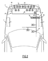
- the motor vehicle 1 represented on the figure 1 comprises, inter alia, a rigid carrier structure 2 and a front block 4 attached in one piece to the supporting structure 2.
- the carrying structure 2 comprises in particular longitudinally extending longitudinal members 6, one on the right and the other on the left of the vehicle.
- the front block 4 is rigidly fixed to the front ends of the longitudinal members 6.
- the front block 4 is here symbolized by a trapezoid drawn in dotted lines.
- the front block 4 typically comprises a rigid frame (not shown), and a plurality of equipment rigidly fixed to the frame.
- Such equipment may include, but is not limited to, the radiator, condenser, shock absorbers, a vehicle hood lock, projector washers, vehicle piping, and one or more of the following electrical components: a power train; fan 10 adapted to create a forced convection of air in contact with the radiator, the front headlamps 12, one or more available space sensors 14, one or more parking sensors 16, an ambient temperature sensor 18, a radar 20 able to detect the obstacles at the front of the vehicle, fog lights 22, a horn 24, movable flaps 26 movable to manage the ventilation of the passenger compartment of the vehicle, one or more pumps 28 provided for projecting a cleaning liquid from the outer ice of the headlamps, a speed sensor 30 forming part of the vehicle speed control device (cruise control), airbag sensors 32, etc.
- the front block also comprises a power supply and control beam 34 of the electrical components listed above.
- All the above equipment is generally mounted on the frame of the front block in the workshop of the supplier of the block, then the front block with pre-assembled equipment is attached to the front of the vehicle on the structure thereof.
- the beam 34 is mounted on the frame and connected to the various electrical components in the supplier's workshop, and then, once the front block is attached to the vehicle structure, the beam 34 is connected to the power supply network 36 and control of the vehicle.
- connection means 38 capable of electrically connecting the beam 34 to the network 36 at a single point of connection.
- the means 38 consist of an electrical connector comprising a male element 40 electrically connected to the vehicle network, and a female element 42, conjugate of the male element 40, electrically connected to the beam 34.
- the male element 40 of the connector comprises a plurality of male contacts, each connected to an electrical conductor of the network 36.
- These electrical conductors are either power supply conductors or control transfer conductors.
- the power supply conductors are connected to the power generators 44 of the vehicle, for example to the battery or the alternator.
- the control conductors carry analog or digital control information of the electrical components of the front block. They are connected to the various electronic control units 46, 48 of the vehicle.
- the female element 42 comprises a plurality of female contacts, each female contact being electrically in contact with one of the male contacts when the male element is engaged in the female element. Each female contact is also electrically connected to an electrical conductor of the beam 34.
- the beam 34 comprises a plurality of electrical power conductors, causing the electrical power from the connector 38 to the various electrical components.
- the beam 34 also includes control leads, transmitting control information to the electrical components. Some components, such as the horn 24, are connected only to power conductors. Other components, for example radar 20, are connected to both power conductors and control conductors.
- each control conductor of the beam 34 is electrically connected via a male contact and a female contact to a control conductor of the network 36.
- each power conductor of the beam 34 is connected by the intermediate of a male contact and a female contact to a power conductor of the network 36.
- the electrical connection of the beam 34 to the network 36 is extremely simple. Once the front block 4 is attached to the carrier structure of the vehicle, it suffices to engage the male element 40 of the electrical connector in the female element 42. Once the connection is made, each of the electrical components 10 to 32 is electrically connected. to the vehicle network.
- connection means 38 is an electronic box 50.
- the box 50 comprises means 52 for electrical supervision of the front block, and optionally, means 54 for analog / digital conversion and means 55 for multiplexing / demultiplexing.
- the means 56 identify the faulty components including by analyzing the evolution over time of the intensity and voltage of the current supplied to each component.
- the means 58 identify the failure in a predetermined list.
- This list can be common to all components, or be specific to each component. It can be partially common to all components.
- the list may include the following items: completely failed components, partially failed components, short circuit, overload, overvoltage, etc.
- certain electrical components of the front block are associated with electronic control units forming part of the electrical network of the vehicle 36.
- these components are the fan assembly 10, the space sensors 14, the sensors of the vehicle. parking aid 16, the radar 20, the flaps 26, the speed sensor 30, and the air bag sensors 32.
- Each of these components communicates with the corresponding control unit via the network 36 and the beam 34
- the electronic control unit manages the electrical components associated with it. Depending on the controls of the vehicle passengers, and the information available on the operation of the vehicle, the electronic control unit controls the commissioning, shutdown, or modification of the operation of the component, depending on the circumstances.
- the means 60 when they detect that such a component is faulty, communicate to the corresponding control unit, the identity of the component and the nature of the failure. In return, the control unit may return an order concerning this equipment, or any other component of the front block controlled by said control unit.
- the means 62 are capable of cutting off the power supply of each faulty electrical component.
- the means 62 receive from one of the vehicle's electrical control units a parameter representative of the state of the vehicle, specially developed for this purpose.
- this parameter indicates whether the vehicle is able to roll or not.
- the functions to be preserved are not the same depending on whether the vehicle is able to roll or is immobilized.
- the functions ensuring a good visibility to the driver (projectors) or contributing to the safety of the vehicle (airbag sensors, speed sensors for the automatic control of the speed of the vehicle , ...) are preserved.
- other functions can be cut off, such as the power supply of the pumps for cleaning the windows of the headlamps, the control of the ventilation flaps of the passenger compartment, etc.
- the means 62 will cut or not the power supply of each component. For this, the means 62 use predetermined decision trees.
- the network 36 comprises power conductors, control conductors dedicated to the transmission of analog control information, and control conductors dedicated to the transmission of digital control information.
- the various control conductors are electrically connected to the housing 50.
- the beam 34 comprises only power conductors, and analog control conductors.
- the analog control conductors of the network 36 are directly connected to the corresponding analog conductors of the beam 34.
- the digital control conductors of the network 36 are connected to the digital / analog conversion means 54, these means being able to convert the digital control signals received from the digital control conductors of the network 36 into analog control signals broadcast on the analog control conductors of the beam 34.
- the housing 50 sends the information relating to the faulty components to the electronic units of FIG. corresponding control either in the form of analogue information or in the form of digital information, as appropriate. If this information is sent in digital form, it is converted from analogue to digital by means 54.
- the digital information exchanged between the box 50 and the various electronic control units is exchanged in multiplexed form.
- the network 36 typically comprises only one digital input at the level of the housing 50.
- the housing 50 then comprises means 55 able to demultiplex the multiplexed digital signal received from the network 36, and to multiplex the digital signal broadcast on the network of the vehicle by the housing 50.
- control information is transmitted from the housing 50 to the various electrical components of the front block in analog form via the beam 34.
- the beam 34 may have different architectures.
- beam 34 has only one branch. All electrical components are connected successively, one after the other, on the beam 34 from the connection means 38.
- All equipment located downstream of the cutoff are more fueled.
- the beam 34 may also have a so-called T architecture, represented on the figure 1 .
- the beam 34 comprises a node 70, a common trunk 72 connecting the node 70 to the connection means 38, and two branches 74 extending from the node 70. Some electrical components are connected to one of the branches 74, other components being electrically connected to the other branch 74. In a variant, some components 76 may be electrically connected to the common trunk 72, between the node 70 and the connection means 38. Thus, if there is a break in the beam ( materialized by a starry symbol on the figure 1 ) on one of the branches 74, the electrical components connected to the other branch 74 remain operational. Similarly, electrical components located on the branch cut, upstream of the cutoff, that is to say between the node 70 and the cutoff point, also remain operational.
- the beam 34 has a loop architecture.
- the beam has a node 78, a common trunk 80 connecting the node 78 to the connection means 38, two branches 82 extending from the node 78, the two branches 82 being connected to each other by a second node 84.
- the two branches 82 form a loop passing through the nodes 78 and 84.
- At least some of the electrical components are electrically connected to the node 78 through both branches 82 at a time.
- all the electrical components are connected to the node 78 through the two branches 82.
- the electrical components located upstream of the cut on the cut branch 82 remain connected to the connection means 38 by said cut branch 82.
- the electrical components located downstream of the cut on the cut branch 82 are electrically connected to the other branch 82 via the node 84, and are therefore electrically connected to the connection means 38 by the branch 82 uncut.
- the front or rear block described above has many advantages.
- connection means capable of electrically connecting the beam of the block to the vehicle network, all the electrical components of the block being electrically connected to the connection means via the beam, the mounting of the block on the vehicle is greatly simplified. After bringing the block on the carrier structure of the vehicle, it is sufficient to connect the beam to the vehicle network by the single connection means.
- connection means may advantageously be an electrical connector, in which case it is sufficient to engage the male element of the connector in the conjugate female element to make the connection.
- the connection is therefore particularly simple and fast.
- connection means may also include an electronic box providing electrical supervision of the block components. This considerably simplifies the electrical architecture of the vehicle.
- This housing may comprise in particular means for identifying faulty components, means for identifying the type of failure of said failing components, and means for informing the corresponding electronic control unit of the failure of the component and the nature of the failure. These functions, in the state of the art, were distributed among the various electronic control units of the vehicle. Gathering them at the level of the housing 50 makes it possible to simplify the electrical architecture of the vehicle.
- the housing 50 may also include means for cutting off the power supply of the failing components, depending on the nature of the failure and depending on the state of the vehicle. Thus, depending on whether the vehicle is able to roll or not, certain functions are preserved or not. This allows to shut down electrical components whose operation could create dangerous situations, and which are not essential given the state of the vehicle. The operational safety of the vehicle is improved.
- the housing 50 can serve to house analog / digital conversion means so as to convert digital control signals received from the various electronic control units of the vehicle into analog control signals connected to the electrical components of the block. This further simplifies the electrical architecture of the vehicle.
- the housing 50 may comprise multiplexing / demultiplexing means able to demultiplex the signals received from the vehicle network, or to multiplex the signals broadcast to the vehicle network.
- the beam may advantageously have a T-shaped architecture, which makes it possible, in the event of the beam to be cut in one of the branches of the T, to fully preserve the operation of the components electrically connected to the other branch of the T.
- the loop architecture meanwhile, allows to preserve the operation of all electrical components, even when the beam is cut at a point.
- the block described above may have multiple variants.
- the invention has been described with respect to a front block that can be attached to the front of the vehicle. However, it is also applicable to a rear block, likely to be returned from a room at the rear of the vehicle.
- the rear block typically corresponds to the rear bumper of the vehicle. It carries electrical components such as rear registration plate lighting or a parking aid radar. It may also include motor vehicle exhaust management bodies.
- the rear block is typically attached to the rear ends of the vehicle side members.
- the beam may comprise more than two branches, for example three, four, or even more than four branches. All branches can be connected to the same node. Alternatively, the branches can be connected to different nodes distributed along the common core of the beam. Alternatively also, each branch can be subdivided into several sub-branches, extending from one or more nodes distributed along said branch.
- the beam may comprise a plurality of loops extending from the same node, or extending from several nodes distributed along the common trunk. Some loops may also be connected to nodes arranged in another loop.
- the beam may further comprise one or more branches extending from nodes located either in the common core or in one or more loops.
- connection means of the beam to the vehicle network are a connector
- the male element can be connected to the beam and the female element to the vehicle network.
- the front block described above in the embodiment comprising an electronic control unit 50 for connecting the beam to the vehicle network, makes it possible to use the same power supply and control network for all versions of the vehicle.
- the housing 50, the beam and the electrical components of the front block vary from one version to another.
- the software loaded in the various electronic control units of the vehicle may be different depending on the version.
- the electronic unit 50 may have, on the beam side of the block, one or more pending inputs. As before, it may be necessary to modify the software loaded in the electronic control units of the vehicle, without modifying the network itself.
Landscapes
- Engineering & Computer Science (AREA)
- Mechanical Engineering (AREA)
- Small-Scale Networks (AREA)
- Arrangement Or Mounting Of Propulsion Units For Vehicles (AREA)
Applications Claiming Priority (1)
| Application Number | Priority Date | Filing Date | Title |
|---|---|---|---|
| FR0756869A FR2919549B1 (fr) | 2007-08-01 | 2007-08-01 | Bloc avant ou arriere de vehicule automobile |
Publications (3)
| Publication Number | Publication Date |
|---|---|
| EP2022679A2 true EP2022679A2 (de) | 2009-02-11 |
| EP2022679A3 EP2022679A3 (de) | 2009-03-04 |
| EP2022679B1 EP2022679B1 (de) | 2011-09-14 |
Family
ID=39203293
Family Applications (1)
| Application Number | Title | Priority Date | Filing Date |
|---|---|---|---|
| EP20080161182 Ceased EP2022679B1 (de) | 2007-08-01 | 2008-07-25 | Front- oder Heckblock eines Kraftfahrzeugs |
Country Status (2)
| Country | Link |
|---|---|
| EP (1) | EP2022679B1 (de) |
| FR (1) | FR2919549B1 (de) |
Citations (1)
| Publication number | Priority date | Publication date | Assignee | Title |
|---|---|---|---|---|
| EP0714812A2 (de) | 1991-03-28 | 1996-06-05 | Yazaki Corporation | Elektrische Kabelbaumstruktur für Kraftfahrzeuge |
Family Cites Families (4)
| Publication number | Priority date | Publication date | Assignee | Title |
|---|---|---|---|---|
| JPS5298946A (en) * | 1976-02-13 | 1977-08-19 | Toyo Kogyo Co | Wiring system for automobile |
| FR2794085B1 (fr) * | 1999-05-28 | 2001-08-17 | Valeo Climatisation | Tableau de bord de vehicule avec un faisceau electrique |
| JP2002368766A (ja) * | 2001-06-05 | 2002-12-20 | Auto Network Gijutsu Kenkyusho:Kk | ワイヤーハーネスシステム |
| DE10141263B4 (de) * | 2001-08-23 | 2005-07-07 | Bayerische Motoren Werke Ag | Modular aufgebautes Fahrzeug |
-
2007
- 2007-08-01 FR FR0756869A patent/FR2919549B1/fr not_active Expired - Fee Related
-
2008
- 2008-07-25 EP EP20080161182 patent/EP2022679B1/de not_active Ceased
Patent Citations (1)
| Publication number | Priority date | Publication date | Assignee | Title |
|---|---|---|---|---|
| EP0714812A2 (de) | 1991-03-28 | 1996-06-05 | Yazaki Corporation | Elektrische Kabelbaumstruktur für Kraftfahrzeuge |
Also Published As
| Publication number | Publication date |
|---|---|
| EP2022679B1 (de) | 2011-09-14 |
| FR2919549B1 (fr) | 2010-02-19 |
| EP2022679A3 (de) | 2009-03-04 |
| FR2919549A1 (fr) | 2009-02-06 |
Similar Documents
| Publication | Publication Date | Title |
|---|---|---|
| EP1298009B1 (de) | Beleuchtungs- oder Signalierungscheinwerfer und Verfahren mit zumindest einem Scheinwerfer | |
| CA2985307C (fr) | Vehicule electrique muni d'un reseau de communication | |
| FR2787753A3 (fr) | Systeme auxiliaire de feux de signalisation de securite pour vehicule | |
| FR2578067A1 (fr) | Systeme de distribution commandee d'energie electrique dans un vehicule automobile | |
| EP2022695B1 (de) | Elektrisches Modul eines Kraftfahrzeugs sowie zugehöriges Kraftfahrzeug und Verfahren | |
| EP2022679B1 (de) | Front- oder Heckblock eines Kraftfahrzeugs | |
| EP2699452B1 (de) | Verfahren und system zur steuerung des einschaltens von bremsleuchten eines fahrzeugs und fahrzeug mit einem solchen system. | |
| FR2768982A1 (fr) | Dispositif pour eviter un freinage involontaire d'un frein electronique d'un vehicule automobile | |
| WO2011114032A1 (fr) | Dispositif de détection de déconnexion d'une batterie d'un réseau d'alimentation électrique | |
| LU82104A1 (fr) | Systeme de commande automatique | |
| FR2887394A1 (fr) | Procede et dispositif de gestion de ballast notamment pour projecteur de vehicule automobile | |
| FR2978094A1 (fr) | Dispositif de controle de feux de signalisation d'un vehicule pour la reduction temporaire de la puissance d'eclairage pendant l'arret du vehicule | |
| WO2014207351A1 (fr) | Dispositif de verrouillage d'organes electriques d'un vehicule via une communication numerique | |
| EP1170179B1 (de) | Steuerungssystem für Fahrzeugorganen | |
| FR2958600A1 (fr) | Dispositif de controle d'equipement(s) electrique(s) d'un vehicule automobile, par analyse de sa vitesse et de son environnement | |
| FR2852709A1 (fr) | Systeme de securisation de sorties de signaux de commande d'une unite de traitement d'informations | |
| EP1857942A1 (de) | Automatisches Addressierungssystem von Stellgliedern in einem Automatikfahrzeug | |
| FR2957865A1 (fr) | Dispositif pour leurrer un reseau multiplexe d'un vehicule automobile | |
| FR3081405A1 (fr) | Dispositif de communication modulaire pour vehicule. | |
| FR3020022A1 (fr) | Dispositif de commande de feux d'eclairage et/ou de signalisation a systeme de pilotage electronique dans une architecture de commande sous volant d'eclairage manuelle | |
| FR2729347A1 (fr) | Circuit de commande d'indicateurs lumineux embarques sur vehicule | |
| FR3146630A1 (fr) | Dispositif d’alimentation électrique sécurisée d’organes sécuritaires pour un véhicule automobile | |
| FR3141918A1 (fr) | Alimentation sécurisée d’organes de direction assistée électrique pour véhicule automobile | |
| FR2770303A1 (fr) | Dispositif de gestion de l'etat et du fonctionnement des equipements electriques speciaux d'un vehicule automobile | |
| FR3052710A1 (fr) | Boitier d'interface entre un vehicule automobile et un vehicule tracte |
Legal Events
| Date | Code | Title | Description |
|---|---|---|---|
| PUAI | Public reference made under article 153(3) epc to a published international application that has entered the european phase |
Free format text: ORIGINAL CODE: 0009012 |
|
| PUAL | Search report despatched |
Free format text: ORIGINAL CODE: 0009013 |
|
| AK | Designated contracting states |
Kind code of ref document: A2 Designated state(s): AT BE BG CH CY CZ DE DK EE ES FI FR GB GR HR HU IE IS IT LI LT LU LV MC MT NL NO PL PT RO SE SI SK TR |
|
| AX | Request for extension of the european patent |
Extension state: AL BA MK RS |
|
| AK | Designated contracting states |
Kind code of ref document: A3 Designated state(s): AT BE BG CH CY CZ DE DK EE ES FI FR GB GR HR HU IE IS IT LI LT LU LV MC MT NL NO PL PT RO SE SI SK TR |
|
| AX | Request for extension of the european patent |
Extension state: AL BA MK RS |
|
| 17P | Request for examination filed |
Effective date: 20090610 |
|
| 17Q | First examination report despatched |
Effective date: 20090721 |
|
| RIC1 | Information provided on ipc code assigned before grant |
Ipc: B60R 16/02 20060101AFI20101206BHEP Ipc: B60R 16/03 20060101ALI20101206BHEP |
|
| GRAP | Despatch of communication of intention to grant a patent |
Free format text: ORIGINAL CODE: EPIDOSNIGR1 |
|
| AKX | Designation fees paid |
Designated state(s): DE FR GB |
|
| GRAS | Grant fee paid |
Free format text: ORIGINAL CODE: EPIDOSNIGR3 |
|
| GRAA | (expected) grant |
Free format text: ORIGINAL CODE: 0009210 |
|
| AK | Designated contracting states |
Kind code of ref document: B1 Designated state(s): DE FR GB |
|
| REG | Reference to a national code |
Ref country code: GB Ref legal event code: FG4D Free format text: NOT ENGLISH |
|
| REG | Reference to a national code |
Ref country code: DE Ref legal event code: R096 Ref document number: 602008009735 Country of ref document: DE Effective date: 20111110 |
|
| PLBE | No opposition filed within time limit |
Free format text: ORIGINAL CODE: 0009261 |
|
| STAA | Information on the status of an ep patent application or granted ep patent |
Free format text: STATUS: NO OPPOSITION FILED WITHIN TIME LIMIT |
|
| 26N | No opposition filed |
Effective date: 20120615 |
|
| REG | Reference to a national code |
Ref country code: DE Ref legal event code: R097 Ref document number: 602008009735 Country of ref document: DE Effective date: 20120615 |
|
| REG | Reference to a national code |
Ref country code: FR Ref legal event code: PLFP Year of fee payment: 9 |
|
| REG | Reference to a national code |
Ref country code: FR Ref legal event code: PLFP Year of fee payment: 10 |
|
| PGFP | Annual fee paid to national office [announced via postgrant information from national office to epo] |
Ref country code: GB Payment date: 20170620 Year of fee payment: 10 Ref country code: FR Payment date: 20170621 Year of fee payment: 10 |
|
| PGFP | Annual fee paid to national office [announced via postgrant information from national office to epo] |
Ref country code: DE Payment date: 20170620 Year of fee payment: 10 |
|
| REG | Reference to a national code |
Ref country code: DE Ref legal event code: R119 Ref document number: 602008009735 Country of ref document: DE |
|
| GBPC | Gb: european patent ceased through non-payment of renewal fee |
Effective date: 20180725 |
|
| PG25 | Lapsed in a contracting state [announced via postgrant information from national office to epo] |
Ref country code: FR Free format text: LAPSE BECAUSE OF NON-PAYMENT OF DUE FEES Effective date: 20180731 Ref country code: GB Free format text: LAPSE BECAUSE OF NON-PAYMENT OF DUE FEES Effective date: 20180725 Ref country code: DE Free format text: LAPSE BECAUSE OF NON-PAYMENT OF DUE FEES Effective date: 20190201 |