EP2022716B1 - Vorrichtung zur Auslösung eines Gegenmassnahmeapparates - Google Patents
Vorrichtung zur Auslösung eines Gegenmassnahmeapparates Download PDFInfo
- Publication number
- EP2022716B1 EP2022716B1 EP07425454A EP07425454A EP2022716B1 EP 2022716 B1 EP2022716 B1 EP 2022716B1 EP 07425454 A EP07425454 A EP 07425454A EP 07425454 A EP07425454 A EP 07425454A EP 2022716 B1 EP2022716 B1 EP 2022716B1
- Authority
- EP
- European Patent Office
- Prior art keywords
- countermeasure
- seat
- release device
- actuating member
- retaining
- Prior art date
- Legal status (The legal status is an assumption and is not a legal conclusion. Google has not performed a legal analysis and makes no representation as to the accuracy of the status listed.)
- Active
Links
Images


Classifications
-
- B—PERFORMING OPERATIONS; TRANSPORTING
- B63—SHIPS OR OTHER WATERBORNE VESSELS; RELATED EQUIPMENT
- B63G—OFFENSIVE OR DEFENSIVE ARRANGEMENTS ON VESSELS; MINE-LAYING; MINE-SWEEPING; SUBMARINES; AIRCRAFT CARRIERS
- B63G8/00—Underwater vessels, e.g. submarines; Equipment specially adapted therefor
- B63G8/28—Arrangement of offensive or defensive equipment
- B63G8/30—Arrangement of offensive or defensive equipment of artillery or missile launching means
-
- B—PERFORMING OPERATIONS; TRANSPORTING
- B63—SHIPS OR OTHER WATERBORNE VESSELS; RELATED EQUIPMENT
- B63G—OFFENSIVE OR DEFENSIVE ARRANGEMENTS ON VESSELS; MINE-LAYING; MINE-SWEEPING; SUBMARINES; AIRCRAFT CARRIERS
- B63G8/00—Underwater vessels, e.g. submarines; Equipment specially adapted therefor
- B63G8/28—Arrangement of offensive or defensive equipment
- B63G8/34—Camouflage
Definitions
- the present invention relates to a countermeasure apparatus release device.
- Release devices are known which are fitted to a rear portion of a countermeasure (jammer or decoy) comprising a tubular body housing an apparatus (e.g. receiver or transmitter) that must be released after the countermeasure is fired into the water.
- a countermeasure jammer or decoy
- an apparatus e.g. receiver or transmitter
- the apparatus is normally housed in the cavity defined by the tubular body, and is pushed against the release device by a spring.
- the release device plugs an exit opening in the tubular body to prevent expulsion of the apparatus by the spring.
- the countermeasure is launched from launch tubes equipped with a high-pressure (200-250- or even 300-bar) compressed air cylinders to achieve the necessary range.
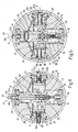
- Number 1 in Figure 1 indicates as a whole a release device for releasing an apparatus housed inside a countermeasure.
- device 1 is fitted to a rear portion 2 of the countermeasure (only shown partly), comprising a circular-section tubular body 3 housing an apparatus 5 (e.g. receiver or transmitter) that must be released after the countermeasure is fired into the water.
- an apparatus 5 e.g. receiver or transmitter
- tubular body 3 has a first end 3a connected to a connecting member 6; and a second exit end 3b having a circular exit opening 7 closed, in use, by device 1.
- Apparatus 5 is housed in the cylindrical cavity defined by tubular body 3, and is pushed against release device 1 by a spring 9 interposed between apparatus 5 and connecting member 6.
- Release device 1 plugs circular exit opening 7 to prevent expulsion of apparatus 5 by spring 9.
- device 1 comprises a disk-shaped body 11 comprising two integral portions: a first cylindrical portion 11a of radius R1, and a thinner second cylindrical portion 11b of radius R2 greater than Rl.
- First cylindrical portion 11a fits inside exit opening 7, and second portion 11b rests against end edges of tubular body 3.
- Axes A1 and A2 are perpendicular to each other.
- First and second seat 13, 15 are connected to each other by a cylindrical conduit 22 extending, coaxially with axis A1, between the bottom walls of seats 13, 15.
- First seat 13 houses in fluidtight manner the cylindrical head 24 of a piston 25 having a rod 27 extending coaxially with axis A1.
- first portion 27a of rod 27 engages hole 14b, and a second portion 27b of the rod engages cylindrical conduit 22.
- Piston 25 is movable between a first stop position ( Figure 4 ), in which cylindrical head 24 rests on plug 14, and first portion 27a of the rod projects radially by a length H from plug 14; and a second stop position ( Figure 5 ), in which cylindrical head 24 is much closer to (or rests on) the bottom wall of seat 13, and first portion 27a of the rod does not project from plug 14.
- Second seat 15 houses a programmed break member 30 fitted to plug 16, and which is broken as piston 25 moves from the first to the second stop position.
- Each seat 17, 19 houses a retaining device 32 comprising a cylindrical head 34 coaxial with axis A2 and slid axially along seat 17, 19 by a spring 36 interposed between head 34 and plug 18, 20.
- Head 34 is connected to a cylindrical rod 38 coaxial with axis A2 and engaging hole 18b, 20b.
- Cylindrical head 34 is movable axially between :
- Each seat 17, 19 has a drain conduit 40 extending from the bottom wall to conduit 22.
- drain conduit 40 When piston 25 is in the first axial stop position ( Figure 4 ), drain conduit 40 is closed by the cylindrical surface of second portion 27b of the rod; and, when piston 25 is in the second stop position ( Figure 5 ), drain conduit 40 communicates with a drain conduit 41 formed in rod 27 and for connecting seats 17, 19 to seat 15.
- rods 38 engage respective holes F ( Figure 4 ) in tubular body 3 to connect release device 1 stably to tubular body 3.
- an inclined part P (shown schematically in Figures 4, 5 ) contacts and presses portion 27a of rod 27 from the first axial stop position into the second axial stop position.
Landscapes
- Engineering & Computer Science (AREA)
- Mechanical Engineering (AREA)
- Aviation & Aerospace Engineering (AREA)
- Sampling And Sample Adjustment (AREA)
- Accommodation For Nursing Or Treatment Tables (AREA)
- Devices For Medical Bathing And Washing (AREA)
- Electrical Discharge Machining, Electrochemical Machining, And Combined Machining (AREA)
- Vending Machines For Individual Products (AREA)
- Air Bags (AREA)
Claims (8)
- Auslösevorrichtung (1) zum Auslösen eines Gegenmaßnahmegerätes (5), das in einem Hohlraum der Gegenmaßnahmeeinrichtung aufgenommen ist, wobei der Hohlraum eine Austrittsöffnung (7) aufweist, die durch die Auslösevorrichtung (1) abgeschlossen wird und über die das Gerät (5) ausgestoßen wird;
wobei die Auslösevorrichtung (1) umfasst:einen Körper (11; 11a, 11b), der die Austrittsöffnung (7) verschließt;dadurch gekennzeichnet, dass
wenigstens ein erstes Betätigungselement (27) axial zwischen einer ersten und einer zweiten Position bewegt werden kann, wenn die Gegenmaßnahmeeinrichtung abgefeuert wird; und
wenigstens ein Halteelement (38) axial zwischen einer Halteposition, in der es mit einem Abschnitt (3) der Gegenmaßnahmeeinrichtung in Eingriff ist (F, 38), und einer Auslöseposition bewegt werden kann, in der es sich von dem Abschnitt (3) der Gegenmaßnahmeeinrichtung löst, um die Auslöseeinrichtung (1) von der Gegenmaßnahmeeinrichtung zu trennen; und dass
Bewegung des ersten Betätigungselementes von der ersten Position an die zweite Position Ableiten eines Fluids aus dem Inneren einer Aufnahme (17, 19) aktiviert, um das Halteelement (38) von der Halteposition an die Auslöseposition zu bewegen. - Vorrichtung nach Anspruch 1, wobei die Aufnahme (17, 19) einen Kopf (34) aufnimmt, der, wenn das Fluid abgeleitet wird, durch den Druck einer elastischen Einrichtung (36), die im Inneren der Aufnahme aufgenommen ist, axial an der Aufnahme (17, 19) entlang bewegt werden kann;
wobei das Halteelement (38) integral mit dem Kopf (34) ausgebildet ist. - Vorrichtung nach Anspruch 1 oder 2, wobei das Betätigungselement (27) einen inneren Ableitkanal (41) aufweist, der, wenn sich das Betätigungselement an der zweiten Position befindet, mit einem Ableitkanal (40) verbunden ist, der mit der Aufnahme (17, 19) in Verbindung steht.
- Vorrichtung nach einem der vorangehenden Ansprüche, die einen Ableit-Hohlraum (15) umfasst, der das Fluid aus der Aufnahme (17. 19) aufnimmt.
- Vorrichtung nach einem der vorangehenden Ansprüche, wobei das erste Betätigungselement eine Stange (27) umfasst, die sich radial im Inneren des Körpers (11) erstreckt.
- Vorrichtung nach einem der vorangehenden Ansprüche, wobei das Halteelement (38) eine Stange (38) umfasst, die sich radial im Inneren des Körpers (11) erstreckt und die mit einem Loch (F) in Eingriff kommt, das in dem Gegenmaßnahmegerät ausgebildet ist.
- Vorrichtung nach einem der vorangehenden Ansprüche, wobei das erste Betätigungselement eine Stange (27) umfasst, die sich radial im Inneren des Körpers (11) und koaxial zu einer ersten Achse (A1) erstreckt, und das Halteelement (38) eine Stange umfasst, die sich radial im Inneren des Körpers (11) und koaxial zu einer zweiten Achse (A2) erstreckt, die quer, d.h. senkrecht, zu der ersten verläuft.
- Vorrichtung nach einem der vorangehenden Ansprüche, die ein programmiertes Bruchelement (30) umfasst, das bricht, wenn sich das erste Betätigungselement von der ersten an die zweite Position bewegt.
Priority Applications (3)
| Application Number | Priority Date | Filing Date | Title |
|---|---|---|---|
| DE602007003713T DE602007003713D1 (de) | 2007-07-24 | 2007-07-24 | Vorrichtung zur Auslösung eines Gegenmassnahmeapparates |
| AT07425454T ATE451299T1 (de) | 2007-07-24 | 2007-07-24 | Vorrichtung zur auslösung eines gegenmassnahmeapparates |
| EP07425454A EP2022716B1 (de) | 2007-07-24 | 2007-07-24 | Vorrichtung zur Auslösung eines Gegenmassnahmeapparates |
Applications Claiming Priority (1)
| Application Number | Priority Date | Filing Date | Title |
|---|---|---|---|
| EP07425454A EP2022716B1 (de) | 2007-07-24 | 2007-07-24 | Vorrichtung zur Auslösung eines Gegenmassnahmeapparates |
Publications (2)
| Publication Number | Publication Date |
|---|---|
| EP2022716A1 EP2022716A1 (de) | 2009-02-11 |
| EP2022716B1 true EP2022716B1 (de) | 2009-12-09 |
Family
ID=39110563
Family Applications (1)
| Application Number | Title | Priority Date | Filing Date |
|---|---|---|---|
| EP07425454A Active EP2022716B1 (de) | 2007-07-24 | 2007-07-24 | Vorrichtung zur Auslösung eines Gegenmassnahmeapparates |
Country Status (3)
| Country | Link |
|---|---|
| EP (1) | EP2022716B1 (de) |
| AT (1) | ATE451299T1 (de) |
| DE (1) | DE602007003713D1 (de) |
Cited By (1)
| Publication number | Priority date | Publication date | Assignee | Title |
|---|---|---|---|---|
| EP2314977A1 (de) | 2009-10-22 | 2011-04-27 | Whitehead Alenia Sistemi Subacquei S.p.A. | Abdichtung eines Abschussrohres für das Erbringen von Gegenmassnahmevorrichtungen |
Family Cites Families (5)
| Publication number | Priority date | Publication date | Assignee | Title |
|---|---|---|---|---|
| US6216626B1 (en) * | 1999-04-02 | 2001-04-17 | The United States Of America As Represented By The Secretary Of The Navy | Flow release elastomeric ejection system |
| US6336641B1 (en) * | 2000-05-01 | 2002-01-08 | The United States Of America As Represented By The Secretary Of The Navy | Break-away muzzle cap retention mechanism |
| DE10031409C1 (de) * | 2000-06-28 | 2001-09-06 | Howaldtswerke Deutsche Werft | Lager- und Ausstoßbehälter für Unterwasserschwimm- und Tauchkörper |
| US6386133B1 (en) * | 2000-09-06 | 2002-05-14 | The United States Of America As Represented By The Secretary Of The Navy | Torpedo tube shutter-pressure release |
| US6796260B1 (en) * | 2003-09-08 | 2004-09-28 | The United States Of America As Represented By The Secretary Of The Navy | Elastomeric ejection system with acoustically improved check valve |
-
2007
- 2007-07-24 EP EP07425454A patent/EP2022716B1/de active Active
- 2007-07-24 DE DE602007003713T patent/DE602007003713D1/de active Active
- 2007-07-24 AT AT07425454T patent/ATE451299T1/de not_active IP Right Cessation
Cited By (1)
| Publication number | Priority date | Publication date | Assignee | Title |
|---|---|---|---|---|
| EP2314977A1 (de) | 2009-10-22 | 2011-04-27 | Whitehead Alenia Sistemi Subacquei S.p.A. | Abdichtung eines Abschussrohres für das Erbringen von Gegenmassnahmevorrichtungen |
Also Published As
| Publication number | Publication date |
|---|---|
| DE602007003713D1 (de) | 2010-01-21 |
| EP2022716A1 (de) | 2009-02-11 |
| ATE451299T1 (de) | 2009-12-15 |
Similar Documents
| Publication | Publication Date | Title |
|---|---|---|
| KR20140016134A (ko) | 2개의 분리가능한 하위조립체를 연결하는 방아쇠식 잠금해제 장치 | |
| FI118987B (fi) | Venttiilielin | |
| EP2293007B1 (de) | Trennvorrichtung eines Auswurfmotors für eine tragbare Rakete | |
| US9562618B2 (en) | Safety device for self-propulsion gas systems | |
| CA2965935C (en) | Integrated flush-face cartridge | |
| RU2013137961A (ru) | Генератор волны сжатия и поршневая система | |
| EP4071378A1 (de) | Gasfeder | |
| US8387702B2 (en) | Multicoupler | |
| EP2022716B1 (de) | Vorrichtung zur Auslösung eines Gegenmassnahmeapparates | |
| US9512927B2 (en) | Pneumatic gate valve with integrated pressurized gas reservoir | |
| CN108457927A (zh) | 具有用于活塞杆的不受控返回的安全设备的气缸致动器 | |
| EP4320366A1 (de) | Gasfeder | |
| BR112017010022B1 (pt) | Método de acionar um dispositivo hidraulicamente operado | |
| US2465009A (en) | Concussion detonator | |
| BR102012031465A2 (pt) | Válvula de alta taxa de descarga (hrd) incorporando um mecanismo de liberação de alavanca rotativa | |
| KR100607107B1 (ko) | 유도탄 발사 장치의 배꼽분리기구 | |
| KR101264196B1 (ko) | 어뢰방어용 기만체 | |
| EP1894834B1 (de) | Schwimmer für eine auf dem Luftweg ins Meer geschossene Vorrichtung, insbesondere für ein Gegenmaßnahmemittel | |
| US2870685A (en) | Gas-operated actuating system for firearms | |
| EP3012480B1 (de) | Gasfeder mit kontrollierter druckentlastung | |
| RU2272925C1 (ru) | Заглушка реактивного двигателя | |
| KR100636058B1 (ko) | 다이어프램 파손 방지기능을 갖는 휴대용 가스레인지용가스캔 폭발방지장치 | |
| KR200357112Y1 (ko) | 공기총 | |
| CN211371088U (zh) | 多模离合器执行器 | |
| EP2019035B1 (de) | Marineschiff-Gegenmassnahmelanciervorrichtung |
Legal Events
| Date | Code | Title | Description |
|---|---|---|---|
| PUAI | Public reference made under article 153(3) epc to a published international application that has entered the european phase |
Free format text: ORIGINAL CODE: 0009012 |
|
| 17P | Request for examination filed |
Effective date: 20080912 |
|
| AK | Designated contracting states |
Kind code of ref document: A1 Designated state(s): AT BE BG CH CY CZ DE DK EE ES FI FR GB GR HU IE IS IT LI LT LU LV MC MT NL PL PT RO SE SI SK TR |
|
| AX | Request for extension of the european patent |
Extension state: AL BA HR MK RS |
|
| GRAP | Despatch of communication of intention to grant a patent |
Free format text: ORIGINAL CODE: EPIDOSNIGR1 |
|
| AKX | Designation fees paid |
Designated state(s): AT BE BG CH CY CZ DE DK EE ES FI FR GB GR HU IE IS IT LI LT LU LV MC MT NL PL PT RO SE SI SK TR |
|
| GRAS | Grant fee paid |
Free format text: ORIGINAL CODE: EPIDOSNIGR3 |
|
| GRAA | (expected) grant |
Free format text: ORIGINAL CODE: 0009210 |
|
| AK | Designated contracting states |
Kind code of ref document: B1 Designated state(s): AT BE BG CH CY CZ DE DK EE ES FI FR GB GR HU IE IS IT LI LT LU LV MC MT NL PL PT RO SE SI SK TR |
|
| REG | Reference to a national code |
Ref country code: GB Ref legal event code: FG4D |
|
| REG | Reference to a national code |
Ref country code: CH Ref legal event code: EP |
|
| REG | Reference to a national code |
Ref country code: IE Ref legal event code: FG4D |
|
| REF | Corresponds to: |
Ref document number: 602007003713 Country of ref document: DE Date of ref document: 20100121 Kind code of ref document: P |
|
| REG | Reference to a national code |
Ref country code: NL Ref legal event code: VDEP Effective date: 20091209 |
|
| PG25 | Lapsed in a contracting state [announced via postgrant information from national office to epo] |
Ref country code: FI Free format text: LAPSE BECAUSE OF FAILURE TO SUBMIT A TRANSLATION OF THE DESCRIPTION OR TO PAY THE FEE WITHIN THE PRESCRIBED TIME-LIMIT Effective date: 20091209 Ref country code: LT Free format text: LAPSE BECAUSE OF FAILURE TO SUBMIT A TRANSLATION OF THE DESCRIPTION OR TO PAY THE FEE WITHIN THE PRESCRIBED TIME-LIMIT Effective date: 20091209 Ref country code: SE Free format text: LAPSE BECAUSE OF FAILURE TO SUBMIT A TRANSLATION OF THE DESCRIPTION OR TO PAY THE FEE WITHIN THE PRESCRIBED TIME-LIMIT Effective date: 20091209 |
|
| LTIE | Lt: invalidation of european patent or patent extension |
Effective date: 20091209 |
|
| PG25 | Lapsed in a contracting state [announced via postgrant information from national office to epo] |
Ref country code: LV Free format text: LAPSE BECAUSE OF FAILURE TO SUBMIT A TRANSLATION OF THE DESCRIPTION OR TO PAY THE FEE WITHIN THE PRESCRIBED TIME-LIMIT Effective date: 20091209 Ref country code: SI Free format text: LAPSE BECAUSE OF FAILURE TO SUBMIT A TRANSLATION OF THE DESCRIPTION OR TO PAY THE FEE WITHIN THE PRESCRIBED TIME-LIMIT Effective date: 20091209 Ref country code: PL Free format text: LAPSE BECAUSE OF FAILURE TO SUBMIT A TRANSLATION OF THE DESCRIPTION OR TO PAY THE FEE WITHIN THE PRESCRIBED TIME-LIMIT Effective date: 20091209 |
|
| PG25 | Lapsed in a contracting state [announced via postgrant information from national office to epo] |
Ref country code: AT Free format text: LAPSE BECAUSE OF FAILURE TO SUBMIT A TRANSLATION OF THE DESCRIPTION OR TO PAY THE FEE WITHIN THE PRESCRIBED TIME-LIMIT Effective date: 20091209 |
|
| PG25 | Lapsed in a contracting state [announced via postgrant information from national office to epo] |
Ref country code: BG Free format text: LAPSE BECAUSE OF FAILURE TO SUBMIT A TRANSLATION OF THE DESCRIPTION OR TO PAY THE FEE WITHIN THE PRESCRIBED TIME-LIMIT Effective date: 20100309 Ref country code: RO Free format text: LAPSE BECAUSE OF FAILURE TO SUBMIT A TRANSLATION OF THE DESCRIPTION OR TO PAY THE FEE WITHIN THE PRESCRIBED TIME-LIMIT Effective date: 20091209 Ref country code: NL Free format text: LAPSE BECAUSE OF FAILURE TO SUBMIT A TRANSLATION OF THE DESCRIPTION OR TO PAY THE FEE WITHIN THE PRESCRIBED TIME-LIMIT Effective date: 20091209 Ref country code: IS Free format text: LAPSE BECAUSE OF FAILURE TO SUBMIT A TRANSLATION OF THE DESCRIPTION OR TO PAY THE FEE WITHIN THE PRESCRIBED TIME-LIMIT Effective date: 20100409 Ref country code: EE Free format text: LAPSE BECAUSE OF FAILURE TO SUBMIT A TRANSLATION OF THE DESCRIPTION OR TO PAY THE FEE WITHIN THE PRESCRIBED TIME-LIMIT Effective date: 20091209 Ref country code: ES Free format text: LAPSE BECAUSE OF FAILURE TO SUBMIT A TRANSLATION OF THE DESCRIPTION OR TO PAY THE FEE WITHIN THE PRESCRIBED TIME-LIMIT Effective date: 20100320 Ref country code: PT Free format text: LAPSE BECAUSE OF FAILURE TO SUBMIT A TRANSLATION OF THE DESCRIPTION OR TO PAY THE FEE WITHIN THE PRESCRIBED TIME-LIMIT Effective date: 20100409 |
|
| PG25 | Lapsed in a contracting state [announced via postgrant information from national office to epo] |
Ref country code: BE Free format text: LAPSE BECAUSE OF FAILURE TO SUBMIT A TRANSLATION OF THE DESCRIPTION OR TO PAY THE FEE WITHIN THE PRESCRIBED TIME-LIMIT Effective date: 20091209 Ref country code: CZ Free format text: LAPSE BECAUSE OF FAILURE TO SUBMIT A TRANSLATION OF THE DESCRIPTION OR TO PAY THE FEE WITHIN THE PRESCRIBED TIME-LIMIT Effective date: 20091209 Ref country code: SK Free format text: LAPSE BECAUSE OF FAILURE TO SUBMIT A TRANSLATION OF THE DESCRIPTION OR TO PAY THE FEE WITHIN THE PRESCRIBED TIME-LIMIT Effective date: 20091209 |
|
| PLBE | No opposition filed within time limit |
Free format text: ORIGINAL CODE: 0009261 |
|
| STAA | Information on the status of an ep patent application or granted ep patent |
Free format text: STATUS: NO OPPOSITION FILED WITHIN TIME LIMIT |
|
| PG25 | Lapsed in a contracting state [announced via postgrant information from national office to epo] |
Ref country code: GR Free format text: LAPSE BECAUSE OF FAILURE TO SUBMIT A TRANSLATION OF THE DESCRIPTION OR TO PAY THE FEE WITHIN THE PRESCRIBED TIME-LIMIT Effective date: 20100310 Ref country code: CY Free format text: LAPSE BECAUSE OF FAILURE TO SUBMIT A TRANSLATION OF THE DESCRIPTION OR TO PAY THE FEE WITHIN THE PRESCRIBED TIME-LIMIT Effective date: 20091209 |
|
| 26N | No opposition filed |
Effective date: 20100910 |
|
| PG25 | Lapsed in a contracting state [announced via postgrant information from national office to epo] |
Ref country code: DK Free format text: LAPSE BECAUSE OF FAILURE TO SUBMIT A TRANSLATION OF THE DESCRIPTION OR TO PAY THE FEE WITHIN THE PRESCRIBED TIME-LIMIT Effective date: 20091209 |
|
| PG25 | Lapsed in a contracting state [announced via postgrant information from national office to epo] |
Ref country code: MC Free format text: LAPSE BECAUSE OF NON-PAYMENT OF DUE FEES Effective date: 20100731 |
|
| PG25 | Lapsed in a contracting state [announced via postgrant information from national office to epo] |
Ref country code: IE Free format text: LAPSE BECAUSE OF NON-PAYMENT OF DUE FEES Effective date: 20100724 |
|
| PG25 | Lapsed in a contracting state [announced via postgrant information from national office to epo] |
Ref country code: MT Free format text: LAPSE BECAUSE OF FAILURE TO SUBMIT A TRANSLATION OF THE DESCRIPTION OR TO PAY THE FEE WITHIN THE PRESCRIBED TIME-LIMIT Effective date: 20091209 |
|
| REG | Reference to a national code |
Ref country code: CH Ref legal event code: PL |
|
| PG25 | Lapsed in a contracting state [announced via postgrant information from national office to epo] |
Ref country code: CH Free format text: LAPSE BECAUSE OF NON-PAYMENT OF DUE FEES Effective date: 20110731 Ref country code: LI Free format text: LAPSE BECAUSE OF NON-PAYMENT OF DUE FEES Effective date: 20110731 |
|
| PG25 | Lapsed in a contracting state [announced via postgrant information from national office to epo] |
Ref country code: HU Free format text: LAPSE BECAUSE OF FAILURE TO SUBMIT A TRANSLATION OF THE DESCRIPTION OR TO PAY THE FEE WITHIN THE PRESCRIBED TIME-LIMIT Effective date: 20100610 Ref country code: LU Free format text: LAPSE BECAUSE OF NON-PAYMENT OF DUE FEES Effective date: 20100724 |
|
| PG25 | Lapsed in a contracting state [announced via postgrant information from national office to epo] |
Ref country code: TR Free format text: LAPSE BECAUSE OF FAILURE TO SUBMIT A TRANSLATION OF THE DESCRIPTION OR TO PAY THE FEE WITHIN THE PRESCRIBED TIME-LIMIT Effective date: 20091209 |
|
| REG | Reference to a national code |
Ref country code: DE Ref legal event code: R081 Ref document number: 602007003713 Country of ref document: DE Owner name: WHITEHEAD SISTEMI SUBACQUEI S.P.A., IT Free format text: FORMER OWNER: WHITEHEAD ALENIA SISTEMI SUBACQUEI S.P.A., LIVORNO, IT Effective date: 20130325 |
|
| REG | Reference to a national code |
Ref country code: FR Ref legal event code: CD Owner name: WHITEHEAD SISTEMI SUBACQUEI S.P.A., IT Effective date: 20130422 Ref country code: FR Ref legal event code: CA Effective date: 20130422 |
|
| REG | Reference to a national code |
Ref country code: FR Ref legal event code: PLFP Year of fee payment: 10 |
|
| REG | Reference to a national code |
Ref country code: FR Ref legal event code: PLFP Year of fee payment: 11 |
|
| REG | Reference to a national code |
Ref country code: FR Ref legal event code: PLFP Year of fee payment: 12 |
|
| REG | Reference to a national code |
Ref country code: DE Ref legal event code: R081 Ref document number: 602007003713 Country of ref document: DE Owner name: LEONARDO S.P.A., IT Free format text: FORMER OWNER: WHITEHEAD SISTEMI SUBACQUEI S.P.A., LIVORNO, IT Ref country code: DE Ref legal event code: R081 Ref document number: 602007003713 Country of ref document: DE Owner name: WASS SUBMARINE SYSTEMS S.R.L., IT Free format text: FORMER OWNER: WHITEHEAD SISTEMI SUBACQUEI S.P.A., LIVORNO, IT |
|
| REG | Reference to a national code |
Ref country code: GB Ref legal event code: 732E Free format text: REGISTERED BETWEEN 20240822 AND 20240828 |
|
| REG | Reference to a national code |
Ref country code: DE Ref legal event code: R081 Ref document number: 602007003713 Country of ref document: DE Owner name: WASS SUBMARINE SYSTEMS S.R.L., IT Free format text: FORMER OWNER: LEONARDO S.P.A., ROMA, IT |
|
| REG | Reference to a national code |
Ref country code: GB Ref legal event code: 732E Free format text: REGISTERED BETWEEN 20250424 AND 20250430 |
|
| PGFP | Annual fee paid to national office [announced via postgrant information from national office to epo] |
Ref country code: DE Payment date: 20250728 Year of fee payment: 19 |
|
| PGFP | Annual fee paid to national office [announced via postgrant information from national office to epo] |
Ref country code: IT Payment date: 20250630 Year of fee payment: 19 |
|
| PGFP | Annual fee paid to national office [announced via postgrant information from national office to epo] |
Ref country code: GB Payment date: 20250722 Year of fee payment: 19 |
|
| PGFP | Annual fee paid to national office [announced via postgrant information from national office to epo] |
Ref country code: FR Payment date: 20250725 Year of fee payment: 19 |