EP2022760B1 - Cartouche de filtre pour un dispositif de filtre à eau - Google Patents
Cartouche de filtre pour un dispositif de filtre à eau Download PDFInfo
- Publication number
- EP2022760B1 EP2022760B1 EP08012817.6A EP08012817A EP2022760B1 EP 2022760 B1 EP2022760 B1 EP 2022760B1 EP 08012817 A EP08012817 A EP 08012817A EP 2022760 B1 EP2022760 B1 EP 2022760B1
- Authority
- EP
- European Patent Office
- Prior art keywords
- filter cartridge
- filter
- cartridge
- housing
- water
- Prior art date
- Legal status (The legal status is an assumption and is not a legal conclusion. Google has not performed a legal analysis and makes no representation as to the accuracy of the status listed.)
- Not-in-force
Links
Images


Classifications
-
- C—CHEMISTRY; METALLURGY
- C02—TREATMENT OF WATER, WASTE WATER, SEWAGE, OR SLUDGE
- C02F—TREATMENT OF WATER, WASTE WATER, SEWAGE, OR SLUDGE
- C02F1/00—Treatment of water, waste water, or sewage
- C02F1/001—Processes for the treatment of water whereby the filtration technique is of importance
- C02F1/003—Processes for the treatment of water whereby the filtration technique is of importance using household-type filters for producing potable water, e.g. pitchers, bottles, faucet mounted devices
-
- C—CHEMISTRY; METALLURGY
- C02—TREATMENT OF WATER, WASTE WATER, SEWAGE, OR SLUDGE
- C02F—TREATMENT OF WATER, WASTE WATER, SEWAGE, OR SLUDGE
- C02F1/00—Treatment of water, waste water, or sewage
- C02F1/006—Water distributors either inside a treatment tank or directing the water to several treatment tanks; Water treatment plants incorporating these distributors, with or without chemical or biological tanks
-
- C—CHEMISTRY; METALLURGY
- C02—TREATMENT OF WATER, WASTE WATER, SEWAGE, OR SLUDGE
- C02F—TREATMENT OF WATER, WASTE WATER, SEWAGE, OR SLUDGE
- C02F1/00—Treatment of water, waste water, or sewage
- C02F1/50—Treatment of water, waste water, or sewage by addition or application of a germicide or by oligodynamic treatment
- C02F1/505—Treatment of water, waste water, or sewage by addition or application of a germicide or by oligodynamic treatment by oligodynamic treatment
-
- C—CHEMISTRY; METALLURGY
- C02—TREATMENT OF WATER, WASTE WATER, SEWAGE, OR SLUDGE
- C02F—TREATMENT OF WATER, WASTE WATER, SEWAGE, OR SLUDGE
- C02F1/00—Treatment of water, waste water, or sewage
- C02F1/68—Treatment of water, waste water, or sewage by addition of specified substances, e.g. trace elements, for ameliorating potable water
- C02F1/685—Devices for dosing the additives
- C02F1/688—Devices in which the water progressively dissolves a solid compound
-
- C—CHEMISTRY; METALLURGY
- C02—TREATMENT OF WATER, WASTE WATER, SEWAGE, OR SLUDGE
- C02F—TREATMENT OF WATER, WASTE WATER, SEWAGE, OR SLUDGE
- C02F2101/00—Nature of the contaminant
- C02F2101/10—Inorganic compounds
- C02F2101/103—Arsenic compounds
-
- C—CHEMISTRY; METALLURGY
- C02—TREATMENT OF WATER, WASTE WATER, SEWAGE, OR SLUDGE
- C02F—TREATMENT OF WATER, WASTE WATER, SEWAGE, OR SLUDGE
- C02F2101/00—Nature of the contaminant
- C02F2101/10—Inorganic compounds
- C02F2101/20—Heavy metals or heavy metal compounds
-
- C—CHEMISTRY; METALLURGY
- C02—TREATMENT OF WATER, WASTE WATER, SEWAGE, OR SLUDGE
- C02F—TREATMENT OF WATER, WASTE WATER, SEWAGE, OR SLUDGE
- C02F2201/00—Apparatus for treatment of water, waste water or sewage
- C02F2201/002—Construction details of the apparatus
- C02F2201/006—Cartridges
-
- C—CHEMISTRY; METALLURGY
- C02—TREATMENT OF WATER, WASTE WATER, SEWAGE, OR SLUDGE
- C02F—TREATMENT OF WATER, WASTE WATER, SEWAGE, OR SLUDGE
- C02F2303/00—Specific treatment goals
- C02F2303/18—Removal of treatment agents after treatment
Definitions
- the invention relates to a filter cartridge for a water filter device, in particular for a pressureless household water filter.
- Filter cartridges for water filters which are used in particular in the household for filtering and ion exchange, are known.
- a disadvantage of this system is that forms a dead water zone, in particular as a result of the nozzle.
- a particular disadvantage is that forms a dead water zone below the filter cartridge used, which is not in direct contact with the filter medium.
- DE102005042907A discloses a filter cartridge for a water filter device in which the water after flow reversal flows into a central descending tube and finally runs out of the bottom of the cartridge mounted opening of the tube 7.
- the invention is based on the object, at least to reduce the above-mentioned disadvantages of the prior art.
- Another object of the invention is to stabilize the flow in the cartridge, which changes by the height of the water column.
- the flow at the end of the filtering process, in which there is little or no water above an inlet opening of the filter, should be increased to a desired minimum.
- Another object of the invention is to provide a filter cartridge which can be filled with various filter media.
- Another object of the invention is to provide a filter cartridge in a particularly simple manner to be able to, which allows the addition of minerals, trace elements or flavors.
- the object of the invention is already achieved by a filter cartridge for a water filter device according to claim 1.
- the invention relates to a filter cartridge for a water filter device.
- the invention relates to a filter cartridge for a non-pressurized filter, such as is used in particular in the household, in which the water is poured into a funnel above the filter cartridge and only passes through the filter due to gravity.
- the filter cartridge has a housing with at least one upper inlet and at least one lower outlet, wherein means for the flow reversal are provided between the inlet and the outlet.
- the flow reversal within the cartridge allows the water to escape from the cartridge via a defined outlet without the bottom of the filter cartridge being permeable to water.
- the housing preferably has at least one circumferential seal. This prevents water from running past the edge of the cartridge and forming dead water zones. In conjunction with the intended flow reversal, the zone which lies between the bottom and the edge of the filter cartridge as well as the container into which the cartridge is inserted remains dry.
- the seal is preferably arranged substantially at an upper edge of the filter cartridge below the inlet.
- a further chamber is provided in the housing of the filter cartridge between the means for flow reversal and the outlet of the filter cartridge.
- This chamber which preferably has a smaller volume than the rest of the filter cartridge, in particular a volume of less than one third of the filter cartridge, allows for the filter medium of the actual filter cartridge downstream water treatment.
- a medium in such a chamber, can be arranged, which adsorbs silver, which is discharged from the filter medium.
- the spout is configured tubular and arranged above a bottom of the filter cartridge. The spout is thus preferably not beyond the bottom of the filter cartridge
- the water is discharged from the filter cartridge via a tubular outlet, which can be adapted to a container of almost any desired design.
- the outlet is arranged at least 2 mm and more preferably at least 10 mm above the bottom of the filter cartridge.
- the housing of the filter cartridge is preferably filled up to a housing bottom with the filter medium substantially. Thus, dead water zones are further reduced or avoided.
- a filter cartridge for a water filter device may have at least two chambers which are at least partially separated.
- the chambers are preferably substantially fluidically parallel, that is arranged side by side.
- the two separate chambers can be filled with different filter media.
- the chambers preferably have a common housing.
- the chambers are designed as essentially juxtaposed cylinders or truncated cones, which overlap in sections.
- the resulting notch between the chambers for example, be used to integrate another inlet.
- a chamber with a medium for dispensing ions, flavors and / or trace elements can be arranged above the inlet or after the outlet or between the inlet and the outlet.
- a filter cartridge for a water filter device may include a siphon.
- the siphon is preferably arranged at the outlet of the filter cartridge and at the same time forms a flow reversal.
- the siphon is integrated in the filter cartridge.
- a siphon ensures that even at the end of the filtration process, a sufficient flow rate is present and residual water is removed as well as possible from the filter cartridge.
- the spout is preferably arranged at most 2 cm and more preferably at most 1 cm above the bottom of the filter cartridge in order to minimize the amount of residual water remaining in the cartridge.
- edge zones and below inlet openings arranged typically in the upper region of the filter cartridge form dead water zones.
- the further inlet preferably adjoins a chamber filled with a filter medium or protrudes into the chamber.
- the residual water is thus introduced directly into the chamber with the filter medium, wherein the further inlet is preferably arranged below the level with a filter medium.
- the filter cartridge according to the invention can have a tamper-evident closure at least at the outlet.
- the tamper-evident closure is preferably designed as an adhesive seal. Particularly advantageous is a combination with a flow reversal, since in such a cartridge, the water can be discharged through a defined, tubular outlet, which can be glued on a particularly simple manner, an adhesive seal.
- the filter medium may be formed such that it releases minerals or trace elements, especially calcium or magnesium.
- dietary supplements when filtering the water, dietary supplements can be added at the same time.
- the addition of such dietary supplements preferably takes place in a region arranged according to a filter stage, in particular in a further chamber.
- an arrangement with an adapter can be used in a water filter device and a cartridge insert, wherein the adapter has a preferably tubular outlet and adapter and cartridge insert together form a flow reversal.
- a separation into the two components adapter and cartridge insert makes it possible that the adapter, which contains no consuming filter medium, can be used multiple times and only the cartridge insert must be replaced.
- Fig. 1 should the essential components of a filter cartridge 1 are explained in more detail.
- the filter cartridge 1 is designed for use in a preferably to be used in the household water filter device.
- the filter cartridge 1 comprises a housing 2, which has a peripheral seal 7, with which the filter cartridge 1 used is sealed against the container of the water filter device (not shown).
- a head part with slot-shaped inlets 5 is arranged above the edge-side seal 7, a head part with slot-shaped inlets 5 is arranged.
- the filter cartridge 1 has a corrugated handle 6.
- the filter cartridge comprises a first chamber 3 and a second chamber 4, which are arranged side by side.
- the chambers 3, 4 are formed in this embodiment substantially circular cylindrical.
- Fig. 2 shows a schematic sectional view of the in Fig. 1 illustrated filter cartridge based on the above all the inner workings of the filter cartridge 1 should be explained. To recognize here is the inlet 5 in the headboard.
- substantially tubular outlet 8 can be seen.
- outlet 8 is a substantially bell-shaped chamber 9, which forms a siphon together with the outlet 8.
- the housing of the filter cartridge 1 comprises an outer housing 10 and an inner housing 11.
- the filter medium (not shown) is arranged.
- Inner and outer housing 11, 10 can be firmly connected to each other.
- the outer housing 10 is formed as an adapter, the function of the filter cartridge 1 changes in principle but not, but it is the reuse of the so designed as an adapter outer housing 11 allows.
- the bottom 12 of the inner housing includes slots which serve as an outlet. The water is introduced into the siphon via the slots.
- the bottom 13 of the outer housing 11 does not include any slots, so that the water leaves the filter cartridge 1 only via the substantially tubular outlet 8.
- the filter cartridge also comprises a further inlet 14, which is arranged below the inlet 5.
- the further inlet 14 adjoins the peripheral seal 7, which at the same time forms a channel 15.
- Residual water at the end of the filtering process can be introduced via the channel and the further inlet into the cartridge interior.
- the function of the design of the cartridge with a first chamber 3 and a second chamber 4 benefits because between the two chambers of the further inlet 14 can be arranged in a particularly simple manner.
- the further inlet 14 below the level of the filter medium (not shown) is arranged so that form no dead water zones above the filter medium, which are not in contact with the filter medium.
- the chambers 3 and 4 but only in the region of the outlet 8 are separated from each other and have no different filter medium (not shown).
- Fig. 3 the essential components of an embodiment of a siphon 16 will be explained in more detail.
- the siphon comprises a preferably substantially tubular outlet 8, above which a chamber 9 is arranged.
- the chamber 9 is essentially limited by the bottom of the outer housing 13 guided into the cartridge in the central part and the bell-shaped bottom of the inner housing substantially in the central region.
- the water Via a channel 17, which is formed in this embodiment essentially by two nested bells, the water, after it has left the inner housing 11, runs into the chamber 9.
- a downstream water treatment is arranged in the chamber 9.
- polishing which, for example, adsorbs silver ions which are released from the filter medium (not shown) or filters out heavy metals and arsenic.
- the filter cartridge 1 comprises an inlet 5 and an outlet 8 and a housing, consisting of the chambers 3 and 4.
- the water passes through the inlet 5 into the filter cartridge 1, seeps through the filter medium (not shown and leaves the sieve-shaped bottom of the chambers 3 and 4.
- the further flow of the water is marked with arrows, the flow only on the left side of the Cartridge is shown.
- the water flows after leaving the chamber 4, first to the right in the direction of the center of the cartridge.
- the water then passes through the means for reversing the flow, rising up into the chamber 9 to leave the chamber 9 defined by a preferably substantially tubular outlet 8 the cartridge.
- the flow can thus be reduced in a particularly simple manner and the residence time of the water can be set to a desired value range.
- Fig. 5 shows a further sectional view of a filter cartridge.
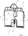
- FIG. 6 schematically shows a sectional view of an alternative embodiment of a filter cartridge 1.
- This filter cartridge 1 has an inlet 5 and an outlet 8, which is designed as a flow reversal.
- first 3 and second chambers 4 are completely separated from each other by a web 18 and can thus be filled with different filter media.
- the handle 6 extends beyond the cartridge head with the inlet 5 addition. This allows on the one hand better handling. On the other hand, compared with the previously illustrated embodiment, in which the handle extends to at most the height of the inlet, the overall height of the filter cartridge 1 is increased.
Landscapes
- Life Sciences & Earth Sciences (AREA)
- Hydrology & Water Resources (AREA)
- Engineering & Computer Science (AREA)
- Environmental & Geological Engineering (AREA)
- Water Supply & Treatment (AREA)
- Chemical & Material Sciences (AREA)
- Organic Chemistry (AREA)
- Water Treatment By Sorption (AREA)
- Treatment Of Water By Ion Exchange (AREA)
Claims (12)
- Cartouche filtrante (1) pour un dispositif de filtration d'eau, comprenant un boîtier (2) pourvu d'au moins une entrée (5) et d'au moins une sortie (8), dans lequel des moyens d'inversion d'écoulement sont prévus entre l'entrée (5) et la sortie (8), caractérisée en ce que la sortie (8) est agencée à au moins 2 mm au-dessus d'un fond (13) de la cartouche filtrante (1) et est réalisée sous la forme de tubes ne faisant pas saillie du fond (13) de la cartouche filtrante (1), par l'intermédiaire desquels l'eau est évacuée de la cartouche filtrante (1).
- Cartouche filtrante (1) selon l'une quelconque des revendications précédentes, caractérisée en ce que le boîtier (2) présente au moins un joint (7) périphérique.
- Cartouche filtrante (1) selon la revendication précédente, caractérisée en ce que le boîtier (2) est fermé au-dessous de l'ouverture périphérique.
- Cartouche filtrante (1) selon l'une quelconque des revendications précédentes, caractérisée en ce qu'une chambre (9) est agencée dans le boîtier (2) de la cartouche filtrante (1) entre les moyens d'inversion d'écoulement et la sortie.
- Cartouche filtrante (1) pour un dispositif de filtration d'eau selon l'une quelconque des revendications précédentes, la cartouche filtrante (1) étant caractérisée en ce qu'elle comprend au moins deux chambres (3, 4), lesquelles sont au moins en partie séparées.
- Cartouche filtrante (1) pour un dispositif de filtration d'eau selon l'une quelconque des revendications précédentes, caractérisée en ce qu'au moins une chambre (9) pourvue d'un milieu permettant la délivrance d'ions, d'aromatisants et/ou d'oligo-éléments est agencée au-dessus de l'entrée (5) et/ou au-dessus de la sortie (8) ou entre l'entrée (5) et la sortie (8).
- Cartouche filtrante (1) pour un dispositif de filtration d'eau selon l'une quelconque des revendications précédentes, la cartouche filtrante (1) étant caractérisée en ce qu'elle présente un siphon (16).
- Cartouche filtrante (1) pour un dispositif de filtration d'eau selon l'une quelconque des revendications précédentes, caractérisé en ce qu'une autre entrée (14) est agencée au-dessous de l'entrée (5).
- Cartouche filtrante (1) pour un dispositif de filtration d'eau selon l'une quelconque des revendications précédentes, caractérisée en ce qu'une fermeture inviolable est agencée au moins sur la sortie (8).
- Cartouche filtrante (1) pour un dispositif de filtration d'eau selon l'une quelconque des revendications précédentes, la cartouche filtrante (1) présentant un boîtier (2) rempli d'un milieu filtrant, caractérisée en ce que le milieu filtrant délivre des minéraux et/ou des oligo-éléments, en particulier du calcium et/ou du magnésium.
- Cartouche filtrante (1) pour un dispositif de filtration d'eau selon l'une quelconque des revendications précédentes, la cartouche filtrante (1) présentant au moins un boîtier (2) rempli d'un milieu filtrant, caractérisée en ce qu'une chambre (9), laquelle est traversée par de l'eau, est agencée dans le sens d'écoulement à la suite du boîtier rempli du milieu filtrant.
- Cartouche filtrante (1) pour un dispositif de filtration d'eau selon l'une quelconque des revendications précédentes, la cartouche filtrante (1) présentant au moins un boîtier (2) rempli d'un milieu filtrant, caractérisée en ce que le boîtier (2) comporte au moins deux cylindres ou cônes tronqués sensiblement agencés l'un à côté de l'autre, lesquels se chevauchent sur certaines parties.
Applications Claiming Priority (2)
| Application Number | Priority Date | Filing Date | Title |
|---|---|---|---|
| DE102007033337.6A DE102007033337C5 (de) | 2007-07-16 | 2007-07-16 | Filterkartusche für eine Wasserfiltervorrichtung |
| DE102007033339.2A DE102007033339B4 (de) | 2007-07-16 | 2007-07-16 | Filterkartusche für eine drucklose Wasserfiltervorrichtung |
Publications (3)
| Publication Number | Publication Date |
|---|---|
| EP2022760A2 EP2022760A2 (fr) | 2009-02-11 |
| EP2022760A3 EP2022760A3 (fr) | 2010-11-17 |
| EP2022760B1 true EP2022760B1 (fr) | 2019-01-16 |
Family
ID=39942889
Family Applications (1)
| Application Number | Title | Priority Date | Filing Date |
|---|---|---|---|
| EP08012817.6A Not-in-force EP2022760B1 (fr) | 2007-07-16 | 2008-07-16 | Cartouche de filtre pour un dispositif de filtre à eau |
Country Status (3)
| Country | Link |
|---|---|
| EP (1) | EP2022760B1 (fr) |
| DE (2) | DE102007033339B4 (fr) |
| ES (1) | ES2707224T3 (fr) |
Families Citing this family (8)
| Publication number | Priority date | Publication date | Assignee | Title |
|---|---|---|---|---|
| WO2012130329A1 (fr) * | 2011-04-01 | 2012-10-04 | Aktiebolaget Electrolux | Unité de filtre et dispositif de filtration d'eau comprenant une unité de filtre |
| CN103502156B (zh) | 2011-04-26 | 2016-05-25 | 碧然德有限公司 | 用于调节液体的系统和芯 |
| GB201107428D0 (en) * | 2011-05-04 | 2011-06-15 | Strix Ltd | Water treatment apparatus |
| DE102012007150A1 (de) | 2012-04-12 | 2013-10-17 | Bwt Water+More Gmbh | Kartusche zur Trinkwasseraufbereitung sowie Verfahren zur Aufbereitung von Trinkwasser |
| DE102012007149A1 (de) | 2012-04-12 | 2013-10-17 | Bwt Water+More Gmbh | Kartusche zur Trinkwasseraufbereitung sowie Verfahren zur Aufbereitung von Trinkwasser |
| DE102012105723B4 (de) * | 2012-06-28 | 2016-07-21 | Bwt Ag | Kartusche zur Trinkwasseraufbereitung |
| CN107410144B (zh) * | 2017-05-08 | 2023-03-28 | 天津市水产研究所 | 一种热带观赏鱼简易工厂化养殖系统 |
| US11027228B1 (en) * | 2018-04-30 | 2021-06-08 | Qingdao Ecopure Filter Co., Ltd. | Filtration device and filtration assembly |
Family Cites Families (23)
| Publication number | Priority date | Publication date | Assignee | Title |
|---|---|---|---|---|
| GB2197647B (en) * | 1986-08-12 | 1990-03-07 | Precision Engineering Co | Improvements in or relating to water treatment devices |
| DE8702676U1 (de) * | 1987-02-21 | 1987-06-04 | Christoph Götz & Co Teehandel oHG, 3000 Hannover | Einsatz für eine Vorrichtung zum Reinigen einer Flüssigkeit |
| DE3810441C2 (de) * | 1988-03-26 | 1994-09-08 | Brita Wasserfilter | Wasserreinigungsvorrichtung mit einem Einlauftrichter |
| DE3828008A1 (de) * | 1988-08-18 | 1990-03-08 | Bentz & Sohn Melitta | Vorrichtung zum filtern von fluessigkeiten |
| DE9003445U1 (de) * | 1990-03-23 | 1991-07-25 | Bosch-Siemens Hausgeräte GmbH, 8000 München | Wasseraufbereitungseinrichtung, insbesondere eines elektrischen Getränkebereiters |
| DE9105167U1 (de) * | 1991-04-26 | 1991-06-20 | Dietz, Ulrich, 6209 Aarbergen | Filterkartusche für Wasserfiltriertrichter |
| DE4137001A1 (de) * | 1991-11-11 | 1993-05-13 | Leifheit Ag | Haushaltswasserfilter |
| IT1278890B1 (it) * | 1995-01-13 | 1997-11-28 | I Ca S N C Lavorazione Italian | Cartuccia filtrante perfezionata |
| CA2146609C (fr) * | 1995-04-07 | 2000-04-25 | Paul Serenko | Cartouche pour le filtrage de l'eau |
| US6027639A (en) * | 1996-04-30 | 2000-02-22 | Stormwater Treatment Llc | Self-cleaning siphon-actuated radial flow filter basket |
| JPH1076251A (ja) * | 1996-09-05 | 1998-03-24 | Takashi Amano | 濾過器 |
| RU2125974C1 (ru) * | 1997-08-21 | 1999-02-10 | Закрытое акционерное общество "АКВАФОР" | Способ фильтрационной очистки жидкости и фильтр для очистки жидкости |
| DE19814008A1 (de) * | 1998-03-28 | 1999-09-30 | Brita Gmbh | Mit Granulat füllbarer Durchflußbecher |
| DE19933204A1 (de) * | 1999-07-15 | 2001-01-18 | Dieter Meyer | Wasseraufbereitungsvorrichtung |
| DE19952757A1 (de) * | 1999-11-02 | 2001-05-03 | Brita Gmbh | Filtereinrichtung für Flüssigkeiten |
| IL181065A (en) * | 2004-04-02 | 2010-11-30 | Tana Ind 1991 Ltd | Water dispenser and filter cartridge for use therein |
| DE102004026167A1 (de) * | 2004-05-28 | 2005-12-22 | Brita Gmbh | Filterkartusche und Vorrichtung zur Filtration von Flüssigkeiten |
| DE102004026176B3 (de) | 2004-05-28 | 2005-08-25 | Siemens Ag | Verfahren zum Erfassen eines zylinderindividuellen Luft/Kraftstoff-Verhältnisses bei einer Brennkraftmaschine |
| WO2006003353A1 (fr) * | 2004-07-02 | 2006-01-12 | Morphy Richards Limited | Filtre de traitement de liquide |
| EP1752421A1 (fr) * | 2005-08-12 | 2007-02-14 | Aquis Wasser-Luft-Systeme GmbH, Lindau | Dispositif pour le traitement de l'eau |
| DE102005042907A1 (de) * | 2005-09-08 | 2007-04-12 | Mecoswiss Mechanische Componenten Gmbh & Co.Kg | Wasserfilterpatrone |
| EP2251305B1 (fr) * | 2005-12-23 | 2018-01-03 | Laica S.p.A. | Cartouche filtre pour carafes |
| DE202007003927U1 (de) * | 2007-03-17 | 2007-05-24 | Aqua Select Gmbh | Anordnung zum Reinigen von Wasser |
-
2007
- 2007-07-16 DE DE102007033339.2A patent/DE102007033339B4/de active Active
- 2007-07-16 DE DE102007033337.6A patent/DE102007033337C5/de not_active Expired - Fee Related
-
2008
- 2008-07-16 ES ES08012817T patent/ES2707224T3/es active Active
- 2008-07-16 EP EP08012817.6A patent/EP2022760B1/fr not_active Not-in-force
Also Published As
| Publication number | Publication date |
|---|---|
| DE102007033337C5 (de) | 2015-12-10 |
| ES2707224T3 (es) | 2019-04-03 |
| DE102007033339B4 (de) | 2017-02-02 |
| DE102007033339A1 (de) | 2009-01-22 |
| EP2022760A2 (fr) | 2009-02-11 |
| DE102007033337B4 (de) | 2013-08-22 |
| DE102007033337A1 (de) | 2009-01-22 |
| EP2022760A3 (fr) | 2010-11-17 |
Similar Documents
| Publication | Publication Date | Title |
|---|---|---|
| EP2022760B1 (fr) | Cartouche de filtre pour un dispositif de filtre à eau | |
| DE102017001970A1 (de) | Filtervorrichtung | |
| EP1967247A1 (fr) | Filtre à air comprimé et adapteur adéquat | |
| DE1977428U (de) | Filteraggregat. | |
| EP2246174A1 (fr) | Dispositif de filtre pour matières plastiques en fusion | |
| DE102015112488A1 (de) | Lufttrocknerpatrone | |
| EP2686083B1 (fr) | Dispositif de filtration pour fluides de haute viscosité | |
| DE19648405A1 (de) | Anschlußeinheit für Großgeräte-Wasserfilter | |
| EP2754552A1 (fr) | Séparateur à vis sans fin de presse et procédé de fonctionnement du séparateur à vis sans fin de presse | |
| EP3164257B1 (fr) | Dispositif de filtration d'une matière plastique fondue | |
| AT409223B (de) | Einrichtung zur reinigung, insbesondere zur filterung, von flüssigkeiten | |
| EP3144053B1 (fr) | Récipient pour une cartouche filtrante et ensemble de filtre | |
| EP2481474B1 (fr) | Agencement d'étanchéité pour éléments de filtre céramique en forme de tiges | |
| DE10339779A1 (de) | Wasserfiltervorrichtung und Filtereinsatz | |
| DE102007063835B3 (de) | Filterkartusche für eine Wasserfiltervorrichtung | |
| DE102020130283B3 (de) | Wasseraufbereitungseinrichtung mit Anschlussbaugruppe | |
| EP2468378B1 (fr) | Dispositif de filtre | |
| DE102011111479B4 (de) | Filterplatte | |
| EP1717208B1 (fr) | Dispositif de traitement de fluides, en particulier de traitement des eaux usées, avec une pile de disques | |
| DE102008049007B4 (de) | Flüssigkeitsfilter | |
| DE102011015090B4 (de) | Filter | |
| DE102014206954A1 (de) | Kraftstofffilter einer Brennkraftmaschine | |
| DE102005048696B4 (de) | Behälter mit Filtereinsatz | |
| DE102017214718A1 (de) | Filtereinrichtung | |
| EP1302227A1 (fr) | Filtre |
Legal Events
| Date | Code | Title | Description |
|---|---|---|---|
| PUAI | Public reference made under article 153(3) epc to a published international application that has entered the european phase |
Free format text: ORIGINAL CODE: 0009012 |
|
| AK | Designated contracting states |
Kind code of ref document: A2 Designated state(s): AT BE BG CH CY CZ DE DK EE ES FI FR GB GR HR HU IE IS IT LI LT LU LV MC MT NL NO PL PT RO SE SI SK TR |
|
| AX | Request for extension of the european patent |
Extension state: AL BA MK RS |
|
| PUAL | Search report despatched |
Free format text: ORIGINAL CODE: 0009013 |
|
| AK | Designated contracting states |
Kind code of ref document: A3 Designated state(s): AT BE BG CH CY CZ DE DK EE ES FI FR GB GR HR HU IE IS IT LI LT LU LV MC MT NL NO PL PT RO SE SI SK TR |
|
| AX | Request for extension of the european patent |
Extension state: AL BA MK RS |
|
| 17P | Request for examination filed |
Effective date: 20110323 |
|
| REG | Reference to a national code |
Ref country code: DE Ref legal event code: R108 |
|
| AKX | Designation fees paid |
Designated state(s): AT BE BG CH CY LI |
|
| REG | Reference to a national code |
Ref country code: DE Ref legal event code: R108 Effective date: 20110714 |
|
| RBV | Designated contracting states (corrected) |
Designated state(s): AT BE BG CH CY CZ LI |
|
| RIN1 | Information on inventor provided before grant (corrected) |
Inventor name: PICHLER, MARKUS Inventor name: JOHANN, JUERGEN DR. Inventor name: BISSEN, MONIQUE DR. |
|
| RBV | Designated contracting states (corrected) |
Designated state(s): AT BE BG CH CY CZ DE DK EE ES FI FR GB GR HR HU IE IS IT LI LT LU LV MC MT NL NO PL PT RO SE SI SK TR |
|
| 17Q | First examination report despatched |
Effective date: 20150203 |
|
| STAA | Information on the status of an ep patent application or granted ep patent |
Free format text: STATUS: EXAMINATION IS IN PROGRESS |
|
| RIC1 | Information provided on ipc code assigned before grant |
Ipc: C02F 1/50 20060101ALN20180517BHEP Ipc: C02F 1/00 20060101AFI20180517BHEP Ipc: C02F 101/10 20060101ALN20180517BHEP Ipc: C02F 101/20 20060101ALN20180517BHEP Ipc: C02F 1/68 20060101ALN20180517BHEP |
|
| GRAP | Despatch of communication of intention to grant a patent |
Free format text: ORIGINAL CODE: EPIDOSNIGR1 |
|
| STAA | Information on the status of an ep patent application or granted ep patent |
Free format text: STATUS: GRANT OF PATENT IS INTENDED |
|
| INTG | Intention to grant announced |
Effective date: 20180622 |
|
| GRAS | Grant fee paid |
Free format text: ORIGINAL CODE: EPIDOSNIGR3 |
|
| GRAA | (expected) grant |
Free format text: ORIGINAL CODE: 0009210 |
|
| STAA | Information on the status of an ep patent application or granted ep patent |
Free format text: STATUS: THE PATENT HAS BEEN GRANTED |
|
| AK | Designated contracting states |
Kind code of ref document: B1 Designated state(s): AT BE BG CH CY CZ DE DK EE ES FI FR GB GR HR HU IE IS IT LI LT LU LV MC MT NL NO PL PT RO SE SI SK TR |
|
| REG | Reference to a national code |
Ref country code: GB Ref legal event code: FG4D Free format text: NOT ENGLISH |
|
| REG | Reference to a national code |
Ref country code: CH Ref legal event code: EP |
|
| REG | Reference to a national code |
Ref country code: IE Ref legal event code: FG4D Free format text: LANGUAGE OF EP DOCUMENT: GERMAN |
|
| REG | Reference to a national code |
Ref country code: DE Ref legal event code: R096 Ref document number: 502008016570 Country of ref document: DE |
|
| REG | Reference to a national code |
Ref country code: AT Ref legal event code: REF Ref document number: 1089567 Country of ref document: AT Kind code of ref document: T Effective date: 20190215 |
|
| REG | Reference to a national code |
Ref country code: ES Ref legal event code: FG2A Ref document number: 2707224 Country of ref document: ES Kind code of ref document: T3 Effective date: 20190403 |
|
| REG | Reference to a national code |
Ref country code: NL Ref legal event code: MP Effective date: 20190116 |
|
| REG | Reference to a national code |
Ref country code: LT Ref legal event code: MG4D |
|
| PG25 | Lapsed in a contracting state [announced via postgrant information from national office to epo] |
Ref country code: NL Free format text: LAPSE BECAUSE OF FAILURE TO SUBMIT A TRANSLATION OF THE DESCRIPTION OR TO PAY THE FEE WITHIN THE PRESCRIBED TIME-LIMIT Effective date: 20190116 |
|
| REG | Reference to a national code |
Ref country code: DE Ref legal event code: R082 Ref document number: 502008016570 Country of ref document: DE Representative=s name: AUGSPURGER - TESCH - FRIDERICHS PATENT- UND RE, DE |
|
| PG25 | Lapsed in a contracting state [announced via postgrant information from national office to epo] |
Ref country code: PT Free format text: LAPSE BECAUSE OF FAILURE TO SUBMIT A TRANSLATION OF THE DESCRIPTION OR TO PAY THE FEE WITHIN THE PRESCRIBED TIME-LIMIT Effective date: 20190516 Ref country code: LT Free format text: LAPSE BECAUSE OF FAILURE TO SUBMIT A TRANSLATION OF THE DESCRIPTION OR TO PAY THE FEE WITHIN THE PRESCRIBED TIME-LIMIT Effective date: 20190116 Ref country code: NO Free format text: LAPSE BECAUSE OF FAILURE TO SUBMIT A TRANSLATION OF THE DESCRIPTION OR TO PAY THE FEE WITHIN THE PRESCRIBED TIME-LIMIT Effective date: 20190416 Ref country code: PL Free format text: LAPSE BECAUSE OF FAILURE TO SUBMIT A TRANSLATION OF THE DESCRIPTION OR TO PAY THE FEE WITHIN THE PRESCRIBED TIME-LIMIT Effective date: 20190116 Ref country code: SE Free format text: LAPSE BECAUSE OF FAILURE TO SUBMIT A TRANSLATION OF THE DESCRIPTION OR TO PAY THE FEE WITHIN THE PRESCRIBED TIME-LIMIT Effective date: 20190116 Ref country code: FI Free format text: LAPSE BECAUSE OF FAILURE TO SUBMIT A TRANSLATION OF THE DESCRIPTION OR TO PAY THE FEE WITHIN THE PRESCRIBED TIME-LIMIT Effective date: 20190116 |
|
| PG25 | Lapsed in a contracting state [announced via postgrant information from national office to epo] |
Ref country code: BG Free format text: LAPSE BECAUSE OF FAILURE TO SUBMIT A TRANSLATION OF THE DESCRIPTION OR TO PAY THE FEE WITHIN THE PRESCRIBED TIME-LIMIT Effective date: 20190416 Ref country code: IS Free format text: LAPSE BECAUSE OF FAILURE TO SUBMIT A TRANSLATION OF THE DESCRIPTION OR TO PAY THE FEE WITHIN THE PRESCRIBED TIME-LIMIT Effective date: 20190516 Ref country code: GR Free format text: LAPSE BECAUSE OF FAILURE TO SUBMIT A TRANSLATION OF THE DESCRIPTION OR TO PAY THE FEE WITHIN THE PRESCRIBED TIME-LIMIT Effective date: 20190417 Ref country code: LV Free format text: LAPSE BECAUSE OF FAILURE TO SUBMIT A TRANSLATION OF THE DESCRIPTION OR TO PAY THE FEE WITHIN THE PRESCRIBED TIME-LIMIT Effective date: 20190116 Ref country code: HR Free format text: LAPSE BECAUSE OF FAILURE TO SUBMIT A TRANSLATION OF THE DESCRIPTION OR TO PAY THE FEE WITHIN THE PRESCRIBED TIME-LIMIT Effective date: 20190116 |
|
| REG | Reference to a national code |
Ref country code: DE Ref legal event code: R097 Ref document number: 502008016570 Country of ref document: DE |
|
| PG25 | Lapsed in a contracting state [announced via postgrant information from national office to epo] |
Ref country code: RO Free format text: LAPSE BECAUSE OF FAILURE TO SUBMIT A TRANSLATION OF THE DESCRIPTION OR TO PAY THE FEE WITHIN THE PRESCRIBED TIME-LIMIT Effective date: 20190116 Ref country code: IT Free format text: LAPSE BECAUSE OF FAILURE TO SUBMIT A TRANSLATION OF THE DESCRIPTION OR TO PAY THE FEE WITHIN THE PRESCRIBED TIME-LIMIT Effective date: 20190116 Ref country code: SK Free format text: LAPSE BECAUSE OF FAILURE TO SUBMIT A TRANSLATION OF THE DESCRIPTION OR TO PAY THE FEE WITHIN THE PRESCRIBED TIME-LIMIT Effective date: 20190116 Ref country code: CZ Free format text: LAPSE BECAUSE OF FAILURE TO SUBMIT A TRANSLATION OF THE DESCRIPTION OR TO PAY THE FEE WITHIN THE PRESCRIBED TIME-LIMIT Effective date: 20190116 Ref country code: DK Free format text: LAPSE BECAUSE OF FAILURE TO SUBMIT A TRANSLATION OF THE DESCRIPTION OR TO PAY THE FEE WITHIN THE PRESCRIBED TIME-LIMIT Effective date: 20190116 Ref country code: EE Free format text: LAPSE BECAUSE OF FAILURE TO SUBMIT A TRANSLATION OF THE DESCRIPTION OR TO PAY THE FEE WITHIN THE PRESCRIBED TIME-LIMIT Effective date: 20190116 |
|
| PLBE | No opposition filed within time limit |
Free format text: ORIGINAL CODE: 0009261 |
|
| STAA | Information on the status of an ep patent application or granted ep patent |
Free format text: STATUS: NO OPPOSITION FILED WITHIN TIME LIMIT |
|
| 26N | No opposition filed |
Effective date: 20191017 |
|
| PG25 | Lapsed in a contracting state [announced via postgrant information from national office to epo] |
Ref country code: SI Free format text: LAPSE BECAUSE OF FAILURE TO SUBMIT A TRANSLATION OF THE DESCRIPTION OR TO PAY THE FEE WITHIN THE PRESCRIBED TIME-LIMIT Effective date: 20190116 Ref country code: MC Free format text: LAPSE BECAUSE OF FAILURE TO SUBMIT A TRANSLATION OF THE DESCRIPTION OR TO PAY THE FEE WITHIN THE PRESCRIBED TIME-LIMIT Effective date: 20190116 |
|
| REG | Reference to a national code |
Ref country code: CH Ref legal event code: PL |
|
| PG25 | Lapsed in a contracting state [announced via postgrant information from national office to epo] |
Ref country code: TR Free format text: LAPSE BECAUSE OF FAILURE TO SUBMIT A TRANSLATION OF THE DESCRIPTION OR TO PAY THE FEE WITHIN THE PRESCRIBED TIME-LIMIT Effective date: 20190116 |
|
| REG | Reference to a national code |
Ref country code: BE Ref legal event code: MM Effective date: 20190731 |
|
| PG25 | Lapsed in a contracting state [announced via postgrant information from national office to epo] |
Ref country code: LU Free format text: LAPSE BECAUSE OF NON-PAYMENT OF DUE FEES Effective date: 20190716 Ref country code: BE Free format text: LAPSE BECAUSE OF NON-PAYMENT OF DUE FEES Effective date: 20190731 Ref country code: LI Free format text: LAPSE BECAUSE OF NON-PAYMENT OF DUE FEES Effective date: 20190731 Ref country code: CH Free format text: LAPSE BECAUSE OF NON-PAYMENT OF DUE FEES Effective date: 20190731 |
|
| PG25 | Lapsed in a contracting state [announced via postgrant information from national office to epo] |
Ref country code: IE Free format text: LAPSE BECAUSE OF NON-PAYMENT OF DUE FEES Effective date: 20190716 |
|
| PG25 | Lapsed in a contracting state [announced via postgrant information from national office to epo] |
Ref country code: CY Free format text: LAPSE BECAUSE OF FAILURE TO SUBMIT A TRANSLATION OF THE DESCRIPTION OR TO PAY THE FEE WITHIN THE PRESCRIBED TIME-LIMIT Effective date: 20190116 |
|
| PG25 | Lapsed in a contracting state [announced via postgrant information from national office to epo] |
Ref country code: MT Free format text: LAPSE BECAUSE OF FAILURE TO SUBMIT A TRANSLATION OF THE DESCRIPTION OR TO PAY THE FEE WITHIN THE PRESCRIBED TIME-LIMIT Effective date: 20190116 Ref country code: HU Free format text: LAPSE BECAUSE OF FAILURE TO SUBMIT A TRANSLATION OF THE DESCRIPTION OR TO PAY THE FEE WITHIN THE PRESCRIBED TIME-LIMIT; INVALID AB INITIO Effective date: 20080716 |
|
| P01 | Opt-out of the competence of the unified patent court (upc) registered |
Effective date: 20230525 |
|
| PGFP | Annual fee paid to national office [announced via postgrant information from national office to epo] |
Ref country code: GB Payment date: 20230724 Year of fee payment: 16 Ref country code: ES Payment date: 20230821 Year of fee payment: 16 Ref country code: AT Payment date: 20230718 Year of fee payment: 16 |
|
| PGFP | Annual fee paid to national office [announced via postgrant information from national office to epo] |
Ref country code: FR Payment date: 20230724 Year of fee payment: 16 |
|
| REG | Reference to a national code |
Ref country code: AT Ref legal event code: MM01 Ref document number: 1089567 Country of ref document: AT Kind code of ref document: T Effective date: 20240716 |
|
| GBPC | Gb: european patent ceased through non-payment of renewal fee |
Effective date: 20240716 |
|
| PG25 | Lapsed in a contracting state [announced via postgrant information from national office to epo] |
Ref country code: AT Free format text: LAPSE BECAUSE OF NON-PAYMENT OF DUE FEES Effective date: 20240716 |
|
| PG25 | Lapsed in a contracting state [announced via postgrant information from national office to epo] |
Ref country code: FR Free format text: LAPSE BECAUSE OF NON-PAYMENT OF DUE FEES Effective date: 20240731 |
|
| PG25 | Lapsed in a contracting state [announced via postgrant information from national office to epo] |
Ref country code: GB Free format text: LAPSE BECAUSE OF NON-PAYMENT OF DUE FEES Effective date: 20240716 |
|
| REG | Reference to a national code |
Ref country code: ES Ref legal event code: FD2A Effective date: 20250829 |
|
| PG25 | Lapsed in a contracting state [announced via postgrant information from national office to epo] |
Ref country code: ES Free format text: LAPSE BECAUSE OF NON-PAYMENT OF DUE FEES Effective date: 20240717 |
|
| PGFP | Annual fee paid to national office [announced via postgrant information from national office to epo] |
Ref country code: DE Payment date: 20250722 Year of fee payment: 18 |