EP2022836A1 - Phosphore et son procédé de fabrication, et source lumineuse l'utilisant - Google Patents
Phosphore et son procédé de fabrication, et source lumineuse l'utilisant Download PDFInfo
- Publication number
- EP2022836A1 EP2022836A1 EP08018901A EP08018901A EP2022836A1 EP 2022836 A1 EP2022836 A1 EP 2022836A1 EP 08018901 A EP08018901 A EP 08018901A EP 08018901 A EP08018901 A EP 08018901A EP 2022836 A1 EP2022836 A1 EP 2022836A1
- Authority
- EP
- European Patent Office
- Prior art keywords
- phosphor
- emission
- ppm
- raw material
- light
- Prior art date
- Legal status (The legal status is an assumption and is not a legal conclusion. Google has not performed a legal analysis and makes no representation as to the accuracy of the status listed.)
- Granted
Links
Images


Classifications
-
- C—CHEMISTRY; METALLURGY
- C09—DYES; PAINTS; POLISHES; NATURAL RESINS; ADHESIVES; COMPOSITIONS NOT OTHERWISE PROVIDED FOR; APPLICATIONS OF MATERIALS NOT OTHERWISE PROVIDED FOR
- C09K—MATERIALS FOR MISCELLANEOUS APPLICATIONS, NOT PROVIDED FOR ELSEWHERE
- C09K11/00—Luminescent materials, e.g. electroluminescent or chemiluminescent
- C09K11/08—Luminescent materials, e.g. electroluminescent or chemiluminescent containing inorganic luminescent materials
- C09K11/0883—Arsenides; Nitrides; Phosphides
-
- C—CHEMISTRY; METALLURGY
- C09—DYES; PAINTS; POLISHES; NATURAL RESINS; ADHESIVES; COMPOSITIONS NOT OTHERWISE PROVIDED FOR; APPLICATIONS OF MATERIALS NOT OTHERWISE PROVIDED FOR
- C09K—MATERIALS FOR MISCELLANEOUS APPLICATIONS, NOT PROVIDED FOR ELSEWHERE
- C09K11/00—Luminescent materials, e.g. electroluminescent or chemiluminescent
- C09K11/08—Luminescent materials, e.g. electroluminescent or chemiluminescent containing inorganic luminescent materials
- C09K11/77—Luminescent materials, e.g. electroluminescent or chemiluminescent containing inorganic luminescent materials containing rare earth metals
- C09K11/7728—Luminescent materials, e.g. electroluminescent or chemiluminescent containing inorganic luminescent materials containing rare earth metals containing europium
- C09K11/77348—Silicon Aluminium Nitrides or Silicon Aluminium Oxynitrides
-
- H—ELECTRICITY
- H10—SEMICONDUCTOR DEVICES; ELECTRIC SOLID-STATE DEVICES NOT OTHERWISE PROVIDED FOR
- H10H—INORGANIC LIGHT-EMITTING SEMICONDUCTOR DEVICES HAVING POTENTIAL BARRIERS
- H10H20/00—Individual inorganic light-emitting semiconductor devices having potential barriers, e.g. light-emitting diodes [LED]
- H10H20/80—Constructional details
- H10H20/85—Packages
- H10H20/851—Wavelength conversion means
- H10H20/8511—Wavelength conversion means characterised by their material, e.g. binder
- H10H20/8512—Wavelength conversion materials
-
- Y—GENERAL TAGGING OF NEW TECHNOLOGICAL DEVELOPMENTS; GENERAL TAGGING OF CROSS-SECTIONAL TECHNOLOGIES SPANNING OVER SEVERAL SECTIONS OF THE IPC; TECHNICAL SUBJECTS COVERED BY FORMER USPC CROSS-REFERENCE ART COLLECTIONS [XRACs] AND DIGESTS
- Y10—TECHNICAL SUBJECTS COVERED BY FORMER USPC
- Y10T—TECHNICAL SUBJECTS COVERED BY FORMER US CLASSIFICATION
- Y10T428/00—Stock material or miscellaneous articles
- Y10T428/29—Coated or structually defined flake, particle, cell, strand, strand portion, rod, filament, macroscopic fiber or mass thereof
- Y10T428/2982—Particulate matter [e.g., sphere, flake, etc.]
- Y10T428/2991—Coated
- Y10T428/2993—Silicic or refractory material containing [e.g., tungsten oxide, glass, cement, etc.]
Definitions
- the present invention relates to a phosphor used in a display such as a cathode-ray tube (CRT), a field emission display (FED), and a plasma display (PDP), and an illumination device such as a fluorescent lamp and a fluorescent display tube, and a backing light source for liquid crystal display, and a method of manufacturing therefore, and also to the light source using the phosphor.
- a display such as a cathode-ray tube (CRT), a field emission display (FED), and a plasma display (PDP)
- an illumination device such as a fluorescent lamp and a fluorescent display tube, and a backing light source for liquid crystal display, and a method of manufacturing therefore, and also to the light source using the phosphor.
- a white LED illumination has been focused as the illumination of the next generation.
- a discharge type fluorescent lamp and an incandescent bulb used as an illumination device involve problems that a harmful substance such as mercury is contained, life span is short, and heat generation is violent.
- a high luminance LED emitting light in a region of blue color and near ultraviolet/ultraviolet, which is required for the white LED illumination has been developed sequentially. Also, study and development have been actively performed on using the white LED illumination as the illumination of the next generation.
- a multi chip type system in which three primary colors of high luminance red LED, a high luminance blue LED, a high luminance green LED, are used.
- one chip system which has been developed in recent years, is given, in which LED such as a high luminance ultraviolet LED and a high luminance blue LED, and the phosphor excited by the light having an emission spectrum with a peak in the range from ultraviolet to blue color generated from the LED are combined.
- the one chip type system has a preferable characteristic as the light source for illumination, such that since it is constituted by combining an LED and the phosphor, it can be small-sized, and the light guide for mixing the emission is simplified, and in addition, the drive voltage, the optical output, and the temperature characteristic of each LED are not required to be taken into consideration, thus realizing cost reduction. Further, by using the phosphor having a broad emission spectrum, the white emission spectrum is approximated the spectrum of the sun-light, and the color rendering properties are possibly improved. This contributes to focusing on the one chip type system as the illumination of the next generation, compared with the multi chip type system.
- the blue LED with high luminance and the phosphor emitting yellow color by being excited by blue light generated from the LED are combined, and white color is obtained by using a complementary relation between the blue emission of the LED and yellow emission of the phosphor.
- the LED emitting near ultraviolet/ultraviolet light, the phosphor emitting red (R) color, the phosphor emitting green (G) color, and the phosphor emitting blue (B) color by being excited by the near ultraviolet/ultraviolet light generated from the LED are combined, and the white light is obtained by mixing the colors of the lights obtained from the phosphors of R, G, B and other phosphor.
- the white LED illumination combining the high luminance blue LED and the phosphor emitting yellow color excited by the blue light generated from the LED
- the white LED combining the high luminance blue LED and a yellow phosphor (Y, Gd) 3 (Al, Ga) 5 O 12 :Ce (expressed as YAG:Ce) is proposed.
- Y, Gd yellow phosphor
- Such a white LED has an advantage that by using the complementary relation between the blue light and the yellow light, the kind of the phosphor to be used may be reduced, compared to the system in which near ultraviolet/ultraviolet LED is used.
- the yellow phosphor YAG:Ce to be used has an excitation spectrum with a peak near the wavelength of 460nm of emission from the blue LED, thereby emitting light with high efficiency, and the white LED of high luminance can thereby be obtained.
- white color is obtained by mixing the colors of the emission from the phosphors such as R, G, B and so forth, by combining the LED emitting the near ultraviolet/ultraviolet light, the each phosphor emitting red (R), green (G), blue (B) colors excited by the near ultraviolet/ultraviolet light generated from the LED.
- a method of obtaining the white emission by mixing the emission such as the R, G, B is characterized in that an arbitrary emission color in addition to the white light can be obtained by controlling a combination and a mixing ratio of the R, G, B and also the white emission with excellent color rendering properties is obtained by the relation in a mixed state of colors not using the complementary relation but using the R, G, B.
- the light emission in the longer wavelength side of a visible light region is insufficient, resulting in a bluish white light emission.
- a red emission spectrum in the vicinity of the wavelength range from 600 nm to 700 nm is insufficient, thereby making it impossible to obtain a slightly reddish white light emission like a lamp bulb, to pose a problem of deteriorated color rendering properties.
- the yellow phosphor YAG:Ce although having an excitation band with highest efficiency in the vicinity of 460nm wavelength, the yellow phosphor YAG:Ce does not have the excitation band with excellent efficiency in a broad range. Therefore, by the variation in emission wavelength due to the variation in the light emitting element during manufacturing the blue LED, the emission wavelength of the blue LED is deviated from an optimal excitation range of the YAG:Ce-based yellow phosphor, resulting in a situation of losing a wavelength balance of blue color and yellow color. When such a situation occurs, there is the problem that the color tone of the white light obtained by synthesizing the blue light and the yellow light is changed.
- the combination of the R, G, B and so forth has no other choice but increase the mixing ratio of only the red phosphor. This causes an insufficient mixing ratio of the phosphor such as the green phosphor improving the luminance, and the white color with high luminance can not be obtained.
- the red phosphor according to the conventional technique has a sharp emission spectrum, thereby involving the problem that the color rendering properties of the white light obtained is unsatisfactory.
- the phosphor having the emission spectrum with a broad peak in the range from yellow color to red color (580nm to 680nm), and having an excellent excitation band in the longer wavelength side in the range from a near ultraviolet/ultraviolet as an excitation light to a visible light (250 nm to 550 nm).
- the phosphors are proposed such as an oxynitride glass phosphor capable of obtaining a broad emission peak in the range of yellow color to red color (for example, see patent document 1), a sialon-based phosphor (for example, see patent documents 2 and 3), and the phosphor containing nitrogen such as silicon nitride-based phosphor (for example, see patent documents 4 and 5),
- the phosphor containing nitrogen as described above has a larger ratio of convalent bonds, compared with the oxide-based phosphor, and therefore has an excellent excitation band even in the light of 400 nm or more wavelength. Therefore, the phosphor containing the nitrogen is focused as a phosphor for a white LED illumination.
- the inventors of the present invention also propose the phosphor having the emission spectrum with an excellent excitation band in the wavelength range from the near ultraviolet/ultraviolet to visible light (250 nm to 550 nm) and a broad peak in the range from yellow color to red color (580 nm to 680 nm), and containing nitrogen (Japanese Patent Application NO. 2004-55536 ).
- the phosphor proposed by the inventors of the present invention is improved in the point of having the emission spectrum with a broad peak in the range from yellow color to red color (580 nm to 680 nm) and an excellent excitation band in the longer wavelength side in the range from a near ultraviolet/ultraviolet as an excitation light to a visible light (250 nm to 550 nm), the problem is involved therein such that the emission intensity is not a satisfactory level.
- the white LED illumination is manufactured by combining the near ultraviolet/ultraviolet LED and the blue LED, the mixing ratio of only red phosphor must be increased, thereby making the green phosphor or the like insufficient to improve the luminance, and in some cases, a high luminance white color can not be obtained.
- the inventors of the present invention prepare samples of various phosphors, while pursuing the cause of not obtaining a sufficient emission intensity in the phosphor, and come to an understanding that a melting point of the raw material to be used is high, thereby making it difficult to progress a solid reaction, resulting in a non-uniform reaction.
- an object of the present invention is to provide a phosphor having an emission spectrum with a broad peak in a range from yellow color to red color (580 nm to 680 nm) and an excellent excitation band in a longer wavelength side, and improved in an emission intensity.
- One of other obj ect of the present invention is to provide a manufacturing method of the phosphor having the emission spectrum with a broad peak in the range from yellow color to red color (580 nm to 680 nm) and the excellent excitation band in the longer wavelength side in the range from a near ultraviolet/ultraviolet as an excitation light to a visible light (250 nm to 550 nm), and capable of improving the emission intensity.
- the other object of the present invention is to provide a light source using the phosphor having the emission spectrum with a broad peak in the range from yellow color to red color (580 nm to 680 nm) and the excellent excitation band in the longer wavelength side in the range from a near ultraviolet/ultraviolet as an excitation light to a visible light (250 nm to 550 nm), and capable of improving the emission intensity.
- the inventors of the present invention further study on the phosphor to accelerate a progress of the solid reaction and realize a uniform reaction, and come to the understanding that boron and/or fluorine must be contained in the phosphor, and further come to the understanding that the content of an element Fe in the phosphor must be decreased.
- element M is more than one kind of element having bivalent valency
- element A is more than one kind of element having tervalent valency selected from the group consisting of Al, Ga, In, Tl, Y, Sc, P, As
- the phosphor according to the first aspect is provided, wherein a content of the boron is not less than 0.001 wt%, and not more than 3.0 wt%.
- the phosphor according to either of the first or second aspect is provided, wherein the content of the fluorine is not less than 0.1 wt%, and not more than 3.0wt%.
- the phosphor according to any one of the first to fourth aspects wherein the element M is more than one kind of element selected from the group consisting of Mg, Ca, Sr, Ba, and Zn, the element A is more than one kind of element selected from the group consisting of Al and Ga, the element B is Si and/or Ge, and the element Z is more than one kind of element selected from the rare earth elements and the transitional metal elements.
- the phosphor according to any one of the first to fifth aspects is provided, wherein the element M is Ca, the element A is Al, the element B is Si, and the element Z is Eu.
- the phosphor according to any one of the first to sixth aspects is provided, wherein the content of the element Fe is smaller than 200 ppm.
- the phosphor according to any one of the first to seventh aspect is provided, wherein the phosphor is in a powdery state.
- the phosphor according to the eighth aspect is provided, wherein an average particle size of the phosphor is not more than 20 ⁇ m and not less than 0.1 ⁇ m.
- the phosphor according to the eighth aspect is provided, wherein a specific surface area of the phosphor powder is not more than 50 m 2 /g and not less than 0.1 m 2 /g.
- a manufacturing method of the phosphor having the structure according to any one of the first to tenth aspects comprising:
- the manufacturing method of the phosphor according to the eleventh aspect wherein the compound containing the element M, the compound containing the element A, the compound containing the element B, and the compound containing the element Z or a simple substance of the element Z, and the compound of 100 ppm or less content of Fe as the boron compound and/or the fluorine compound are used.
- the manufacturing method of the phosphor according to the twelfth aspect wherein as a compound containing the element M, the nitride of the Group II expressed by the general formula M 3 N 2 containing 100 ppm or less of element Fe (wherein the element M is more than one kind of element selected from the group consisting of Mg, Ca, Sr, Ba, and Zn.) is used.
- the manufacturing method of the phosphor according to the thirteenth aspect wherein the nitride of the Group II element manufactured by nitriding a simple substance of 2N or more containing 100 ppm or less Fe is used, in a nitrogen atmosphere or in an ammonia atmosphere at the temperature of 300°C or more.
- the manufacturing method of the phosphor according to any one of the eleventh to fourteenth aspects is provided, wherein AlN having an average particle size of 0.1 ⁇ m to 5.0 ⁇ m is used as the compound containing the element A, and Si 3 N 4 having the average particle size of 0.1 ⁇ m to 5.0 ⁇ m is used as the compound containing the element B.
- the manufacturing method of the phosphor according to any one of the eleventh to fifteenth aspects is provided, wherein the boron compound is BN and/or H 3 BO 3 .
- the manufacturing method of the phosphor according to any one of the eleventh to fifteenth aspects is provided, wherein the fluorine compound is CaF 2 and/or AlF 3 .
- the manufacturing method of the phosphor according to any one of the eleventh to seventeenth aspects wherein any one of the nitrogen atmosphere, the ammonia atmosphere, a mixed gas atmosphere of nitrogen and hydrogen, and the mixed gas atmosphere of the nitrogen and ammonia is used, in the step of obtaining a fired object by firing the mixture.
- the manufacturing method of the phosphor according to any one of the eleventh to seventeenth aspects is provided, wherein a nitrogen gas of 80% or more concentration is used, as an atmosphere gas during firing, in the step of obtaining the fired object by firing the mixture.
- the manufacturing method of the phosphor according to any one of the eleventh to nineteenth aspects is provided, wherein the mixture is fired while ventilating the atmosphere gas at the rate of 0.01L/min or more, in the step of obtaining the fired object by firing the mixture.
- the manufacturing method of the phosphor according to any one of the eleventh to twentieth aspect is provided, wherein the temperature is set at not less than 1200°C and not more than 1600°C during firing, in the step of obtaining the fired object by firing the mixture.
- the manufacturing method of the phosphor according to any one of the eleventh to twenty-first aspect is provided, wherein a pressurizing state of the atmosphere gas during firing is set at not less than 0.001 MPa and not more than 0.1 MPa.
- a light source comprising the phosphor according to any one of the first to tenth aspects, and a light emitting part.
- the light source according to the twenty-third aspect is provided, wherein a wavelength range of light emitted from the light emitting part is 250 nm to 550 nm.
- the light source according to either of the twenty-third aspect or the twenty-fourth aspect is provided, wherein an LED (light emitting diode) is used as the light emitting part.
- an LED light emitting diode
- the phosphor contains the boron and/or fluorine, a producing temperature of a liquid phase generated during firing is decreased, and the solid reaction is uniformly progressed. Therefore, the emission intensity of the phosphor can be improved.
- the phosphor contains not less than 0.001 wt% and not more than 3.0 wt% of boron, and contains not less than 0.1 wt% and not more than 3.0 wt% of fluorine, the producing temperature of the liquid phase generated during firing is decreased, and the solid reaction is more uniformly progressed, and in addition, a violent sintering can be suppressed. Therefore, the emission efficiency of the phosphor can be further improved.
- the phosphor according to any one of the eighth aspect to tenth aspect is in a powdery state, and therefore coating and filling of the phosphor can be easily performed. Further, since the average particle size of the phosphor powder is not more than 20 ⁇ m and not less than 0.1 ⁇ m, and the specific surface area is not more than 50 m 2 /g and not less than 0.1 m 2 /g, the emission efficiency can be improved.
- the manufacturing method of the phosphor of any one of the eleventh to twenty-second aspects by adding the boron compound such as BN and H 3 BO 3 as an additive agent other than the raw material of the phosphor, the producing temperature of the liquid phase generated in the process of the solid phase reaction is decreased, and the phosphor having an improved emission efficiency can be manufactured.
- the boron compound such as BN and H 3 BO 3
- the producing temperature of the liquid phase generated in the process of the solid phase reaction can be decreased, and the phosphor having the improved efficiency can be manufactured.
- the manufacturing method of the phosphor of the fifteenth aspect by using AlN and Si 3 N 4 with average particle size (D50) from 0.1 ⁇ m to 10.0 ⁇ m, the phosphor with particle size suitable for coating and filling, and further suitable for improving the emission intensity can be manufactured.
- D50 average particle size
- the phosphor capable of suppressing adsorption of the oxygen during firing and decreasing the oxygen concentration of the phosphor and having suitable particle size for improving the emission intensity can be manufactured.
- the light source according to any one of the twenty-third to twenty-fifth aspects emits light, having the excitation band in a predetermined broad wavelength range (250 nm to 550 nm) of the light emitted from the light emitting part (corresponding to LED according to the twenty-fifth aspect). Therefore, by combining the aforementioned phosphors and the light emitting part, the light source with high emission efficiency emitting the visible light or the white light can be obtained.
- the preferred embodiments of the present invention provide a phosphor having an emission spectrum with a broad peak of 50 nm or more half value width in a range from yellow color to red color (580 nm to 680 nm) and a flat and highly efficient excitation band, which is the range from the near ultraviolet/ultraviolet as an excitation light to visible light (250 nm to 550 nm) on the longer wavelength side, and further capable of obtaining an excellent emission intensity by containing boron and/or fluorine in the phosphor, and a manufacturing method therefore.
- the phosphor having not less than 0.001 wt% and not more than 3.0 wt% of boron content excellent emission characteristics can be obtained.
- the boron content is more preferably in the range from 0.05 wt% to 2.0wt%, and further preferably in the range from 0.15wt% to 0.35wt%.
- the boron content is not more than 3. 0 wt%, sintering does not become violent, thereby not reducing the emission characteristic in a pulverizing process. Further, when not more than 3.0 wt% of boron is contained, a matrix structure exhibiting an excellent emission intensity can be maintained, and this is considered to be preferable. Also, when the boron content is not less than 0.001 wt%, the liquid phase is sufficiently produced, and a desired effect can be obtained.
- the excellent emission intensity can be obtained. More preferably, the fluorine content is in the range from 0.01 wt% to 2.0 wt%. Detailed reasons are not clarified. However, the cause is also considered as follows. A lot of nitrides have generally high melting points, thereby hardly generating the liquid phase during the solid reaction, preventing the reaction from progressing.
- the producing temperature of the liquid phase is decreased, thereby easily generating the liquid phase, accelerating the reaction, and further making the solid reaction uniformly progress, and the phosphor having the excellent emission characteristic can be obtained.
- the fluorine content is not more than 3.0 wt%
- the sintering does not become violent and the emission characteristic is not reduced in the pulverizing process. Therefore, the desired effect can be obtained.
- an impurity phase not contributing to the light emission is not generated, thereby not inviting a reduction in the emission characteristic, and this is considered to be preferable.
- the fluorine content is not less than 0.1 wt%, the liquid phase is sufficiently generated, and the desired effect can be obtained.
- the phosphor according to this example is expressed by the composition formula MmAaBbOoNn:Z.
- the element M is more than one kind of element having bivalent valency
- the element A is more than one kind of element having tervalent valency selected from the group consistsing of Al, Ga, In, Tl, Y, Sc, P, As, Sb, and Bi
- the element B is more than one kind of element having tetravalent valency
- O oxygen
- N nitrogen
- element Z is more than one kind of element selected from rare earth elements or transitional metal elements.
- the phosphor of the composition formula MmAaBbOoNn:Z has a chemically stable composition, the impurity phase not contributing to the light emission is hardly generated in the phosphor, thus suppressing the deterioration in the emission characteristic to realize a preferable structure.
- the element M is the element having + bivalent valency
- the element A is the element having + tervalent valency
- the element B the element having + tetravalent valency
- oxygen is the element having - bivalent valency
- the aforementioned phosphor sometimes contains the oxygen.
- the oxygen in this case is considered to be the oxygen initially contained in the raw material and the oxygen adhered to the surface of the raw material, and the oxygen mixed in resulting from the oxidization of the surface of the raw material during mixing and firing the raw materials, and the oxygen adsorbed on the surface of the phosphor after firing.
- the oxygen of 3.0 wt% or less is contained with respect to the mass of the phosphor.
- the oxygen content of the phosphor has an upper limit set at the aforementioned 3.0 wt%, thereby being set at not more than this upper limit value.
- the element M is at least more than one kind of element selected from the group consisting of Be, Mg, Ca, Sr, Ba, Zn, Cd, and Hg, further preferably is more than one kind of element selected from the group consisting of Mg, Ca, Sr, Ba, and Zn, and most preferably is Ca.
- the element A is at least more than one kind of element having tervalent valency selected from the group consisting of Al, Ga, In, Tl, Y, Sc, P, As, Sb, and Bi, further preferably is more than one kind of element selected from Al and Ga, and most preferably is Al.
- Al is easily available at a low cost, with small environmental load, and preferable.
- AlN which is a nitride, is used as a thermoelectric material and a structural material generally used.
- the element B is more than one kind of element having tetravalent valency selected from the group consisting of C, Si, Ge, Sn, Ti, Hf, Mo, W, Cr, Pb, and Zr, further preferably is Si and/or Ge, and most preferably is Si.
- Si is easily available at a low cost, with small environmental load, and preferable.
- Si 3 N 4 which is a nitride, is used as the thermoelectric material and the structural material generally used.
- the element Z is more than one kind of element selected from the rare earth elements and the transitional metal elements.
- the light emission of the phosphor has the emission spectrum with a broad half value width.
- the element Z is preferably at least more than one kind of element selected from the group consisting of Eu, Mn, Sm, and Ce. Out of these elements, when Eu is used as the element Z, the phosphor exhibits a high emission efficiency in the range from orange color to red color, and the spectrum with a broad half value width of 50 nm or more can be obtained. Therefore, Eu is more preferable as the activator of the phosphor used in the illumination device and the light emitting device.
- the phosphor having the light emission with different wavelength can be obtained.
- the amount of the element Z to be added is in such a range as satisfying the molar ratio of the element M to the element Z, z/(m + z), being in the range from 0.0001 to 0.5.
- the molar ratio z/ (m + z) of the element M and the activator Z is within the aforementioned range, the deterioration in the emission efficiency resulting from the concentration quenching due to an excessive content of the activator can be avoided, and meanwhile, the deterioration in the emission efficiency resulting from insufficient emission contributing atoms due to too little content of the activator can also be avoided.
- the value of the aforementioned z/(m + z) is in the range from 0.005 to 0.1.
- an optimal value of the aforementioned z/(m + z) is slightly fluctuated by the kind of the activator Z and the kind of the element M.
- the peak wavelength of the emission spectrum of the phosphor can be set by shifting, which is useful for adjusting the luminance.
- the average particle size (D50) of the phosphor powder is not more than 20 ⁇ m. This is because by setting the average particle size (the average particle size in this invention refers to a median diameter (D50) .) at not more than 20 ⁇ m, and further preferably set at not less than 3 ⁇ m and not more than 15 ⁇ m, the surface area per unit weight of the powder can be secured, and the deterioration in the luminance can be avoided, because the light emission in the phosphor powder is considered to occur on the surface of the particle.
- the powder is formed into paste, and when the paste thus formed is applied to the light emitting element or the like also, the density of the powder can be heightened, and from this viewpoint also, the deterioration in the luminance can be avoided.
- the average particle size of the phosphor powder in this example is preferably set at not less than 0.1 ⁇ m and not more than 20 ⁇ m.
- the nitride and oxide of each of them and the compound of any one of them may be used as the raw materials of the element M (+ bivalent valency), the element A (+ tervalent valency), and the element B (+ tetravalent valency).
- the nitride (M 3 N 2 ) and the oxide (MO) of the element M, and the nitride (AN, B 3 N 4 ) of the element A and the element B may be used and mixed. Then, by controlling the blending ratio of both of the nitride and the oxide, an amount of oxygen and an amount of nitrogen in the phosphor can be controlled, without changing the value of m.
- the nitride and the oxide are not limited to the compound obtained by combining with only oxygen and the compound obtained by combining with only nitrogen, but for example, refers to the compound having the oxygen and the element, such as carbonate acid salt and oxalic acid salt, which are decomposed to become substantially oxide during firing, and the nitride also refers to the compound having the element and the nitrogen.
- the emission characteristic was improved by adding a boron compound and a fluorine compound as additive agents.
- the boron compound such as BN, H 3 BO 3 , B 2 O 6 , B 2 O 3 , and BCl 3 , may be added to obtain not more than 3.0 wt% of the boron in the sample after firing, and out of these elements, BN and H 3 BO 3 are preferable.
- Such boron compounds may be mixed for use.
- the boron compound has high thermal conductivity. Therefore, by adding the boron compound to the raw material, a uniform temperature distribution of the raw material during firing is obtained, and it is estimated that the emission characteristic is improved to accelerate the solid phase reaction.
- the boron compound can be added to the raw material in such a manner that it is added together with the raw materials during mixing so as to be mixed therein.
- the fluorine compound such as CaF 2 , AlF 3 , EuF 2 , EuF 3 is added to obtain not more than 3.0 wt% of fluorine in the sample after firing.
- fluorine compounds have low melting points compared to those of raw materials, AlN and Si 3 N 4 , thereby easily generating a liquid phase. Therefore, by covering the surface of the surface of the particle of the raw material, it appears that diffusion of atoms can be accelerated, and the emission characteristic is thereby improved.
- the fluorine compound obtained by combining the fluorine and calcium, the fluorine and aluminum, and the fluorine and europium is preferably added to the phosphor in which the element M is Ca, the element A is Al, the element B is Si, and the element Z is Eu, because the same element is contained therein as the element having the aforementioned composition formula.
- fluorine compounds may also be mixed for use.
- Amounts of the boron and the fluorine to be added to such raw materials, and contents of the boron and fluorine after firing are not always matched. This is because some of the boron and the fluorine is flown during firing, and therefore the content thereof becomes smaller than that at the time of addition of the raw materials, or a slight amount of boron and fluorine is contained in each raw material also, and therefore the content thereof becomes larger than that at the time of adding the raw materials. Note that for convenience of explanation, the oxygen in the composition formula is omitted in the explanation given hereunder.
- Each nitride raw material of the element M, the element A, and the element B may be a commercially available raw material. However, higher purity is more preferable, and therefore preferably the nitride raw material of 2N or more, and more preferably 3N or more is prepared. Further, it becomes possible to prepare the phosphor with excellent emission efficiency, by using the raw material having not more than 100 ppm of element Fe contained therein, as the nitride raw material of each element.
- the nitride of the element M such as conventionally available Ca 3 N 2 contains the element Fe of about 250 ppm.
- the nitride raw material of the element M of the phosphor according to the present invention is used, which is manufactured by the following method, for example.
- a simple substance of the element M of 2N or more and having the content of the element Fe of 100 ppm or less is prepared.
- Some of simple substances of the alkali-earth metal have oil films on the surface which are stuck during storage. Therefore, the surface of the simple substance of alkali-earth metal is washed with organic solvent in an inert gas atmosphere.
- the metal body thus washed is heated and nitrided at the temperature of 300°C or more in the atmosphere of nitrogen or ammonia, to thereby manufacture the nitride.
- a vessel or a crucible used at the time of nitriding is the vessel having a small content of the element Fe, and specifically a BN crucible with high purity is preferable.
- a heating temperature for nitriding is not less than 700°C, because the nitriding is accelerated by a higher temperature.
- the nitride of the element M thus obtained may be pulverized to not more than 100 ⁇ m degree of particle for use.
- the nitride of the element A and the nitride of the element B are also obtained by nitriding the metal element in the same method.
- the nitride of the element A such as AlN
- even the conventionally available one has the content of the element Fe of about 10 ppm or less, and therefore such a nitride of the element A may be used.
- the conventionally available one has the content of the element Fe of about 50 ppm or less, and therefore such a nitride of the element B may also be used.
- the average particle size desired for the phosphor is preferably from 0.1 ⁇ m to 20.0 ⁇ m, and more preferably from 3.0 ⁇ m to 15.0 ⁇ m. Therefore, from the viewpoint of controlling the particle size of the phosphor powder after firing, it is preferable to set the average particle size of each raw material at 0.1 ⁇ m to 5.0 ⁇ m.
- the phosphor having the excellent emission characteristic can be manufactured by using at least AlN and Si 3 N 4 having the aforementioned particle size, because AlN and Si 3 N 4 mainly form the matrix structure and have high melting temperature.
- the raw material has the average particle size of not less than 0.1 ⁇ m, such a raw material is hardly sintered and the emission intensity is not decreased in a pulverizing process after firing.
- a uniform reaction is obtained, in case of the raw material of not more than 20.0 ⁇ m, and this is preferable.
- average sizes of the raw material of the element Z as will be describe hereunder and the raw material of an additive are also preferably set at 0.1 ⁇ m to 20.0 ⁇ m, and more preferably set at 1.0 ⁇ m to 5.0 ⁇ m.
- the raw material of the element Z may also be the conventionally available nitride raw material or the oxide raw material. In this case also, the higher purity is preferable, and therefore the raw material of the element Z is preferably set at not less than 2N, and more preferably set at not less than 3N, and the raw material thus set is prepared.
- the oxygen contained in the oxide raw material is also supplied to the composition of the phosphor, and therefore it is preferable to consider the oxygen supply amount when examining the blending ratio of the raw materials such as the aforementioned element M, element A, and element B. Then, when the oxygen is desired to be contained in the composition of the phosphors as less as possible, a simple substance of the element Z or the nitride of the element Z may be used as the raw material.
- the raw material of the additive may also be the conventionally available boron compound or the fluorine compound. In this case also, the higher purity is preferable, and therefore the raw material of the additive is also preferably set at not less than 2N, and more preferably set at not less than 3N, and the raw material thus set is prepared.
- Ca 0.985 AlSiN 3 :Eu 0.0150 for example, as the nitride of the element M, the element A, and the element B, Ca 3 N 2 (2N), AlN(3N), and Sl 3 N 4 (3N) may be prepared, respectively.
- the element Z Eu 2 O 3 (3N) is prepared and as the additive, the boron compound and/or fluorine compound are prepared.
- the nitride raw material In order to prevent the oxidization of the nitride, i.e. the raw material, it is convenient to perform the weighing and mixing in a glove box under the inert atmosphere. Moreover, the nitride raw material of each element is liable to be affected by oxygen and moisture. Therefore, preferably the inert gas from which the oxygen and the moisture are sufficiently removed is used.
- a dry type mixing is preferable as a mixing system to obviate a decomposition of the raw material, and a usual dry type mixing system using a ball mill and a mortar may be selected. Note that when the organic solvent capable of preventing the decomposition of the raw material is used, a wet type mixing is also selected. Further, from the viewpoint of reducing the content of the element Fe, it is also preferable to use the solvent not containing the element Fe as the solvent containing the aforementioned organic solvent, in order to prevent mix-in of the element Fe during mixing.
- the raw material thus mixed is put in a crucible, retained in any one of the gas atmosphere such as inert atmosphere of nitrogen or the like, ammonia atmosphere, mixed gas atmosphere of nitrogen and hydrogen, and mixed gas atmosphere of nitrogen and ammonia at 1000°C or more, preferably at 1200°C or more and 1600°C or less, further preferably at 1400 °C or more and 1600°C or less, for more than 30 minutes and preferably for 3 hours or more, and fired, with the inside of the furnace pressurized.
- the oxygen in the raw material and the oxygen stuck to the crucible or the like are taken into consideration as a factor of the mix-in of the oxygen. Therefore, the oxygen thus mixed-in needs to be reduced. However, it is hardly possible to remove all the oxygen. Therefore, by selecting the high temperature reductive gas atmosphere as the gas atmosphere for firing the raw material, the oxygen accompanying the decomposition and nitriding of the raw material can be removed.
- the inventors of the present invention found that during firing, there was a possibility that the oxygen stuck to the raw material such as Eu 2 O 3 is released from the outside of a raw material crystal and combined with the crystal phase of the phosphor, and came to the system of ventilating the atmosphere gas during firing, to prevent the oxygen from combining to the crystal phase of the phosphor. Then, the result is obtained, such that less amount of oxygen is mixed-in in the phosphor manufactured by ventilating the atmosphere gas compared with the phosphor manufactured without ventilating the atmosphere gas, and the emission characteristic of the phosphor could be improved.
- the gas ventilation amount is 0.1 ml/min or more, and most preferably 1.0L/min or more.
- the gas for ventilation may be any one of the inert gas such as nitrogen, the ammonia gas, the mixed gas of the nitrogen and the hydrogen, and the mixed gas of the nitrogen and the ammonia.
- the inert gas such as nitrogen, the ammonia gas, the mixed gas of the nitrogen and the hydrogen, and the mixed gas of the nitrogen and the ammonia.
- an oxidization reaction of the phosphor occurs, when the oxygen is contained therein, and therefore preferably the oxygen or the moisture mixed-in as an impurity is 100 ppm or less.
- the mixed gas of the nitrogen and other gas it is preferable to set the concentration of nitrogen in the mixed gas at 80 % or more.
- the pressure in the furnace is preferably set in a pressurized state, after preventing the oxygen in the atmospheric air from mixing-in the furnace, and when the pressure in the furnace is set at 0.5 MPa (5.0 kgf/cm 2 ) or less, the phosphor having a sufficiently satisfactory characteristic can be obtained.
- the pressure is preferably set at 0.001 MPa (0.01 kgf/cm 2 ) or more and 0.1 Mpa (1 kgf/cm 2 ) or less, and further preferably set at 0.001 Mpa (0.01 kgf/cm 2 ) or more and 0.05 Mpa (0.5 kgf/cm 2 ) or less.
- an Al 2 O 3 crucible, Si 3 N 4 crucible, an AlN crucible, a sialon crucible, a C (carbon) crucible, and a BN (nitride boron) crucible, not containing impurities such as the element Fe and posing no problem even in the inert gas atmosphere can be used.
- the BN crucible it is preferable to use the BN crucible, because the mix-in of the impurities from the crucible can be prevented.
- B is mixed-in from a part where the BN crucible and the raw material are brought into contact with each other, even if not adding a BN powder.
- the emission characteristic of the phosphor can be improved.
- mix-in of B occurs at one of the part where the BN and the crucible are brought into contact with each other. Therefore, there is less improvement, when compared to the case where raw material powder and BN powder are mixed and B is mixed-in the whole area.
- B may be mixed-in.
- the BN powder and the raw material powder are mixed and B is mixed-in the whole area.
- a fired object is taken out from the crucible, and pulverized up to a predetermined average particle size, to thereby obtain the phosphor expressed by the composition formula Ca 0.985 AlSiN 3 :Eu 0.0150 .
- the phosphor having the predetermined composition formula can be manufactured by the same manufacturing method as that described above, by adjusting the blending amount at the time of mixing each raw material to a predetermined composition ratio.
- the phosphor according to this embodiment the emission spectrum with an excellent excitation band in a broad range from the ultraviolet to visible light (wavelength range from 250 nm to 550 nm), and by this phosphor, the light source of high output and further an illumination unit including this light source can be obtained by combining the phosphor of this example and the light emitting part emitting the aforementioned ultraviolet to visible light (LED light emitting element as will be described later and a discharge lamp), because the emission intensity of the phosphor is high.
- various display devices and illumination units can be manufactured.
- the phosphor of this example and the discharge lamp emitting ultraviolet light the fluorescent lamp and the illumination unit and the display device can be manufactured.
- the display device can be manufactured.
- the phosphor of this example and the LED light emitting element emitting ultraviolet to visible light as the light emitting part the illumination unit and the display device can be manufactured.
- the illumination unit thus manufactured has the emission spectrum with a broad peak in the range from yellow color to red color (580 nm to 680 nm) and an excellent excitation band on the longer wavelength side from the near ultraviolet/ultraviolet, which is the range of the excitation light, to the visible light (250 nm to 550 nm), and has an improved emission intensity.
- the white LED illumination obtained by combining the phosphor according to this example, the phosphor of other color (such as yellow phosphor), and a blue LED or an ultraviolet LED the light emitting device exhibiting a significantly preferable color rendering property having the average color rendering index Ra of 80 or more, particularly R15 of 80 or more, and R9 of 60 or more of the light emitting device can be obtained, by mixing the phosphors according to the present invention under the correlated color temperature of the light emitting device set in the range from 7000K to 2500K.
- the blending amount of the red phosphor according to the present invention may be 20 % or less with respect to the phosphor of other color.
- the blending amount of the phosphor of other color can be gained, and this contributes to obtaining the light emitting device with excellent color rendering property having Ra set at 80 or more can be obtained, without deteriorating the emission efficiency of the yellow phosphor or the like.
- the raw materials thus mixed were put in a Si 3 N 4 crucible, and retained/fired for 3 hours at 1500°C in the nitrogen atmosphere, with pressure in the furnace set at 0.5 kgf/cm 2 . Thereafter, the temperature was cooled from 1500°C to 200°C for 1 hour. Then, the raw materials were pulverized after firing, and the phosphor expressed by the composition formula Ca 0.985 AlSiN 3 :Eu 0.015 was obtained. Note that this composition formula is estimated from the raw material used and the blending ratio.
- the phosphor thus obtained was irradiated with the excitation light of monochromatic light with 460 nm wavelength, and the emission characteristic was measured.
- the peak wavelength in items of the emission characteristics refers to the wavelength of the peak where highest emission intensity is shown in the emission spectrum by nm unit.
- the emission intensity in the peak wavelength is shown by the relative intensity, and the intensity of the comparative example 1 is standardized as 100%.
- Chromaticity x, y is obtained by a calculation method defined by the JISZ8701.
- the boron concentration contained in a phosphor particle sample is the value obtained by measuring by an absorption photometry.
- composition formula of the phosphor an analysis result of the boron concentration, emission characteristics (peak wavelength, emission intensity, and chromaticity), and powder characteristics (particle size and specific surface area BET) are shown in Fig.1 .
- the phosphor sample is manufactured in the same way as the comparative example 1, excepting that the boron nitride BN (3N) is added as the additive agent other than each raw material of Ca 3 N 2 (2N), AlN(3N), Si 3 N 4 (3N), and Eu 2 O 3 (3N), and the crucible is changed from the Si 3 N 4 crucible to a BN crucible.
- the boron nitride BN (3N) is added as the additive agent other than each raw material of Ca 3 N 2 (2N), AlN(3N), Si 3 N 4 (3N), and Eu 2 O 3 (3N)
- BN powder 0.1 wt% of BN powder is added in a mixed raw material (before firing) of Ca 0.985 AlSiN 3 :Eu 0.015 .
- 0.5 wt% of the BN powder is added in the example 2
- 1.0 wt% of the BN powder is added in the example 3
- 2.0 wt% of the BN powder is added in the example 4, respectively.
- the composition formula of the phosphor, the analysis result of the boron concentration, and the measurement result of the emission characteristics (peak wavelength, emission intensity, and chromaticity) and the powder characteristics (particle size and specific surface area BET) are shown in Fig.1
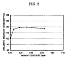
- the relation between the boron content and the relative emission intensity is shown in Fig.2 .
- the boron content of the comparative example 1 is not more than 0.0001 wt%, the boron content is increased when the BN powder is added in the examples 1 to 4, in such a way that 0.
- 063 wt% of the boron content is obtained when 0.1 wt% of the BN powder is added, 0.170 wt% of the boron content is obtained when 0.5 wt% of the BN powder is added, 0.310 wt% of the boron content is obtained when 1.0 wt% of the BN powder is added, and 0.640 wt% of the boron content is obtained when 2.0 wt% of the BN powder is added.
- the emission intensity is improved.
- the emission intensity is increased having a peak in the range from 0.15 wt% to 0.35 wt% of the boron content, and is increased by 19.6 % compared to that of the comparative example 1 without BN addition.
- the peak wavelength is liable to shift toward the longer wavelength side.
- the average particle size is approximately the same as that of the comparative example 1 without BN addition.
- the average particle size becomes 10.58 ⁇ m, and two times of the size is obtained, compared to the size of the comparative example 1 (5.851 ⁇ m) without BN addition. From this result, in the phosphor containing the boron in a certain range, it appears that the reaction is accelerated, and the emission intensity is improved.
- the phosphor sample is manufactured by adding fluorine calcium CaF 2 (3N) as an additive agent, in addition to each raw material of Ca 3 N 2 (2N), AlN(3N), Si 3 N 4 (3N), Eu 2 O 3 (3N) explained in the comparative example 1, and further by changing the crucible from the Si 3 N 4 crucible to the BN crucible.
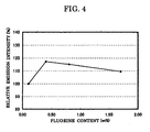
- the composition formula of each phosphor the analysis result of the fluorine concentration, the measurement result of the emission characteristics (peak wavelength, emission intensity, and chromaticity) and the powder characteristics (particle size and specific surface area BET) are shown in Fig.3 , and the relation between the fluorine content and the relative emission intensity (the relative intensity of the emission intensity of the comparative example 1 is defined as 100%) is shown in Fig.4 .
- the fluorine content is increased by adding CaF 2 powder.
- the fluorine content is increased when CaF 2 powder is added in the examples 5 to 7, respectively, wherein 0.40 wt% of the fluorine content is obtained when 0.025 mol of CaF 2 powder is added, 0.80 wt% of fluorine content is obtained when 0.050 mol of CaF 2 powder is added, and 1.70 wt% of fluorine content is obtained when 0.100 mol of CaF 2 powder is added.
- the emission intensity is improved.
- the emission intensity is gradually improved up to 0.40 wt% of the fluorine content, and is decreased when the fluorine content exceeds 0.40 wt%. Further, the emission intensity is improved having a peak at 0.40 wt% of the fluorine content, thereby showing 17.3% of improvement compared to case of the comparative example 1 without CaF 2 addition. Further, by containing the fluorine, the peak wavelength is liable to shift toward the longer wavelength side.
- the average particle size was the same as that of the comparative example 1 without BN addition. From this result, in the same way as the boron, in the phosphor containing the fluorine in a certain range also, it appears that the reaction is accelerated, and the emission intensity is improved.
- metal Ca with 99.5% of purity and 90 ppm content of the element Fe was heated in the nitrogen atmosphere at 700°C, then the metal thus heated was pulverized, and Ca 3 N 2 was thereby manufactured.
- the content of the element Fe of the Ca 3 N 2 thus manufactured was 60 ppm.
- the Ca 3 N 2 thus manufactured and other raw materials are weighed to obtain the ratio of 0.980/3 mol of Ca 3 N 2 , 1/3 mol of Si 3 N 4 , 1 mol of AlM, and 0.020/2 mol of Eu 2 O 3 , then mixed in the mortar and fired at 1600°C for 3 hours with pressure of 0.05 MPa in the nitrogen atmosphere, and a red phosphor CaAlSiN 3 :Eu was manufactured.
- the nitrogen is ventilated at 1.0L/min.
- the contents of the element Fe of the Ca 3 N 2 , Si 3 N 4 , AlN, and Eu 2 O 3 were 60 ppm, 20 ppm, 90 ppm, and 10 ppm, respectively.
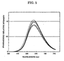
- Fig.5 shows the emission spectrum of the phosphor powders manufactured by the example 8 and the examples 9 to 10 as will be described later and the comparative examples 2 to 4, respectively, showing the emission wavelength taken on the abscissa axis, and the relative emission intensity taken on the ordinate axis.
- the emission intensity of the example 8 is standardized as 1, and the relative emission intensity of other example is obtained.
- the phosphor powder of the example 8 thus obtained was irradiated with monochromatic light of 460 nm wavelength, the phosphor powder emitted red light having the emission spectrum with a peak at 656 nm and a half value width of 50 nm or more.
- the content of the element Fe, which is an impurity of the phosphor of the example 8, obtained by chemical analysis was 100 ppm.
- Fig.6 shows the relative emission intensity to the concentration of impurity element Fe of the phosphor manufactured by the example 8, the examples 9 to 10 as will be described later, and the comparative examples 2 to 4, wherein the emission intensity of the example 8 is standardized as 1, and then the relative emission intensity of other example and comparative example is obtained.
- the table 1 shows the concentration of the impurity element Fe obtained by the chemical analysis of Ca 3 N 2 (2N), Si 3 N 4 (3N), AlN(3N), and Eu 2 O 3 (3N), which are raw materials of the phosphor manufactured in the example and the comparative example, the relative emission intensity of the phosphor manufactured by the example and the comparative example, and the content of the impurity Element Fe obtained by the chemical analysis.
- the relative emission intensity of other example and the comparative example is obtained by standardizing the emission intensity of the example 8 as 1.
- the red phosphor CaAlSiN 3 :Eu was manufactured under the same condition as that of the example 8, other than using Ca 3 N 2 raw material having lower content of the element Fe than that of the example 8.
- the contents of the element Fe of Ca 3 N 2 , Si 3 N 4 , AlN, and Eu 2 O 3 used in the raw materials were 27 ppm, 20 ppm, 90 ppm, and 10 ppm, respectively.
- the phosphor powder thus obtained was irradiated with the monochromatic light of 460 nm, as shown in a thick broken line of Fig.5 , the phosphor powder emitted red light having the emission spectrum with a peak at 656 nm and the half value width of 50 nm or more. Also, as shown in the table 1 and Fig.6 , the content of the impurity element Fe of the phosphor thus obtained by the chemical analysis was 80 ppm.
- the red phosphor CaAlSiN 3 :Eu was prepared under the same condition as that of the example 8, other than using Ca 3 N 2 raw material having 10 ppm more content of the element Fe than that of the example 8.
- the contents of the element Fe of the Ca 3 N 2 , Si 3 N 4 , AlN, Eu 2 O 3 were 70 ppm, 20 ppm, 90 ppm, and 10 ppm.
- the phosphor powder thus obtained was irradiated with the monochromatic light of 460 nm, as shown by a thick two-dot line in Fig.5 , the phosphor powder emitted red light having the emission spectrum with a peak at 656 nm and a half value width of 50 nm or more. Also, as shown in the table 1 and Fig.6 , the content of the impurity element Fe of the phosphor thus obtained by the chemical analysis was 120 ppm.
- the red phosphor CaAlSiN 3 :Eu was prepared under the same condition as that of the example 8, other than using Ca 3 N 2 raw material having 230 ppm content of the element Fe.
- the phosphor powder thus obtained was irradiated with the monochromatic light of 460 nm, as shown by a thin solid line of Fig.5 , the phosphor powder emitted red light having the emission spectrum with a peak at 656 nm and a half value width of 50 nm or more. Also, as shown in the table 1 and Fig. 6 , the content of the impurity element Fe of the phosphor obtained by the chemical analysis was 260 ppm.
- the red phosphor CaAlSiN 3 :Eu was prepared under the same condition as that of the example 8, other than using the commercially available Ca 3 N 2 raw material having 770 ppm content of the element Fe.
- the phosphor powder thus obtained was irradiated with the monochromatic light of 460 nm, as shown by the thin broken line of Fig.5 , the phosphor powder emitted red light having the emission spectrum with a peak at 656 nm and a half value width of 50 nm or more. Also, as shown in the table 1 and Fig.6 , the content of the impurity element Fe of the phosphor obtained by the chemical analysis was 400 ppm. (Comparative example 4).
- the red phosphor CaAlSiN 3 :Eu was prepared under the same condition of that of the example 8, other than using Ca 3 N 2 raw material having 1400 ppm content of the element Fe.
- the content of the element Fe of Si 3 N 4 , AlN, and Eu 2 O 3 , which were other raw materials were 20 ppm, 90 ppm, and 10 ppm, respectively.
- the phosphor powder thus obtained was irradiated with the monochromatic light of 460 nm, as shown by a thin one-dot chain line of Fig.5 , the phosphor powder emitted red light having the emission spectrum with a peak at 656 nm and half value width of 50 nm or more. Also, as shown in the table 1 and Fig.6 , the content of the impurity element Fe of the phosphor obtained by the chemical analysis was 600 ppm.
- the emission intensity is drastically decreased when the content of the element Fe exceeds 200 ppm, in the phosphor powder manufactured in the comparative examples 2 to 4. This is because the element Fe has a bad influence on the emission characteristics as a killer element to largely deteriorate the emission efficiency. Such an action is considered to be caused in such a way that when the content of the element Fe exceeds 200 ppm, energy transfer to the center of the light emission of the phosphor powder is significantly interfered, and as a result, the emission intensity is largely deteriorated.
- the concentration of the element Fe in the raw material is controlled to be 200 ppm or less.
- the concentration of the element Fe of the phosphor powder is suppressed to be 200 ppm or less.
- the energy transfer to the center of the light emission of the phosphor powder is not interfered, thereby preventing the deterioration of the emission intensity. This contributes to improving and stabilizing the emission efficiency of the phosphor.
Landscapes
- Chemical & Material Sciences (AREA)
- Inorganic Chemistry (AREA)
- Engineering & Computer Science (AREA)
- Materials Engineering (AREA)
- Organic Chemistry (AREA)
- Luminescent Compositions (AREA)
Applications Claiming Priority (3)
| Application Number | Priority Date | Filing Date | Title |
|---|---|---|---|
| JP2004248405A JP2006063214A (ja) | 2004-08-27 | 2004-08-27 | 蛍光体及びその製造方法並びに光源 |
| JP2005105126A JP2006282872A (ja) | 2005-03-31 | 2005-03-31 | 窒化物蛍光体または酸窒化物蛍光体、及びその製造方法、並びに当該蛍光体を用いた発光装置 |
| EP05018712A EP1630219B2 (fr) | 2004-08-27 | 2005-08-29 | Luminophore, procédé de fabrication d'un luminophore et source de lumière l'utilisant |
Related Parent Applications (2)
| Application Number | Title | Priority Date | Filing Date |
|---|---|---|---|
| EP05018712.9 Division | 2005-08-29 | ||
| EP05018712A Division EP1630219B2 (fr) | 2004-08-27 | 2005-08-29 | Luminophore, procédé de fabrication d'un luminophore et source de lumière l'utilisant |
Publications (2)
| Publication Number | Publication Date |
|---|---|
| EP2022836A1 true EP2022836A1 (fr) | 2009-02-11 |
| EP2022836B1 EP2022836B1 (fr) | 2011-10-19 |
Family
ID=35169922
Family Applications (2)
| Application Number | Title | Priority Date | Filing Date |
|---|---|---|---|
| EP05018712A Expired - Lifetime EP1630219B2 (fr) | 2004-08-27 | 2005-08-29 | Luminophore, procédé de fabrication d'un luminophore et source de lumière l'utilisant |
| EP08018901A Expired - Lifetime EP2022836B1 (fr) | 2004-08-27 | 2005-08-29 | Phosphore et son procédé de fabrication, et source lumineuse l'utilisant |
Family Applications Before (1)
| Application Number | Title | Priority Date | Filing Date |
|---|---|---|---|
| EP05018712A Expired - Lifetime EP1630219B2 (fr) | 2004-08-27 | 2005-08-29 | Luminophore, procédé de fabrication d'un luminophore et source de lumière l'utilisant |
Country Status (3)
| Country | Link |
|---|---|
| US (3) | US7476338B2 (fr) |
| EP (2) | EP1630219B2 (fr) |
| DE (1) | DE602005015397D1 (fr) |
Cited By (2)
| Publication number | Priority date | Publication date | Assignee | Title |
|---|---|---|---|---|
| CN104650861A (zh) * | 2015-02-10 | 2015-05-27 | 江门市远大发光材料有限公司 | 一种简易制备碱土氮化物红色荧光粉的方法 |
| CN108822835A (zh) * | 2013-10-08 | 2018-11-16 | 欧司朗光电半导体有限公司 | 发光材料、用于制造发光材料的方法和发光材料的应用 |
Families Citing this family (54)
| Publication number | Priority date | Publication date | Assignee | Title |
|---|---|---|---|---|
| KR100961322B1 (ko) * | 2002-03-22 | 2010-06-04 | 니치아 카가쿠 고교 가부시키가이샤 | 질화물 형광체와 그 제조 방법 및 발광 장치 |
| JP3837588B2 (ja) | 2003-11-26 | 2006-10-25 | 独立行政法人物質・材料研究機構 | 蛍光体と蛍光体を用いた発光器具 |
| JP4568894B2 (ja) | 2003-11-28 | 2010-10-27 | Dowaエレクトロニクス株式会社 | 複合導体および超電導機器システム |
| JP3931239B2 (ja) * | 2004-02-18 | 2007-06-13 | 独立行政法人物質・材料研究機構 | 発光素子及び照明器具 |
| JP4511849B2 (ja) * | 2004-02-27 | 2010-07-28 | Dowaエレクトロニクス株式会社 | 蛍光体およびその製造方法、光源、並びにled |
| JP4524468B2 (ja) | 2004-05-14 | 2010-08-18 | Dowaエレクトロニクス株式会社 | 蛍光体とその製造方法および当該蛍光体を用いた光源並びにled |
| JP4491585B2 (ja) * | 2004-05-28 | 2010-06-30 | Dowaエレクトロニクス株式会社 | 金属ペーストの製造方法 |
| JP4414821B2 (ja) * | 2004-06-25 | 2010-02-10 | Dowaエレクトロニクス株式会社 | 蛍光体並びに光源およびled |
| JP4511885B2 (ja) * | 2004-07-09 | 2010-07-28 | Dowaエレクトロニクス株式会社 | 蛍光体及びled並びに光源 |
| US7476337B2 (en) * | 2004-07-28 | 2009-01-13 | Dowa Electronics Materials Co., Ltd. | Phosphor and manufacturing method for the same, and light source |
| JP4933739B2 (ja) * | 2004-08-02 | 2012-05-16 | Dowaホールディングス株式会社 | 電子線励起用の蛍光体および蛍光体膜、並びにそれらを用いたカラー表示装置 |
| US7138756B2 (en) | 2004-08-02 | 2006-11-21 | Dowa Mining Co., Ltd. | Phosphor for electron beam excitation and color display device using the same |
| JP4524470B2 (ja) | 2004-08-20 | 2010-08-18 | Dowaエレクトロニクス株式会社 | 蛍光体およびその製造方法、並びに当該蛍光体を用いた光源 |
| JP4543250B2 (ja) * | 2004-08-27 | 2010-09-15 | Dowaエレクトロニクス株式会社 | 蛍光体混合物および発光装置 |
| US7476338B2 (en) | 2004-08-27 | 2009-01-13 | Dowa Electronics Materials Co., Ltd. | Phosphor and manufacturing method for the same, and light source |
| JP4543253B2 (ja) * | 2004-10-28 | 2010-09-15 | Dowaエレクトロニクス株式会社 | 蛍光体混合物および発光装置 |
| US7854859B2 (en) * | 2004-12-28 | 2010-12-21 | Nichia Corporation | Nitride phosphor, method for producing this nitride phosphor, and light emitting device that uses this nitride phosphor |
| JP4892193B2 (ja) * | 2005-03-01 | 2012-03-07 | Dowaホールディングス株式会社 | 蛍光体混合物および発光装置 |
| US7524437B2 (en) * | 2005-03-04 | 2009-04-28 | Dowa Electronics Materials Co., Ltd. | Phosphor and manufacturing method of the same, and light emitting device using the phosphor |
| CN101138278A (zh) * | 2005-03-09 | 2008-03-05 | 皇家飞利浦电子股份有限公司 | 包括辐射源和荧光材料的照明系统 |
| WO2006098450A1 (fr) | 2005-03-18 | 2006-09-21 | Mitsubishi Chemical Corporation | Dispositif luminescent, dispositif luminescent blanc, dispositif d’éclairage et affichage d’image |
| US7445730B2 (en) * | 2005-03-31 | 2008-11-04 | Dowa Electronics Materials Co., Ltd. | Phosphor and manufacturing method of the same, and light emitting device using the phosphor |
| US7443094B2 (en) * | 2005-03-31 | 2008-10-28 | Dowa Electronics Materials Co., Ltd. | Phosphor and manufacturing method of the same, and light emitting device using the phosphor |
| JP4975269B2 (ja) * | 2005-04-28 | 2012-07-11 | Dowaホールディングス株式会社 | 蛍光体およびその製造方法、並びに当該蛍光体を用いた発光装置 |
| US8206611B2 (en) | 2005-05-24 | 2012-06-26 | Mitsubishi Chemical Corporation | Phosphor and use thereof |
| US7859182B2 (en) | 2005-08-31 | 2010-12-28 | Lumination Llc | Warm white LED-based lamp incoporating divalent EU-activated silicate yellow emitting phosphor |
| US7262439B2 (en) * | 2005-11-22 | 2007-08-28 | Lumination Llc | Charge compensated nitride phosphors for use in lighting applications |
| EP1964904B1 (fr) * | 2005-12-08 | 2011-04-13 | National Institute for Materials Science | Phosphore, procede de production correspondant et dispositif luminescent |
| WO2008096300A1 (fr) | 2007-02-06 | 2008-08-14 | Philips Intellectual Property & Standards Gmbh | Matières électroluminescentes rouges |
| DE102007018099A1 (de) | 2007-04-17 | 2008-10-23 | Osram Gesellschaft mit beschränkter Haftung | Rot emittierender Leuchtstoff und Lichtquelle mit derartigem Leuchtstoff |
| JP5578597B2 (ja) | 2007-09-03 | 2014-08-27 | 独立行政法人物質・材料研究機構 | 蛍光体及びその製造方法、並びにそれを用いた発光装置 |
| KR100932978B1 (ko) * | 2007-11-28 | 2009-12-21 | 삼성에스디아이 주식회사 | 백색 형광체, 이를 이용하는 발광 장치, 및 이 발광 장치를백 라이트 유닛으로 사용하는 액정 표시 장치 |
| KR100898288B1 (ko) * | 2008-01-09 | 2009-05-18 | 삼성에스디아이 주식회사 | 백색 형광체, 이를 이용하는 발광 장치, 및 이 발광 장치를백 라이트 유닛으로 사용하는 액정 표시 장치 |
| US8567973B2 (en) | 2008-03-07 | 2013-10-29 | Intematix Corporation | Multiple-chip excitation systems for white light emitting diodes (LEDs) |
| US8740400B2 (en) | 2008-03-07 | 2014-06-03 | Intematix Corporation | White light illumination system with narrow band green phosphor and multiple-wavelength excitation |
| US20090283721A1 (en) * | 2008-05-19 | 2009-11-19 | Intematix Corporation | Nitride-based red phosphors |
| US8274215B2 (en) * | 2008-12-15 | 2012-09-25 | Intematix Corporation | Nitride-based, red-emitting phosphors |
| JP5641384B2 (ja) * | 2008-11-28 | 2014-12-17 | 独立行政法人物質・材料研究機構 | 表示装置用照明装置及び表示装置 |
| CN101921592B (zh) * | 2010-09-09 | 2012-12-26 | 江苏博睿光电有限公司 | 一种白光led红色荧光粉及其制造方法 |
| TW201213506A (en) * | 2010-09-30 | 2012-04-01 | Chi Mei Corp | Phosphor and luminous device |
| US8663502B2 (en) | 2011-12-30 | 2014-03-04 | Intematix Corporation | Red-emitting nitride-based phosphors |
| EP2797838A4 (fr) | 2011-12-30 | 2015-07-01 | Intematix Corp | Substances luminescentes à base de nitrures comprenant des cations interstitiels pour le bilan ionique |
| US8597545B1 (en) | 2012-07-18 | 2013-12-03 | Intematix Corporation | Red-emitting nitride-based calcium-stabilized phosphors |
| US8851950B2 (en) * | 2012-09-26 | 2014-10-07 | General Electric Company | Recyclability of fluorescent lamp phosphors |
| DE102013100429B4 (de) | 2013-01-16 | 2023-12-07 | Osram Gmbh | Verfahren zur Herstellung eines pulverförmigen Precursormaterials und Verwendung eines mit dem Verfahren hergestellten pulverförmigen Precursormaterials |
| EP2966051B1 (fr) * | 2014-07-10 | 2023-11-01 | Centre National De La Recherche Scientifique | Procédé de fabrication d'un élément en céramique à base de sulfure pour les applications IR-optiques |
| US9200199B1 (en) | 2014-08-28 | 2015-12-01 | Lightscape Materials, Inc. | Inorganic red phosphor and lighting devices comprising same |
| US9200198B1 (en) | 2014-08-28 | 2015-12-01 | Lightscape Materials, Inc. | Inorganic phosphor and light emitting devices comprising same |
| US9315725B2 (en) | 2014-08-28 | 2016-04-19 | Lightscape Materials, Inc. | Method of making EU2+ activated inorganic red phosphor |
| EP3492556A4 (fr) | 2016-07-27 | 2019-10-02 | Mitsubishi Chemical Corporation | Phosphore fritté, dispositif électroluminescent, dispositif d'éclairage et lampe témoin de véhicule |
| US10590342B2 (en) | 2016-08-25 | 2020-03-17 | Nichia Corporation | Nitride fluorescent material, method of producing nitride fluorescent material and light emitting device |
| KR102541392B1 (ko) | 2018-06-28 | 2023-06-13 | 애플 인크. | 저 레이턴시 비디오 인코딩 및 송신을 위한 레이트 제어 |
| WO2020006291A1 (fr) | 2018-06-28 | 2020-01-02 | Apple Inc. | Codage et transmission vidéo fondés sur la priorité |
| US20220154070A1 (en) * | 2019-04-09 | 2022-05-19 | Denka Company Limited | Nitride fluorescent material and light emission device |
Citations (10)
| Publication number | Priority date | Publication date | Assignee | Title |
|---|---|---|---|---|
| JP2001214162A (ja) | 2000-02-02 | 2001-08-07 | Japan Science & Technology Corp | オキシ窒化物ガラスを母体材料とした蛍光体 |
| JP2002363554A (ja) * | 2001-06-07 | 2002-12-18 | National Institute For Materials Science | 希土類元素を付活させた酸窒化物蛍光体 |
| EP1278250A2 (fr) * | 2001-07-16 | 2003-01-22 | Patent-Treuhand-Gesellschaft für elektrische Glühlampen mbH | Unité d'éclairage comportant au moins une diode électroluminescente comme source de lumière |
| EP1296376A2 (fr) * | 2001-09-25 | 2003-03-26 | Patent-Treuhand-Gesellschaft für elektrische Glühlampen mbH | Unité d'éclairage comportant au moins une diode électroluminescente comme source de lumière |
| EP1296383A2 (fr) * | 2001-09-20 | 2003-03-26 | Patent-Treuhand-Gesellschaft für elektrische Glühlampen mbH | Unité de rayonnement avec au moins une diode LED |
| JP2003515655A (ja) | 1999-11-30 | 2003-05-07 | オスラム オプト セミコンダクターズ ゲゼルシャフト ミット ベシュレンクテル ハフツング | 黄色から赤色を放射する蛍光体を用いる光源 |
| JP2003277746A (ja) | 2002-03-22 | 2003-10-02 | Nichia Chem Ind Ltd | 窒化物蛍光体及びその製造方法 |
| JP2003336059A (ja) | 2002-05-23 | 2003-11-28 | National Institute For Materials Science | サイアロン系蛍光体 |
| JP2004055536A (ja) | 2002-05-29 | 2004-02-19 | Toyota Central Res & Dev Lab Inc | 色素増感型太陽電池 |
| JP2004067837A (ja) * | 2002-08-06 | 2004-03-04 | Toyota Central Res & Dev Lab Inc | α−サイアロン蛍光体 |
Family Cites Families (74)
| Publication number | Priority date | Publication date | Assignee | Title |
|---|---|---|---|---|
| US18985A (en) * | 1857-12-29 | Island | ||
| US2121275A (en) * | 1935-05-03 | 1938-06-21 | Zober Benjamin | Colloid mill |
| US3527595A (en) * | 1963-10-01 | 1970-09-08 | Arthur Adler | Homogeneous metal-containing solid mixtures |
| US3697301A (en) * | 1971-04-05 | 1972-10-10 | Gte Sylvania Inc | Process of forming cathode ray tube screens to utilize the luminous efficiency of the phosphor material |
| JPS585222U (ja) * | 1981-07-02 | 1983-01-13 | 三菱電機株式会社 | 超電導機器の電流中継装置 |
| US4576736A (en) * | 1984-03-19 | 1986-03-18 | International Business Machines Corporation | Method of predicting and controlling the viscosity of conductive pastes |
| NL8501599A (nl) * | 1985-06-04 | 1987-01-02 | Philips Nv | Luminescerend scherm en lagedrukkwikdampontladingslamp voorzien van een dergelijk scherm. |
| DE4017553C1 (fr) | 1990-05-31 | 1991-09-19 | Kernforschungszentrum Karlsruhe Gmbh, 7500 Karlsruhe, De | |
| JPH0515655A (ja) | 1991-07-10 | 1993-01-26 | Ace Denken:Kk | 遊技機用のicカード |
| JP3142934B2 (ja) | 1992-01-20 | 2001-03-07 | 株式会社東芝 | 超電導電流リードの接続構造体 |
| US5290638A (en) * | 1992-07-24 | 1994-03-01 | Massachusetts Institute Of Technology | Superconducting joint with niobium-tin |
| US5447291A (en) * | 1993-10-08 | 1995-09-05 | The Ohio State University | Processes for fabricating structural ceramic bodies and structural ceramic-bearing composite bodies |
| JP3425465B2 (ja) * | 1994-03-03 | 2003-07-14 | 化成オプトニクス株式会社 | 緑色発光蛍光体及びそれを用いた陰極線管 |
| AU6665598A (en) * | 1997-02-24 | 1998-09-09 | Superior Micropowders Llc | Sulfur-containing phosphor powders, methods for making phosphor powders and devices incorporating same |
| JPH11144938A (ja) | 1997-11-10 | 1999-05-28 | Mitsubishi Electric Corp | 電流リード装置および冷凍機冷却型超電導マグネット |
| JPH11277527A (ja) | 1998-03-30 | 1999-10-12 | Toshiba Chem Corp | 混練装置 |
| JP2000073053A (ja) | 1998-09-01 | 2000-03-07 | Hitachi Ltd | 蛍光体及びこの蛍光体を用いた陰極線管 |
| JP3998353B2 (ja) | 1998-11-20 | 2007-10-24 | 大日本塗料株式会社 | コロイドミル |
| KR100342044B1 (ko) * | 1999-04-14 | 2002-06-27 | 김순택 | 녹색발광 형광체 조성물 및 이를 이용하여 제조된 음극선관 |
| US7366687B2 (en) * | 2000-03-30 | 2008-04-29 | Sony Corporation | Donation processing system |
| DE10036940A1 (de) | 2000-07-28 | 2002-02-07 | Patent Treuhand Ges Fuer Elektrische Gluehlampen Mbh | Lumineszenz-Konversions-LED |
| JP2002076434A (ja) * | 2000-08-28 | 2002-03-15 | Toyoda Gosei Co Ltd | 発光装置 |
| US7138581B2 (en) * | 2001-01-16 | 2006-11-21 | Nippon Steel Corporation | Low resistance conductor, processes of production thereof, and electrical members using same |
| US6632379B2 (en) * | 2001-06-07 | 2003-10-14 | National Institute For Materials Science | Oxynitride phosphor activated by a rare earth element, and sialon type phosphor |
| JP2003013059A (ja) | 2001-06-27 | 2003-01-15 | Hitachi Ltd | カラー陰極線管及びそれに用いる赤色蛍光体 |
| JP3643868B2 (ja) | 2001-09-21 | 2005-04-27 | 独立行政法人物質・材料研究機構 | セリウムイオンの付活したランタン窒化ケイ素蛍光体 |
| JP2005509081A (ja) * | 2001-11-14 | 2005-04-07 | サーノフ・コーポレーション | 光励起発光型赤色蛍光体 |
| JP2003238953A (ja) * | 2002-02-13 | 2003-08-27 | Tdk Corp | 蛍光体およびelパネル |
| JP4656816B2 (ja) | 2002-06-27 | 2011-03-23 | 日亜化学工業株式会社 | 発光装置 |
| JP4356915B2 (ja) | 2002-07-22 | 2009-11-04 | 東京エレクトロン株式会社 | プローブ装置及びプローブカードのチャンネル情報作成プログラム並びにプローブカードのチャンネル情報作成装置 |
| US6943426B2 (en) * | 2002-08-14 | 2005-09-13 | Advanced Analogic Technologies, Inc. | Complementary analog bipolar transistors with trench-constrained isolation diffusion |
| EP1413618A1 (fr) * | 2002-09-24 | 2004-04-28 | Osram Opto Semiconductors GmbH | Matière luminescente, en particulier pour application dans des diodes électroluminescentes |
| MY149573A (en) | 2002-10-16 | 2013-09-13 | Nichia Corp | Oxynitride phosphor and production process thereof, and light-emitting device using oxynitride phosphor |
| JP4415548B2 (ja) | 2002-10-16 | 2010-02-17 | 日亜化学工業株式会社 | オキシ窒化物蛍光体を用いた発光装置 |
| JP2004145718A (ja) | 2002-10-25 | 2004-05-20 | Ishikawajima Harima Heavy Ind Co Ltd | 構造解析モデル生成装置及び方法 |
| JP4072632B2 (ja) * | 2002-11-29 | 2008-04-09 | 豊田合成株式会社 | 発光装置及び発光方法 |
| DE60312733T2 (de) | 2002-12-13 | 2007-12-06 | Philips Intellectual Property & Standards Gmbh | Beleuchtungsvorrichtung mit strahlungsquelle und fluoreszenzmaterial |
| US7074346B2 (en) * | 2003-02-06 | 2006-07-11 | Ube Industries, Ltd. | Sialon-based oxynitride phosphor, process for its production, and use thereof |
| JP2004248405A (ja) | 2003-02-13 | 2004-09-02 | Fuji Heavy Ind Ltd | 車両のバッテリ管理装置 |
| JP4244653B2 (ja) | 2003-02-17 | 2009-03-25 | 日亜化学工業株式会社 | シリコンナイトライド系蛍光体及びそれを用いた発光装置 |
| WO2004081140A1 (fr) * | 2003-03-13 | 2004-09-23 | Nichia Corporation | Film luminescent, dispositif luminescent, procede de fabrication d'un film luminescent, et procede de fabrication d'un dispositif luminescent |
| US7462983B2 (en) * | 2003-06-27 | 2008-12-09 | Avago Technologies Ecbu Ip (Singapore) Pte. Ltd. | White light emitting device |
| JP4834827B2 (ja) | 2003-10-03 | 2011-12-14 | 独立行政法人物質・材料研究機構 | 酸窒化物蛍光体 |
| TWI359187B (en) * | 2003-11-19 | 2012-03-01 | Panasonic Corp | Method for preparing nitridosilicate-based compoun |
| JP3837588B2 (ja) | 2003-11-26 | 2006-10-25 | 独立行政法人物質・材料研究機構 | 蛍光体と蛍光体を用いた発光器具 |
| JP4568894B2 (ja) * | 2003-11-28 | 2010-10-27 | Dowaエレクトロニクス株式会社 | 複合導体および超電導機器システム |
| JP2005192691A (ja) | 2004-01-05 | 2005-07-21 | Symbolic Atorii:Kk | 側地袋着脱式寝具 |
| JP4511849B2 (ja) * | 2004-02-27 | 2010-07-28 | Dowaエレクトロニクス株式会社 | 蛍光体およびその製造方法、光源、並びにled |
| JP5016187B2 (ja) | 2004-07-14 | 2012-09-05 | Dowaエレクトロニクス株式会社 | 窒化物蛍光体、窒化物蛍光体の製造方法、並びに上記窒化物蛍光体を用いた光源及びled |
| KR101157313B1 (ko) * | 2004-04-27 | 2012-06-18 | 파나소닉 주식회사 | 형광체 조성물과 그 제조방법, 및 그 형광체 조성물을 이용한 발광 장치 |
| JP4524468B2 (ja) * | 2004-05-14 | 2010-08-18 | Dowaエレクトロニクス株式会社 | 蛍光体とその製造方法および当該蛍光体を用いた光源並びにled |
| JP4491585B2 (ja) * | 2004-05-28 | 2010-06-30 | Dowaエレクトロニクス株式会社 | 金属ペーストの製造方法 |
| JP4524469B2 (ja) | 2004-06-03 | 2010-08-18 | Dowaエレクトロニクス株式会社 | 蛍光体粒子およびその製造方法並びにプラズマディスプレイパネル、照明装置およびled |
| JP4414821B2 (ja) * | 2004-06-25 | 2010-02-10 | Dowaエレクトロニクス株式会社 | 蛍光体並びに光源およびled |
| JP4511885B2 (ja) * | 2004-07-09 | 2010-07-28 | Dowaエレクトロニクス株式会社 | 蛍光体及びled並びに光源 |
| US7476337B2 (en) * | 2004-07-28 | 2009-01-13 | Dowa Electronics Materials Co., Ltd. | Phosphor and manufacturing method for the same, and light source |
| JP4933739B2 (ja) * | 2004-08-02 | 2012-05-16 | Dowaホールディングス株式会社 | 電子線励起用の蛍光体および蛍光体膜、並びにそれらを用いたカラー表示装置 |
| US7138756B2 (en) * | 2004-08-02 | 2006-11-21 | Dowa Mining Co., Ltd. | Phosphor for electron beam excitation and color display device using the same |
| JP4524470B2 (ja) * | 2004-08-20 | 2010-08-18 | Dowaエレクトロニクス株式会社 | 蛍光体およびその製造方法、並びに当該蛍光体を用いた光源 |
| US7476338B2 (en) | 2004-08-27 | 2009-01-13 | Dowa Electronics Materials Co., Ltd. | Phosphor and manufacturing method for the same, and light source |
| JP2006282872A (ja) | 2005-03-31 | 2006-10-19 | Dowa Mining Co Ltd | 窒化物蛍光体または酸窒化物蛍光体、及びその製造方法、並びに当該蛍光体を用いた発光装置 |
| JP4543250B2 (ja) * | 2004-08-27 | 2010-09-15 | Dowaエレクトロニクス株式会社 | 蛍光体混合物および発光装置 |
| JP2006063214A (ja) | 2004-08-27 | 2006-03-09 | Dowa Mining Co Ltd | 蛍光体及びその製造方法並びに光源 |
| JP4729278B2 (ja) | 2004-08-30 | 2011-07-20 | Dowaエレクトロニクス株式会社 | 蛍光体及び発光装置 |
| JP4543251B2 (ja) | 2004-08-31 | 2010-09-15 | Dowaエレクトロニクス株式会社 | 蛍光体及び光源 |
| JP4543253B2 (ja) * | 2004-10-28 | 2010-09-15 | Dowaエレクトロニクス株式会社 | 蛍光体混合物および発光装置 |
| JP4798335B2 (ja) | 2004-12-20 | 2011-10-19 | Dowaエレクトロニクス株式会社 | 蛍光体および蛍光体を用いた光源 |
| JP4892193B2 (ja) * | 2005-03-01 | 2012-03-07 | Dowaホールディングス株式会社 | 蛍光体混合物および発光装置 |
| EP1867697B1 (fr) | 2005-03-04 | 2014-05-14 | Mitsubishi Chemical Corporation | Substance fluorescente et procede de production de celle-ci, et dispositif d'emission de lumiere utilisant ladite substance fluorescente |
| US7524437B2 (en) * | 2005-03-04 | 2009-04-28 | Dowa Electronics Materials Co., Ltd. | Phosphor and manufacturing method of the same, and light emitting device using the phosphor |
| US7443094B2 (en) * | 2005-03-31 | 2008-10-28 | Dowa Electronics Materials Co., Ltd. | Phosphor and manufacturing method of the same, and light emitting device using the phosphor |
| US7445730B2 (en) * | 2005-03-31 | 2008-11-04 | Dowa Electronics Materials Co., Ltd. | Phosphor and manufacturing method of the same, and light emitting device using the phosphor |
| JP5036975B2 (ja) | 2005-03-31 | 2012-09-26 | Dowaホールディングス株式会社 | 窒素を含有する蛍光体およびその製造方法、並びに発光装置 |
| JP4975269B2 (ja) * | 2005-04-28 | 2012-07-11 | Dowaホールディングス株式会社 | 蛍光体およびその製造方法、並びに当該蛍光体を用いた発光装置 |
-
2005
- 2005-08-26 US US11/211,751 patent/US7476338B2/en active Active
- 2005-08-29 EP EP05018712A patent/EP1630219B2/fr not_active Expired - Lifetime
- 2005-08-29 DE DE602005015397T patent/DE602005015397D1/de not_active Expired - Lifetime
- 2005-08-29 EP EP08018901A patent/EP2022836B1/fr not_active Expired - Lifetime
-
2008
- 2008-11-28 US US12/292,889 patent/US7803286B2/en not_active Expired - Lifetime
-
2010
- 2010-06-18 US US12/801,658 patent/US8308981B2/en not_active Expired - Lifetime
Patent Citations (11)
| Publication number | Priority date | Publication date | Assignee | Title |
|---|---|---|---|---|
| JP2003515655A (ja) | 1999-11-30 | 2003-05-07 | オスラム オプト セミコンダクターズ ゲゼルシャフト ミット ベシュレンクテル ハフツング | 黄色から赤色を放射する蛍光体を用いる光源 |
| JP2001214162A (ja) | 2000-02-02 | 2001-08-07 | Japan Science & Technology Corp | オキシ窒化物ガラスを母体材料とした蛍光体 |
| JP2002363554A (ja) * | 2001-06-07 | 2002-12-18 | National Institute For Materials Science | 希土類元素を付活させた酸窒化物蛍光体 |
| EP1278250A2 (fr) * | 2001-07-16 | 2003-01-22 | Patent-Treuhand-Gesellschaft für elektrische Glühlampen mbH | Unité d'éclairage comportant au moins une diode électroluminescente comme source de lumière |
| JP2003124527A (ja) | 2001-07-16 | 2003-04-25 | Patent Treuhand Ges Elektr Gluehlamp Mbh | 光源として少なくとも1つのledを備えた照明ユニット |
| EP1296383A2 (fr) * | 2001-09-20 | 2003-03-26 | Patent-Treuhand-Gesellschaft für elektrische Glühlampen mbH | Unité de rayonnement avec au moins une diode LED |
| EP1296376A2 (fr) * | 2001-09-25 | 2003-03-26 | Patent-Treuhand-Gesellschaft für elektrische Glühlampen mbH | Unité d'éclairage comportant au moins une diode électroluminescente comme source de lumière |
| JP2003277746A (ja) | 2002-03-22 | 2003-10-02 | Nichia Chem Ind Ltd | 窒化物蛍光体及びその製造方法 |
| JP2003336059A (ja) | 2002-05-23 | 2003-11-28 | National Institute For Materials Science | サイアロン系蛍光体 |
| JP2004055536A (ja) | 2002-05-29 | 2004-02-19 | Toyota Central Res & Dev Lab Inc | 色素増感型太陽電池 |
| JP2004067837A (ja) * | 2002-08-06 | 2004-03-04 | Toyota Central Res & Dev Lab Inc | α−サイアロン蛍光体 |
Cited By (5)
| Publication number | Priority date | Publication date | Assignee | Title |
|---|---|---|---|---|
| CN108822835A (zh) * | 2013-10-08 | 2018-11-16 | 欧司朗光电半导体有限公司 | 发光材料、用于制造发光材料的方法和发光材料的应用 |
| US11292965B2 (en) | 2013-10-08 | 2022-04-05 | Osram Opto Semiconductors Gmbh | Phosphor, method for producing a phosphor and use of a phosphor |
| CN108822835B (zh) * | 2013-10-08 | 2022-07-29 | 欧司朗光电半导体有限公司 | 发光材料、用于制造发光材料的方法和发光材料的应用 |
| CN104650861A (zh) * | 2015-02-10 | 2015-05-27 | 江门市远大发光材料有限公司 | 一种简易制备碱土氮化物红色荧光粉的方法 |
| CN104650861B (zh) * | 2015-02-10 | 2017-05-10 | 江门市远大发光材料有限公司 | 一种简易制备碱土氮化物红色荧光粉的方法 |
Also Published As
| Publication number | Publication date |
|---|---|
| US7803286B2 (en) | 2010-09-28 |
| US20090109652A1 (en) | 2009-04-30 |
| EP2022836B1 (fr) | 2011-10-19 |
| US20100258766A1 (en) | 2010-10-14 |
| DE602005015397D1 (de) | 2009-08-27 |
| US8308981B2 (en) | 2012-11-13 |
| EP1630219A3 (fr) | 2007-04-25 |
| EP1630219B2 (fr) | 2012-08-01 |
| EP1630219A2 (fr) | 2006-03-01 |
| EP1630219B1 (fr) | 2009-07-15 |
| US7476338B2 (en) | 2009-01-13 |
| US20060065878A1 (en) | 2006-03-30 |
Similar Documents
| Publication | Publication Date | Title |
|---|---|---|
| EP2022836B1 (fr) | Phosphore et son procédé de fabrication, et source lumineuse l'utilisant | |
| US8048338B2 (en) | Phosphor, phosphor sheet, and manufacturing method therefore, and light emission device using the phosphor | |
| US7476336B2 (en) | Phosphor and manufacturing method for the same, and light emitting device using the phosphor | |
| EP1788063B1 (fr) | Phosphore et procédé pour sa fabrication, et source lumineuse | |
| US7445730B2 (en) | Phosphor and manufacturing method of the same, and light emitting device using the phosphor | |
| US7476335B2 (en) | Phosphor and manufacturing method therefore, and light source using the phosphor | |
| JP5245411B2 (ja) | 蛍光体およびその製造方法、並びに該蛍光体を用いた発光装置 | |
| US7443094B2 (en) | Phosphor and manufacturing method of the same, and light emitting device using the phosphor | |
| EP2067840B1 (fr) | Substance fluorescente, feuilles fluorescentes, procédé de fabrication de la substance fluorescente, dispositifs d'émission de lumière réalisés à l'aide de la substance | |
| EP2360227A1 (fr) | Luminophore et sa méthode de fabrication, méthode pour changer la longueur d'onde d'émission du luminophore et LED | |
| EP2075312B1 (fr) | Procédé de fabrication d'un luminophore à base de nitrure ou oxynitrure | |
| EP1783192B1 (fr) | Phosphore et appareil émetteur de lumière l'utilisant |
Legal Events
| Date | Code | Title | Description |
|---|---|---|---|
| PUAI | Public reference made under article 153(3) epc to a published international application that has entered the european phase |
Free format text: ORIGINAL CODE: 0009012 |
|
| AC | Divisional application: reference to earlier application |
Ref document number: 1630219 Country of ref document: EP Kind code of ref document: P |
|
| AK | Designated contracting states |
Kind code of ref document: A1 Designated state(s): DE FR GB |
|
| RTI1 | Title (correction) |
Free format text: PHOSPHOR AND MANUFACTURING MEHOD FOR THE SAME, AND LIGHT SOURCE USING THE SAME |
|
| RIN1 | Information on inventor provided before grant (corrected) |
Inventor name: IKUTA, TETSUYA Inventor name: YAMASHITA, SHUJI Inventor name: NAGATOMI, AKIRA Inventor name: SAKANE, KENJI Inventor name: GOTH, MASAHIRO |
|
| 17P | Request for examination filed |
Effective date: 20090528 |
|
| 17Q | First examination report despatched |
Effective date: 20090701 |
|
| AKX | Designation fees paid |
Designated state(s): DE FR GB |
|
| GRAP | Despatch of communication of intention to grant a patent |
Free format text: ORIGINAL CODE: EPIDOSNIGR1 |
|
| GRAS | Grant fee paid |
Free format text: ORIGINAL CODE: EPIDOSNIGR3 |
|
| GRAA | (expected) grant |
Free format text: ORIGINAL CODE: 0009210 |
|
| AC | Divisional application: reference to earlier application |
Ref document number: 1630219 Country of ref document: EP Kind code of ref document: P |
|
| AK | Designated contracting states |
Kind code of ref document: B1 Designated state(s): DE FR GB |
|
| REG | Reference to a national code |
Ref country code: GB Ref legal event code: FG4D |
|
| REG | Reference to a national code |
Ref country code: DE Ref legal event code: R096 Ref document number: 602005030775 Country of ref document: DE Effective date: 20111222 |
|
| PLBE | No opposition filed within time limit |
Free format text: ORIGINAL CODE: 0009261 |
|
| STAA | Information on the status of an ep patent application or granted ep patent |
Free format text: STATUS: NO OPPOSITION FILED WITHIN TIME LIMIT |
|
| 26N | No opposition filed |
Effective date: 20120720 |
|
| REG | Reference to a national code |
Ref country code: DE Ref legal event code: R097 Ref document number: 602005030775 Country of ref document: DE Effective date: 20120720 |
|
| REG | Reference to a national code |
Ref country code: FR Ref legal event code: PLFP Year of fee payment: 11 |
|
| REG | Reference to a national code |
Ref country code: DE Ref legal event code: R082 Ref document number: 602005030775 Country of ref document: DE Representative=s name: GRUENECKER PATENT- UND RECHTSANWAELTE PARTG MB, DE Ref country code: DE Ref legal event code: R081 Ref document number: 602005030775 Country of ref document: DE Owner name: CITIZEN ELECTRONICS CO., LTD., FUJIYOSHIDA-SHI, JP Free format text: FORMER OWNER: DOWA ELECTRONICS MATERIALS CO.,, NICHIA CORP., , JP Ref country code: DE Ref legal event code: R081 Ref document number: 602005030775 Country of ref document: DE Owner name: NICHIA CORP., ANAN-SHI, JP Free format text: FORMER OWNER: DOWA ELECTRONICS MATERIALS CO.,, NICHIA CORP., , JP Ref country code: DE Ref legal event code: R081 Ref document number: 602005030775 Country of ref document: DE Owner name: CITIZEN ELECTRONICS CO., LTD., FUJIYOSHIDA-SHI, JP Free format text: FORMER OWNERS: DOWA ELECTRONICS MATERIALS CO., LTD., TOKYO, JP; NICHIA CORP., ANAN-SHI, TOKUSHIMA, JP Ref country code: DE Ref legal event code: R081 Ref document number: 602005030775 Country of ref document: DE Owner name: NICHIA CORP., ANAN-SHI, JP Free format text: FORMER OWNERS: DOWA ELECTRONICS MATERIALS CO., LTD., TOKYO, JP; NICHIA CORP., ANAN-SHI, TOKUSHIMA, JP |
|
| REG | Reference to a national code |
Ref country code: GB Ref legal event code: 732E Free format text: REGISTERED BETWEEN 20150723 AND 20150729 |
|
| REG | Reference to a national code |
Ref country code: FR Ref legal event code: TQ Owner name: NICHIA CORPORATION, JP Effective date: 20151110 Ref country code: FR Ref legal event code: TQ Owner name: CITIZEN ELECTRONICS CO., LTD., JP Effective date: 20151110 |
|
| REG | Reference to a national code |
Ref country code: FR Ref legal event code: PLFP Year of fee payment: 12 |
|
| REG | Reference to a national code |
Ref country code: FR Ref legal event code: PLFP Year of fee payment: 13 |
|
| REG | Reference to a national code |
Ref country code: FR Ref legal event code: PLFP Year of fee payment: 14 |
|
| P01 | Opt-out of the competence of the unified patent court (upc) registered |
Effective date: 20230522 |
|
| PGFP | Annual fee paid to national office [announced via postgrant information from national office to epo] |
Ref country code: DE Payment date: 20240702 Year of fee payment: 20 |
|
| PGFP | Annual fee paid to national office [announced via postgrant information from national office to epo] |
Ref country code: GB Payment date: 20240701 Year of fee payment: 20 |
|
| PGFP | Annual fee paid to national office [announced via postgrant information from national office to epo] |
Ref country code: FR Payment date: 20240702 Year of fee payment: 20 |
|
| REG | Reference to a national code |
Ref country code: DE Ref legal event code: R071 Ref document number: 602005030775 Country of ref document: DE |