EP2022916A2 - Sécurité contre le renversement - Google Patents
Sécurité contre le renversement Download PDFInfo
- Publication number
- EP2022916A2 EP2022916A2 EP08011348A EP08011348A EP2022916A2 EP 2022916 A2 EP2022916 A2 EP 2022916A2 EP 08011348 A EP08011348 A EP 08011348A EP 08011348 A EP08011348 A EP 08011348A EP 2022916 A2 EP2022916 A2 EP 2022916A2
- Authority
- EP
- European Patent Office
- Prior art keywords
- unit
- locking
- securing
- rotary latch
- locking unit
- Prior art date
- Legal status (The legal status is an assumption and is not a legal conclusion. Google has not performed a legal analysis and makes no representation as to the accuracy of the status listed.)
- Withdrawn
Links
- 238000000034 method Methods 0.000 claims description 3
- 230000005540 biological transmission Effects 0.000 description 10
- 210000002414 leg Anatomy 0.000 description 8
- 230000001960 triggered effect Effects 0.000 description 4
- 229910000760 Hardened steel Inorganic materials 0.000 description 2
- 229910000831 Steel Inorganic materials 0.000 description 1
- 230000002349 favourable effect Effects 0.000 description 1
- 230000003993 interaction Effects 0.000 description 1
- 238000004080 punching Methods 0.000 description 1
- 239000010959 steel Substances 0.000 description 1
- 210000000689 upper leg Anatomy 0.000 description 1
Images
Classifications
-
- E—FIXED CONSTRUCTIONS
- E05—LOCKS; KEYS; WINDOW OR DOOR FITTINGS; SAFES
- E05C—BOLTS OR FASTENING DEVICES FOR WINGS, SPECIALLY FOR DOORS OR WINDOWS
- E05C9/00—Arrangements of simultaneously actuated bolts or other securing devices at well-separated positions on the same wing
- E05C9/18—Details of fastening means or of fixed retaining means for the ends of bars
- E05C9/1808—Keepers
-
- E—FIXED CONSTRUCTIONS
- E05—LOCKS; KEYS; WINDOW OR DOOR FITTINGS; SAFES
- E05C—BOLTS OR FASTENING DEVICES FOR WINGS, SPECIALLY FOR DOORS OR WINDOWS
- E05C17/00—Devices for holding wings open; Devices for limiting opening of wings or for holding wings open by a movable member extending between frame and wing; Braking devices, stops or buffers, combined therewith
-
- E—FIXED CONSTRUCTIONS
- E05—LOCKS; KEYS; WINDOW OR DOOR FITTINGS; SAFES
- E05C—BOLTS OR FASTENING DEVICES FOR WINGS, SPECIALLY FOR DOORS OR WINDOWS
- E05C9/00—Arrangements of simultaneously actuated bolts or other securing devices at well-separated positions on the same wing
- E05C9/18—Details of fastening means or of fixed retaining means for the ends of bars
- E05C9/1825—Fastening means
- E05C9/1875—Fastening means performing pivoting movements
Definitions
- the present invention relates to a tilt protection for a window sash or door sash.
- tilt lock which comprises a hinged in operation on a window frame or door frame pivotable strike plate with a guideway into which engages a mounted on a window sash or door pin.
- a strike plate can be manipulated from the outside, for example, by the fact that the strike plate is released from its pivot bearing.
- the invention has for its object to provide a anti-tip device of the type mentioned, which ensures a higher break-up security.
- a tilt lock with the features of claim 1 and in particular by a tilt lock with a securing unit and a locking unit which can be brought relative to the securing unit either in a closed position or in a tilted position, which securing unit has an engagement track and a securing track, which opens into the engagement track and extends transversely thereto, which locking unit has a rotary latch which, in the closed position of the locking unit, is pivotable at least between a locking position and a release position in order to selectively engage or disengage the rotary latch from the engagement track of the securing unit, wherein in the locked position of the Rotary latch of the locking unit along the securing track of the securing unit is movable when the locking unit is moved between the closed position and the tilted position.
- the fuse unit can be attached to a window frame or door frame, for example.
- the locking unit can be attached to the casement or door leaf.
- the fuse unit and the latch unit may be mounted at different positions on the window or the door.
- the two units may be attached to the top or side of the window or door.
- it is also possible that several anti-tip devices are used on a window or a door.
- the rotary bolt of the locking unit moves along the securing path of the securing unit, thereby enabling tilting.
- the movement from the closed position into the tilted position is limited by the interaction of the securing unit, in particular the securing track of the securing unit, with the locking unit, in particular the rotary latch of the locking unit.
- the rotary latch is here in the locked position.
- the rotary latch In the release position of the rotary latch is disengaged from the engagement track set so that the window sash or door can be opened by pivoting about the window sash or door associated band axis normal.
- the fuse unit and the locking unit are in this case in no operative connection with each other.
- the rotary latch is pivotable only in the closed position of the locking unit from the locking position to the release position.
- the securing track runs transversely, in particular perpendicular to the engagement track.
- the rotary latch of the locking unit strikes against the end of the securing track of the securing unit facing away from the engagement track, i. the movement of the rotary latch from the closed position into the tilted position is limited by the end of the securing track facing away from the engagement track.
- the tilting position of the window sash or door leaf can then be specified by the anti-tip device, in particular by the length of the securing path of the anti-tip device.
- the engagement track and the securing track can be designed and / or oriented towards one another in such a way that together they essentially define an L-shape.
- the engagement track and the securing track together form a substantially T-shape, ie when the securing track opens approximately centrally into the engagement track.
- the rotary latch of the locking unit can then be pivoted in principle both clockwise and counterclockwise in the engaging path of the locking unit.
- the securing unit is immovable when the locking unit is moved between the closed position and the tilted position.
- the securing unit may have fastening means for a rigid attachment to a window frame or door frame or to a reveal of a window or a door. Since the fuse unit then requires no moving parts to allow tilting of the sash or door leaf, the fuse unit can be made particularly stable and safe to break.
- the rotary latch of the locking unit at a first end on a locking portion which engages in the closed position of the locking unit in the engaging path of the securing unit protruding support portion of the securing unit when the rotary latch is in the locked position.
- a locking portion of the rotary latch in the tilted position of the locking unit engages behind the securing track of the securing unit or a border thereof, when the rotary latch is in the locking position.
- the locking portion may be angled.
- the locking portion may be T-shaped with a vertical and a horizontal leg of the T-shape, wherein the horizontal leg engages behind the securing track of the security unit and the vertical leg along the securing track of the Securing unit is movable.
- the rotary latch of the locking unit is pivotable into a further locking position to bring the rotary latch in the closed position of the locking unit in engagement with the engagement track of the securing unit, wherein the rotary latch in the further locking position, the locking unit against a method along the securing track blocked the fuse unit.
- the anti-tilt device can also act as an additional locking device for the window sash or door sash.
- the rotary latch of the locking unit at a second end to a particular angled locking portion which engages in the closed position of the locking unit in the engagement path of the securing unit protruding support portion of the fuse unit, when the rotary latch is in the further locking position.
- this can at least make it more difficult to attempt to break open, in which the casement or door leaf is forced downwards.
- the rotary latch of the locking unit can be in the further locking position in a relative to the aforementioned locking position 180 ° about the rotary latch axis pivoted position, i. when pivoting from the locking position into the further locking position, or vice versa, the rotary latch is pivoted 180 ° about the rotary latch axis.
- the rotary latch of the locking unit has two opposite with respect to the rotary latch axis opposite ends, wherein the one End in the locking position and engages the other end in the further locking position in the engagement path of the securing unit when the locking unit is in the closed position.
- the rotary bolt axis passing through the center of the rotary bolt and extending perpendicular to the plane of extension of the rotary bolt is movable along a control cam, in particular along a circular arc, when the rotary bolt is pivoted, i. in the pivoting movement, the center of the rotary latch and the rotary latch axis move eccentrically with respect to the pivot axis.
- the locking unit may comprise an actuatable by an actuator drive element having a drive element axis of rotation, wherein the rotary latch is positioned eccentrically to the drive element and rotatably connected thereto.
- an actuation of the actuating device leads to a rotation of the drive element about the drive element rotation axis. Since the rotary latch axis is eccentric to the drive element axis of rotation, that is, offset parallel thereto, the rotary latch axis moves on rotation of the drive element about the drive element axis of rotation on a circular path, so that the rotary latch is pivoted about the drive element axis of rotation.
- the rotary latch can optionally be rotatably connected to it in one of at least two different eccentric positions relative to the drive element, wherein the positions of the respective rotary latch axis in the two positions (with the same orientation of the rotary latch) with respect to the drive element axis of rotation opposite each other. This makes it possible to use the anti-tilt device in all windows or doors, regardless of the position of the respective bands.
- the locking unit to a transmission in order to implement a linear movement of an actuator of the anti-tip device in a rotary or pivotal movement of the rotary latch of the locking unit.
- the transmission may include a rack and a gear meshing with the rack. This makes it possible to arrange the actuator for operating the anti-tip device further away from the anti-tip device, since the mechanism required for the transmission of a linear movement can be designed to be simple and space-saving.
- the locking unit may have an inner housing portion, wherein the rotary latch and the transmission are arranged on different sides of the inner housing portion.
- the inner housing portion may be provided to keep the rotary latch spaced from the window sash or door sash to permit angling of the rotary latch in the direction of the sash or door leaf and thereby to engage behind the aforementioned support portion of the securing unit by the angled portion of the sash.
- the inner housing portion on the gear side facing have a straight guide portion for the aforementioned rack of the transmission.
- the securing unit and / or the locking unit may comprise a housing which is made of a one-piece stamped and bent part and / or hardened steel.
- the present invention further relates to a locking system for securing the tilt position of a sash or door leaf, with at least one anti-tip device, as described above, and an actuating device, by means of which the locking unit can be actuated.
- the actuating device can be designed as a rotary actuating device.
- the rotary actuating device may be a window handle or door handle, so that no separate actuating device is required for the anti-tilt device.
- the rotary actuator as explained above in connection with the transmission of the locking unit, a transmission in order to implement a pivoting movement of the rotary actuator in a linear movement of a connecting rod or the like.
- the anti-tip device is to be attached to the top of a window or door or to another location remote from the associated window handle or door handle on the window or door, the anti-tilt device should also be operable by the associated window handle or door handle be, it is preferred if the locking unit is coupled via at least one connecting rod and / or a corner gear with the actuating device.
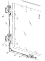
- a window wing 11 is shown, which is provided with a locking system for securing the window sash 11.
- the locking system comprises a window handle 13, a corner gear 15, a first anti-tilt device 17, an identical second anti-tilt device 19, and a plurality of connecting rods 21, 21 ', 21 ", of which in each case a connecting rod 21, 21', 21" connecting between the window handle 13 and the corner gear 15, the corner gear 15 and the first anti-tip device 17, and the first anti-tip device 17 and the second anti-tip device 19 is arranged.
- covers for the corner gear 15, the anti-tippers 17, 19 and the connecting rods 21, 21 ', 21 not shown.
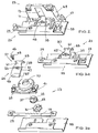
- the anti-tip device 17 or 19, the in Fig. 2 is shown in detail, comprises a locking unit 23 and a securing unit 25, which is attached via a fastening strip 27 on a the window sash 11 associated window frame (not shown).
- the locking unit 23 is attached to the window sash 11 so that the locking unit 23 can be displaced by opening or tilting the window sash 11 relative to the securing unit 25.
- the securing unit 25 remains unmoved in its position.
- the locking unit 23, which in Fig. 3 is shown in detail, first comprises a gear 29, 31, which has a rack 29 and a gear 31 engaging in the rack 29. In this way, a linear movement of the rack 29 along the longitudinal direction of the rack 29 can be converted into a rotational movement of the gear 31.
- the gear 31 is rotatably connected to a with respect to the gear 31 coaxially arranged drive pulley 33.
- the drive pulley 33 has on its side facing away from the gear 31 a driving cam 35 and a driver bore 37.
- the driver cam 35 and the driver bore 37 are each arranged eccentrically and opposite to each other with respect to the axis of rotation 79 of the drive pulley 33.
- the transmission 29, 31 is covered by an inner housing portion 39, wherein at the rear of the inner housing portion 39, a straight guide portion 41 for the rack 29 of the transmission 29, 31 is formed.
- the inner housing section 39 has an opening 77, through which a rotary latch 43 arranged on the front side of the inner housing section 39 is non-rotatably connected to the drive disk 33.
- the pivot axis 45 passing through the center of the rotary latch 43 and perpendicular to the plane of movement of the rotary latch 43 is arranged eccentrically with respect to the drive pulley axis of rotation 79.
- the rotary latch 43 has a central bore 47, through the center of the rotary latch axis 45 extends, wherein a fastening screw 49 is provided, which passes through the central bore 47 of the rotary latch 43 into the correspondingly threaded driving bore 37 of the Drive pulley 33 is inserted.
- a fastening screw 49 is provided, which passes through the central bore 47 of the rotary latch 43 into the correspondingly threaded driving bore 37 of the Drive pulley 33 is inserted.
- the drive cam 35 of the drive pulley 33 is inserted into a side bore 51 formed laterally of the central bore 47 in the rotary latch 43.
- the rotary latch 43 further has a second side bore 53, which is arranged opposite to the aforementioned side bore 51 with respect to the rotary latch axis 45, so that it is basically also possible to insert the drive cam 35 of the drive pulley 33 into the second side bore 53 of the rotary latch 43. hereby Optionally, a left-hand operation or a right-hand operation of the locking unit 23 can be defined.
- the locking unit 23 comprises a housing 55, from which the rack 29, the gear 31, the drive pulley 33, the inner housing portion 39 and the rotary latch 43 are received, and via which the locking unit 23 is attached to the window sash 11.
- the housing 55 is made of a one-piece stamped and bent part made of steel. A cover for the locking unit 23 is not shown for clarity.
- the rotary latch 43 has at its in Fig. 3 upper, first end 57 has a T-shaped locking portion 59 with a vertical leg 61 and a horizontal leg 63.
- the locking portion 59 is angled at its outer end perpendicular to the plane of extension of the rotary latch 43 to the rear (ie in the direction of the window frame).
- second end 65 with respect to the rotary latch axis 45 in the Fig. 3 upper, first end 57 is opposite, the rotary latch 43 also has a locking portion 67, which in turn is angled at its outer end perpendicular to the plane of extension of the rotary latch 43 to the rear.
- the fuse unit 25, which is in Fig. 4 is shown in detail, has a made of a one-piece stamped and bent part made of hardened steel housing 69 which is mounted on the mounting bar 27 on the window frame.
- the housing 69 has at its in Fig. 4 lower side of an engagement track 71, in which a securing track 73 opens such that the two webs 71, 73 together form a T-shape.
- the securing track 73 runs perpendicular to the engagement track 71.
- a support section 75 is in the engagement track 71 before.
- the two webs 71, 73 are made by punching.
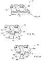
- the rotary latch 43 of the locking unit 23 is between a first locking position, the in Fig. 2 and Fig. 5a is shown, a second locking position, the in Fig. 5b is shown, and a release position (not shown) pivotally when the locking unit 23 is in a closed position relative to the securing unit 25, that is, when the window sash 11 is closed, that is neither opened nor tilted.
- a release position pivotally when the locking unit 23 is in a closed position relative to the securing unit 25, that is, when the window sash 11 is closed, that is neither opened nor tilted.
- Fig. 5 only the rotary latch 43 is shown by the locking unit 23.
- the pivoting of the rotary latch 43 is triggered by a linear movement of the rack 29, wherein the linear movement of the rack 29 via the gear 29, 31 is converted into a rotational movement of the gear 31.
- the rotational movement of the gear 31 results in a rotational movement of the drive disk 33 and thus in a pivoting movement of the rotary bolt 43 rotatably connected to the drive disk 33.
- the rotary latch 43 is moved along the securing track 73 of the securing unit 25 until the rotary latch 43 in the tilted position to that of the engagement track 71 opposite end of the securing track 73 strikes.
- This is made possible in particular by the fact that the width of the vertical leg 61 of the T-shaped locking portion 59 of the first end 57 of the rotary latch 43 is smaller than the width of the securing track 73.
- the rotary latch 43 In the second locking position ( Fig. 5b ) engages the second end 65 of the rotary latch 43 in the engagement track 71 of the securing unit 25, wherein the angled end of the locking portion 67 of the second end 65, the support portion 75 of the securing track 73 engages behind.
- the rotary latch 43 In the second locking position, the rotary latch 43 is in a respect to the previously described first locking position by 180 ° about the drive pulley rotational axis 79 pivoted position.
- Tilting of the sash 11 is not possible in the second locking position, i. a method of the rotary latch 43 of the locking unit 23 along the securing track 71 of the securing unit 25 is blocked because the width of the locking portion 67 of the second end 65 of the rotary latch 43 is greater than the width of the securing track 73rd
- the rotary latch 43 In the release position, the rotary latch 43 is disengaged from the securing track 71 of the securing unit 25, ie neither of the two ends 57, 65 of the rotary latch 43 engages in the securing track 71 of the securing unit 25.
- the rotary latch 43 assumes a position in which the longitudinal axis of the rotary latch 43 (connecting line between the two ends 57, 65) parallel to the longitudinal axis of the rack 29th or parallel to the longitudinal extension of the engagement track 71 of the securing unit 25 extends. In the release position of the rotary latch 43 therefore a complete opening of the window sash 11 is possible.
- the rotary latch axis 45 passes through a semicircular curved path when the rotary latch 43 from the first locking position on the release position to the second locking position, or vice versa , is pivoted.
- the eccentric arrangement of the rotary latch axis 45 to the drive pulley axis of rotation 79 is selected such that the rotary latch axis 45 in the release position has a greater distance from the engagement track 71 than in the first locking position and in the second locking position.
- the linear movement of the rack 29, by which the pivoting of the rotary latch 43 of the anti-tippers 17, 19 is effected, is triggered by a rotary actuation of the window handle 13.
- the window handle 13 has for this purpose to the gear 29, 31 of the locking unit 23 analog transmission (not shown), which converts a pivotal movement of the window handle 13 in a linear movement of the arranged between the window handle 13 and the corner gear 15 connecting rod 21.
- the corner gear 15 in turn sets the linear movement of the between Window handle 13 and the corner gear 15 arranged connecting rod 21 in a linear movement of arranged between the corner gear 15 and the first anti-tipper 17 connecting rod 21 ', whereby a linear movement of the rack 29 of the first anti-tip device 17 is triggered.
- the rack 29 of the first anti-tip device 17 transmits the linear movement to the connecting rod 21 "arranged between the first anti-tilt device 17 and the second anti-tilt device 19, whereby a linear movement of the rack 29 of the second anti-tilt device 19 is triggered.
- the connecting rods 21, 21 ', 21 are each provided with two-axis joints at their two ends, and the connecting rods 21, 21', 21" are designed as threaded rods which can easily be cut to length and are each fine-adjustable with a nut.
- the connecting rod 21 is in Fig. 1 not yet fully assembled.
- the described anti-tilt device for a window sash or the described locking system for securing the tilted position of a window sash makes it possible to increase the safety against breakage of a tilted window.
Landscapes
- Engineering & Computer Science (AREA)
- Mechanical Engineering (AREA)
- Wing Frames And Configurations (AREA)
- Power-Operated Mechanisms For Wings (AREA)
Applications Claiming Priority (1)
| Application Number | Priority Date | Filing Date | Title |
|---|---|---|---|
| DE102007035123.4A DE102007035123B4 (de) | 2007-07-27 | 2007-07-27 | Kippsicherung |
Publications (2)
| Publication Number | Publication Date |
|---|---|
| EP2022916A2 true EP2022916A2 (fr) | 2009-02-11 |
| EP2022916A3 EP2022916A3 (fr) | 2011-08-03 |
Family
ID=39832198
Family Applications (1)
| Application Number | Title | Priority Date | Filing Date |
|---|---|---|---|
| EP08011348A Withdrawn EP2022916A3 (fr) | 2007-07-27 | 2008-06-23 | Sécurité contre le renversement |
Country Status (2)
| Country | Link |
|---|---|
| EP (1) | EP2022916A3 (fr) |
| DE (1) | DE102007035123B4 (fr) |
Families Citing this family (2)
| Publication number | Priority date | Publication date | Assignee | Title |
|---|---|---|---|---|
| CN104120929B (zh) * | 2013-04-27 | 2017-03-22 | 深圳市早田门窗技术发展有限公司 | 门窗锁紧定位装置 |
| CN116696166A (zh) * | 2023-07-25 | 2023-09-05 | 中车长江车辆有限公司 | 一种车门锁闭机构、车门及铁路保温车 |
Family Cites Families (5)
| Publication number | Priority date | Publication date | Assignee | Title |
|---|---|---|---|---|
| DE2439321A1 (de) * | 1974-08-16 | 1976-02-26 | Fuhr C Fa | In form eines fensters, einer tuere oder dergleichen ausgebildeter drehfluegel |
| IT1058039B (it) | 1976-03-31 | 1982-04-10 | Rossi R De | Calcio di sicurezza ad inserzione automatica per porte di ingresso di abitazioni e uffici |
| ES467065A1 (es) | 1978-01-31 | 1979-08-01 | Tarragona Corbella Fco Javier | Perfeccionamientos en las disposiciones de cierre de seguri-dad para puertas |
| DE8906629U1 (de) * | 1989-05-30 | 1989-08-31 | Nothelfer, Josef, 8000 München | Multifunktionaler Fenstergriff (Olive) mit gleichzeitiger Sperr- und Kippfunktion |
| DE4207345C2 (de) | 1992-03-07 | 2002-10-10 | Melchert Beschlaege | Mittels Griffhandhabe zu betätigender Sperrbügel-Beschlag an Fenstern, Türen oder dergleichen |
-
2007
- 2007-07-27 DE DE102007035123.4A patent/DE102007035123B4/de not_active Expired - Fee Related
-
2008
- 2008-06-23 EP EP08011348A patent/EP2022916A3/fr not_active Withdrawn
Also Published As
| Publication number | Publication date |
|---|---|
| DE102007035123B4 (de) | 2022-09-08 |
| EP2022916A3 (fr) | 2011-08-03 |
| DE102007035123A1 (de) | 2009-01-29 |
Similar Documents
| Publication | Publication Date | Title |
|---|---|---|
| WO1991017334A1 (fr) | Fermeture a levier pivotant verrouillee par une serrure a pompe | |
| EP2133494B1 (fr) | Dispositif de verrouillage de sécurité doté d'un dispositif de déverrouillage de secours | |
| EP1022421B1 (fr) | Dispositif déflecteur pour panneau basculant ou oscillo-battant monté pivotant sur un cadre | |
| DE102007035123B4 (de) | Kippsicherung | |
| EP0688930B1 (fr) | Serrure pour portes ou fenêtres | |
| EP3913171B1 (fr) | Entraînement de verrouillage et/ou de positionnement pour une fenêtre, une porte ou similaire | |
| EP1149974A1 (fr) | Dispositif de blocage | |
| DE102014010265B4 (de) | Riegelwerk für Wertbehältnisse | |
| EP1746235B1 (fr) | Ensemble de ferrure | |
| DE3920498C2 (de) | Mehrfachverriegelung | |
| EP3348773A1 (fr) | Dispositif d'ouverture, de fermeture et de verrouillage des lamelles d'une structure en lamelles | |
| EP0601294A1 (fr) | Serrure complémentaire de securité pour battant de fenêtres, portes ou similaires | |
| EP4174266A1 (fr) | Agencement de battant | |
| DE9417227U1 (de) | Verriegelungsschloß | |
| EP0735221A2 (fr) | Dispositif de sécurité pour partie charnière de portes | |
| DE3111579A1 (de) | Drehkippfenster | |
| EP1231345B1 (fr) | Dispositif de verrouillage et renvoi d'angle contrôlés | |
| EP0199270A2 (fr) | Dispositif pour maintenir une porte ou une fenêtre entrouverte dans au moins une position | |
| EP4610458B1 (fr) | Barre de poussée anti-panique avec ouverture de porte | |
| EP1790805B1 (fr) | Mécanisme d'actionnement à levier pour une crémone | |
| EP1818489A1 (fr) | Fenêtre ou porte de sécurité inhibant l'effraction | |
| EP2221435B1 (fr) | Serrure complémentaire de sécurité pour fenêtres | |
| EP4174264B1 (fr) | Agencement de battant | |
| EP1130200B1 (fr) | Dispositif de verrouillage | |
| DE4028992A1 (de) | Tuerschloss, insbesondere fuer kraftfahrzeuge |
Legal Events
| Date | Code | Title | Description |
|---|---|---|---|
| PUAI | Public reference made under article 153(3) epc to a published international application that has entered the european phase |
Free format text: ORIGINAL CODE: 0009012 |
|
| AK | Designated contracting states |
Kind code of ref document: A2 Designated state(s): AT BE BG CH CY CZ DE DK EE ES FI FR GB GR HR HU IE IS IT LI LT LU LV MC MT NL NO PL PT RO SE SI SK TR |
|
| AX | Request for extension of the european patent |
Extension state: AL BA MK RS |
|
| PUAL | Search report despatched |
Free format text: ORIGINAL CODE: 0009013 |
|
| AK | Designated contracting states |
Kind code of ref document: A3 Designated state(s): AT BE BG CH CY CZ DE DK EE ES FI FR GB GR HR HU IE IS IT LI LT LU LV MC MT NL NO PL PT RO SE SI SK TR |
|
| AX | Request for extension of the european patent |
Extension state: AL BA MK RS |
|
| RIC1 | Information provided on ipc code assigned before grant |
Ipc: E05C 17/04 20060101AFI20110627BHEP |
|
| 17P | Request for examination filed |
Effective date: 20120203 |
|
| AKX | Designation fees paid |
Designated state(s): AT BE BG CH CY CZ DE DK EE ES FI FR GB GR HR HU IE IS IT LI LT LU LV MC MT NL NO PL PT RO SE SI SK TR |
|
| GRAP | Despatch of communication of intention to grant a patent |
Free format text: ORIGINAL CODE: EPIDOSNIGR1 |
|
| RIC1 | Information provided on ipc code assigned before grant |
Ipc: E05C 17/00 20060101ALI20120410BHEP Ipc: E05C 9/18 20060101AFI20120410BHEP |
|
| STAA | Information on the status of an ep patent application or granted ep patent |
Free format text: STATUS: THE APPLICATION IS DEEMED TO BE WITHDRAWN |
|
| 18D | Application deemed to be withdrawn |
Effective date: 20120918 |