EP2022946A1 - Turbotriebwerk, das einen Stromgenerator umfasst, der ins Gebläse eingebaut ist, und Montageverfahren besagten Generators unter dem Gebläse - Google Patents
Turbotriebwerk, das einen Stromgenerator umfasst, der ins Gebläse eingebaut ist, und Montageverfahren besagten Generators unter dem Gebläse Download PDFInfo
- Publication number
- EP2022946A1 EP2022946A1 EP08161954A EP08161954A EP2022946A1 EP 2022946 A1 EP2022946 A1 EP 2022946A1 EP 08161954 A EP08161954 A EP 08161954A EP 08161954 A EP08161954 A EP 08161954A EP 2022946 A1 EP2022946 A1 EP 2022946A1
- Authority
- EP
- European Patent Office
- Prior art keywords
- fan
- current generator
- rotor
- turbojet engine
- low
- Prior art date
- Legal status (The legal status is an assumption and is not a legal conclusion. Google has not performed a legal analysis and makes no representation as to the accuracy of the status listed.)
- Granted
Links
Images

Classifications
-
- F—MECHANICAL ENGINEERING; LIGHTING; HEATING; WEAPONS; BLASTING
- F01—MACHINES OR ENGINES IN GENERAL; ENGINE PLANTS IN GENERAL; STEAM ENGINES
- F01D—NON-POSITIVE DISPLACEMENT MACHINES OR ENGINES, e.g. STEAM TURBINES
- F01D15/00—Adaptations of machines or engines for special use; Combinations of engines with devices driven thereby
- F01D15/10—Adaptations for driving, or combinations with, electric generators
-
- F—MECHANICAL ENGINEERING; LIGHTING; HEATING; WEAPONS; BLASTING
- F02—COMBUSTION ENGINES; HOT-GAS OR COMBUSTION-PRODUCT ENGINE PLANTS
- F02C—GAS-TURBINE PLANTS; AIR INTAKES FOR JET-PROPULSION PLANTS; CONTROLLING FUEL SUPPLY IN AIR-BREATHING JET-PROPULSION PLANTS
- F02C7/00—Features, components parts, details or accessories, not provided for in, or of interest apart form groups F02C1/00 - F02C6/00; Air intakes for jet-propulsion plants
- F02C7/04—Air intakes for gas-turbine plants or jet-propulsion plants
-
- F—MECHANICAL ENGINEERING; LIGHTING; HEATING; WEAPONS; BLASTING
- F02—COMBUSTION ENGINES; HOT-GAS OR COMBUSTION-PRODUCT ENGINE PLANTS
- F02K—JET-PROPULSION PLANTS
- F02K3/00—Plants including a gas turbine driving a compressor or a ducted fan
- F02K3/02—Plants including a gas turbine driving a compressor or a ducted fan in which part of the working fluid by-passes the turbine and combustion chamber
- F02K3/04—Plants including a gas turbine driving a compressor or a ducted fan in which part of the working fluid by-passes the turbine and combustion chamber the plant including ducted fans, i.e. fans with high volume, low pressure outputs, for augmenting the jet thrust, e.g. of double-flow type
- F02K3/06—Plants including a gas turbine driving a compressor or a ducted fan in which part of the working fluid by-passes the turbine and combustion chamber the plant including ducted fans, i.e. fans with high volume, low pressure outputs, for augmenting the jet thrust, e.g. of double-flow type with front fan
-
- Y—GENERAL TAGGING OF NEW TECHNOLOGICAL DEVELOPMENTS; GENERAL TAGGING OF CROSS-SECTIONAL TECHNOLOGIES SPANNING OVER SEVERAL SECTIONS OF THE IPC; TECHNICAL SUBJECTS COVERED BY FORMER USPC CROSS-REFERENCE ART COLLECTIONS [XRACs] AND DIGESTS
- Y02—TECHNOLOGIES OR APPLICATIONS FOR MITIGATION OR ADAPTATION AGAINST CLIMATE CHANGE
- Y02T—CLIMATE CHANGE MITIGATION TECHNOLOGIES RELATED TO TRANSPORTATION
- Y02T50/00—Aeronautics or air transport
- Y02T50/60—Efficient propulsion technologies, e.g. for aircraft
Definitions
- the invention relates to a gas turbine engine with an upstream fan and a method for mounting an electric current generator in the turbojet engine.
- Part of the power generated by an aeronautical turbojet engine is used to feed different organs, both of the turbojet engine but also of the aircraft whose turbojet engine is involved in propulsion.
- HP high pressure compressor
- compressed air is used, in particular to ensure the pressurization and conditioning of the cabin of the aircraft, or defrosting.
- Another part of this power is taken mechanically on the shaft of the stage HP of the turbojet, to drive the input shaft of an accessory box placed on a turbojet engine casing.
- This input shaft is rotated by a transmission shaft extending in a structural arm of the housing and itself driven by a pinion integral with the HP shaft.
- the current trend is to increase the installed electrical power, and thus the mechanical power draws on the engine.
- He is also known by the patent application W02007 / 036202 to mount an electric current generator in the turbojet engine body.
- the generator is composed of a stator element, disposed circumferentially in the compression casing of the turbojet, and rotor elements fixed to the blade ends integral with the HP shaft and rotated in the compression housing of the turbojet engine.
- the rotational movement of the rotor elements induces a current in the stator element which is transmitted to the different equipment to be powered.
- a current generator is difficult to access and involves partially dismantling the turbojet engine during its replacement or maintenance.
- the compressor housing is of reduced size which complicates the routing of the generated current to the different equipment.
- the Applicant has proposed a double-body gas turbine engine comprising a high-pressure rotor and a low-pressure rotor, the low-pressure rotor shaft being connected, at its upstream end, to a fan housed in a fan casing, characterized in that it comprises, upstream of the fan, a fixed bonnet element centered on the axis of the motor, on which is mounted an electric current generator arranged to collect the mechanical power of the low pressure rotor shaft and convert it into electrical power.
- the turbojet advantageously makes it possible not to draw power on the HP rotor shaft.
- the current generator is easy to access which allows its replacement in a limited time by dismantling a minimum of turbojet parts.
- the current generator is placed upstream of the fan, in a cold zone of the turbojet, which reduces its cooling requirements and therefore its mass.
- the current generator comprises a stator element connected to the fixed hood element, a rotor element being driven by the upstream end of the low pressure rotor shaft.
- the turbojet comprises a fan disk on which are mounted the fan blades.
- a rotor element of the current generator is rotated by a journal integral with said fan disk.
- the bonnet element is advantageously connected to the fan casing by radial retaining arms.
- the radial arms make it possible to fix the stator element of the generator without creating significant structural modifications of the turbojet engine.
- Lubrication lines of the current generator and electrical cables are formed in the radial support arms.
- power transmission gears are respectively formed on the rotor element of the current generator and on the upstream end of the low pressure rotor shaft, the gears meshing with each other. for transmitting the rotational movement of the low pressure rotor shaft to the rotor element of the current generator.
- the assembly of the generator is simple and is performed upstream of the turbojet engine.
- the manipulated parts are of reduced size and low mass which allows a quick replacement of the current generator.
- the turbojet engine of the invention is a double-body gas turbine engine 100, comprising a low pressure rotor (LP) and a high pressure rotor (HP) 1, rotatably mounted about the axis X3 of the turbojet engine.
- LP low pressure rotor
- HP high pressure rotor
- the turbojet engine comprises functionally, from upstream to downstream in the direction of flow of gases, a fan 10, a compressor, a combustion chamber, a turbine and an exhaust nozzle.
- a fan 10 As it is dual body, it includes a BP compressor, upstream of an HP compressor, and an HP turbine, upstream of a LP turbine.
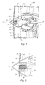
- the blower 10, figure 1 comprises a fan disk 19 fixed by a flange to a pin 15, itself supported by a bearing integral with the intermediate casing, the pin 15 being here secured to the low pressure shaft 2.
- the fan 10 further comprises a movable cowl element 11 which is fixed on the fan disk 19.
- the movable cowl element 11 is of frustoconical shape and serves to guide the air intake stream.
- a fixed hood element 12 is disposed upstream of the movable hood element 11.
- the fan 10 is rotated in the fan casing 14 by the rotor shaft BP 2 rotatably connected to the movable cowl element 11.
- a housing 13 is formed in the movable cowl element 11.
- an electric current generator 20 is mounted on the fixed hood element 12, the generator 20 comprising a stator element 21, integrally connected to the fixed hood element 12, and a rotor element 22 free to rotate with respect to the fixed hood element 12.
- the rotor element 22 is here an electromagnet extending axially along the axis X3.
- the stator element 21 is composed of windings which extend coaxially and externally to the rotor element 22.
- a bearing 23 rotatably supports the rotor element 21 in the stator element 21.
- Radial holding arms 16 structurally connect the fixed hood element 12 to the fan casing 14, the stator element 21 of the current generator 20 thus remaining stationary during the rotation of the fan blades 18.
- the holding arms 16 are secured by a flange on the fan casing 14.
- the holding arms 16 are advantageously hollow and can accommodate the lubrication ducts 41 of the current generator 20 and the electric cables 42 shown in FIG. figure 2 .
- the upper holding arm 16 is shown in transparency over part of its length in order to allow the observation of the lubrication ducts 41 of the current generator 20 and the electric cables 42.
- the lubricant ducts 41 of the current generator 20 make it possible to convey a lubricant, such as oil, from an oil tank, placed downstream of the fan, to the current generator 20 to allow cooling and the lubrication of the current generator 20.
- a lubricant such as oil
- the electric cables 42 make it possible to conduct the current generated in the windings 21 to electrical equipment located downstream of the motor.
- the holding arms 16 of the fixed hood element 12 are here shaped so as to conduct the inlet air stream to the fan blades 18.
- the holding arms 16 are here three in number, angularly spaced apart from each other. 120 degrees. It goes without saying that this number can change according to the configuration of the engine.
- the rotor element 22 is directly connected to the upstream end of the low-pressure rotor shaft 2.
- Conical transmission gears 25, 26 are respectively formed on the rotor element 22 of the generator current 20 and on the upstream end of the low pressure rotor shaft 2, the pinions 25, 26 meshing with each other to transmit the rotational movement of the low pressure shaft 2 to the rotor element 22 of the current generator 20.
- the low-pressure rotor shaft 2 is rotated by the low-pressure turbine of the turbojet engine 100.
- the low-pressure rotor shaft 2 drives the electromagnet 22 in rotation around the axis X3 and induces an electric current in the windings 21 of the current generator 20.
- the current is conveyed by the arms 16 for holding the fixed cover element 12 via the electric cables 42 arranged in the arms 16, the equipment located mainly downstream of the fan then being supplied with electric current.
- an additional journal 17 is mounted between the fan disk 19 and the rotor element 22 of the current generator 20, the fan disk 19 supporting the fan blades 18.
- the pin 17 is connected by a nut screw connection to the fan disk 19 and to the rotor element 22.
- the fixing of the current generator 20 with the fixed hood element 12 remains identical; only the drive means of the rotor element 22 differs from the previous embodiment.
- the invention also relates to the method of mounting the current generator 20 in the turbojet engine 100.
- the current generator 20 is mounted on the fixed hood element 12.
- the current generator 20 is here screwed with the hood.
- the stationary hood element 12 is arranged on the fan 10 so that the rotor element 22 of the generator 20 comes into correspondence with the upstream end of the shaft of the low-pressure rotor 2.
- the conical power transmission pinion 25 of the stator element 22 is brought into correspondence with the conical power transmission pinion 26 of the low-pressure rotor shaft 2.
- the fixed hood element 12 is immobilized on the fan casing 14 with the radial holding arms 16.
- the lubrication ducts 41 of the current generator 20 are connected to the current generator 20 in order to supply the current generator 20 with oil, the electric cables 42 being connected to the windings of the stator element 21 of the current generator 20 in order to to convey the current to the various equipment of the aircraft.
Landscapes
- Engineering & Computer Science (AREA)
- Chemical & Material Sciences (AREA)
- Combustion & Propulsion (AREA)
- Mechanical Engineering (AREA)
- General Engineering & Computer Science (AREA)
- Connection Of Motors, Electrical Generators, Mechanical Devices, And The Like (AREA)
- Structures Of Non-Positive Displacement Pumps (AREA)
Applications Claiming Priority (1)
| Application Number | Priority Date | Filing Date | Title |
|---|---|---|---|
| FR0705757A FR2919896B1 (fr) | 2007-08-07 | 2007-08-07 | Turboreacteur comprenant un generateur de courant monte dans la soufflante et un procede de montage dudit generateur dans la soufflante |
Publications (2)
| Publication Number | Publication Date |
|---|---|
| EP2022946A1 true EP2022946A1 (de) | 2009-02-11 |
| EP2022946B1 EP2022946B1 (de) | 2010-06-16 |
Family
ID=39357233
Family Applications (1)
| Application Number | Title | Priority Date | Filing Date |
|---|---|---|---|
| EP08161954A Active EP2022946B1 (de) | 2007-08-07 | 2008-08-06 | Turbotriebwerk, dass einen Stromgenerator umfasst, der ins Gebläse eingebaut ist, und Montageverfahren besagten Generators unter dem Gebläse |
Country Status (7)
| Country | Link |
|---|---|
| US (1) | US8026624B2 (de) |
| EP (1) | EP2022946B1 (de) |
| JP (1) | JP5378726B2 (de) |
| CA (1) | CA2638808C (de) |
| DE (1) | DE602008001537D1 (de) |
| FR (1) | FR2919896B1 (de) |
| RU (1) | RU2485328C2 (de) |
Cited By (3)
| Publication number | Priority date | Publication date | Assignee | Title |
|---|---|---|---|---|
| EP2412939A1 (de) * | 2010-07-30 | 2012-02-01 | Hamilton Sundstrand Corporation | In Lüfter eingebetteter Stromgenerator |
| EP2947278B1 (de) | 2014-05-20 | 2017-07-12 | United Technologies Corporation | Getriebefan mit schnelllaufendem generator |
| US20220268871A1 (en) * | 2021-02-24 | 2022-08-25 | Bluehalo, Llc | System and method for a digitally beamformed phased array feed |
Families Citing this family (20)
| Publication number | Priority date | Publication date | Assignee | Title |
|---|---|---|---|---|
| DE102010014968A1 (de) | 2010-04-14 | 2011-10-20 | Mtu Aero Engines Gmbh | Mehrwelliges Triebwerk mit Tandem-Generator |
| DE102010049885B4 (de) * | 2010-11-01 | 2015-06-25 | Rolls-Royce Deutschland Ltd & Co Kg | Strahltriebwerk |
| US9200592B2 (en) * | 2011-06-28 | 2015-12-01 | United Technologies Corporation | Mechanism for turbine engine start from low spool |
| US8723349B2 (en) | 2011-10-07 | 2014-05-13 | General Electric Company | Apparatus for generating power from a turbine engine |
| US8723385B2 (en) | 2011-10-07 | 2014-05-13 | General Electric Company | Generator |
| FR2989734B1 (fr) * | 2012-04-24 | 2014-04-18 | Snecma | Turboreacteur incorporant des generateurs thermoelectriques |
| WO2014158240A2 (en) | 2013-03-14 | 2014-10-02 | Rolls-Royce Corporation | Hybrid turbo electric aero-propulsion system control |
| GB2526428A (en) * | 2014-04-15 | 2015-11-25 | Whoosh 2013 Ltd | Power generating Apparatus |
| FR3024755B1 (fr) * | 2014-08-08 | 2019-06-21 | Safran Aircraft Engines | Hybridation des compresseurs d'un turboreacteur |
| US10377498B2 (en) * | 2016-01-21 | 2019-08-13 | The Boeing Company | Aircraft and associated method for providing electrical energy to an anti-icing system |
| FR3054265B1 (fr) * | 2016-07-22 | 2018-07-13 | Safran Aircraft Engines | Entrainement d'un rotor d'equipement dans une turbomachine |
| US10071811B2 (en) * | 2016-08-22 | 2018-09-11 | General Electric Company | Embedded electric machine |
| US10308366B2 (en) | 2016-08-22 | 2019-06-04 | General Electric Company | Embedded electric machine |
| US11156128B2 (en) | 2018-08-22 | 2021-10-26 | General Electric Company | Embedded electric machine |
| FR3087822B1 (fr) * | 2018-10-26 | 2020-11-06 | Safran Aircraft Engines | Turbomachine a machine electrique comportant un anneau de rotor accole a la soufflante |
| US12149154B2 (en) | 2021-07-22 | 2024-11-19 | General Electric Company | Electric machine having a hybrid insulative-conductive manifold |
| GB202307055D0 (en) | 2023-05-12 | 2023-06-28 | Rolls Royce Plc | An accessory power module |
| US12140152B1 (en) * | 2023-08-30 | 2024-11-12 | Rtx Corporation | Nose cone/spinner power takeoff |
| US12595737B2 (en) * | 2023-12-21 | 2026-04-07 | Rtx Corporation | Two piece retractable engine center body for balancing |
| DE102024122086A1 (de) * | 2024-08-02 | 2026-02-05 | MTU Aero Engines AG | Gasturbinenbaugruppe und Verfahren zum Herstellen, Warten und/oder Betreiben der Gasturbinenbaugruppe |
Citations (7)
| Publication number | Priority date | Publication date | Assignee | Title |
|---|---|---|---|---|
| GB1174969A (en) | 1967-10-20 | 1969-12-17 | Rolls Royce | Gas Turbine Engine Provided with an Alternator |
| US3900274A (en) * | 1974-06-25 | 1975-08-19 | Gen Electric | Remote controlled actuation system for the rotor of a gas turbine engine |
| US5282719A (en) | 1991-05-13 | 1994-02-01 | Alliedsignal Inc. | Quad mode fan pitch actuation system for a gas turbine engine |
| EP1662636A2 (de) * | 2004-11-25 | 2006-05-31 | Snecma | Turbomaschine mit einem integrierten Stromgenerator |
| FR2882096A1 (fr) | 2005-02-11 | 2006-08-18 | Snecma Moteurs Sa | Turbomoteur a double corps avec des moyens de prise de mouvement sur les rotors basse pression et haute pression, module de prise de mouvement pour le turbomoteur et procede de montage du turbomoteur |
| GB2425572A (en) * | 2005-04-29 | 2006-11-01 | Gen Electric | Gas turbine starter-generator |
| WO2007036202A1 (de) | 2005-09-28 | 2007-04-05 | Mtu Aero Engines Gmbh | Strahltriebwerk mit einer integrierten elektrischen motor/generatoreinheit |
Family Cites Families (14)
| Publication number | Priority date | Publication date | Assignee | Title |
|---|---|---|---|---|
| US4490622A (en) * | 1979-05-11 | 1984-12-25 | Osborn Norbert L | Turbocharger and adaptations thereof |
| EP0302508B1 (de) * | 1987-08-06 | 1990-10-24 | Mtu Motoren- Und Turbinen-Union MàNchen Gmbh | Energieversorgungsanlage |
| RU2014482C1 (ru) * | 1990-12-29 | 1994-06-15 | Варюхин Александр Сергеевич | Устройство регулирования тяги газотурбинного двигателя |
| IT1246759B (it) * | 1990-12-31 | 1994-11-26 | Sgs Thomson Microelectronics | Struttura integrata di transistore bipolare di potenza e di transistore bipolare di bassa tensione nelle configurazioni ''emitter switching'' o ''semi-ponte'' e relativi processi di fabbricazione. |
| JP3244771B2 (ja) * | 1992-06-04 | 2002-01-07 | 東海旅客鉄道株式会社 | リニアモータカー |
| US5497615A (en) * | 1994-03-21 | 1996-03-12 | Noe; James C. | Gas turbine generator set |
| GB9606546D0 (en) * | 1996-03-28 | 1996-06-05 | Rolls Royce Plc | Gas turbine engine system |
| GB9904221D0 (en) * | 1999-02-25 | 1999-04-21 | Rolls Royce Plc | Gas turbine engine bearing arrangement |
| US20070199331A1 (en) * | 2003-09-19 | 2007-08-30 | Maguire Alan R | Power transmission arrangement |
| RU44148U1 (ru) * | 2004-09-29 | 2005-02-27 | Открытое акционерное общество "Научно-производственное объединение "Сатурн" | Газотурбинный двигатель |
| US7134271B2 (en) * | 2004-11-05 | 2006-11-14 | General Electric Company | Thrust vectoring aft FLADE engine |
| IL165233A (en) * | 2004-11-16 | 2013-06-27 | Israel Hirshberg | Energy conversion facility |
| US7948105B2 (en) * | 2007-02-01 | 2011-05-24 | R&D Dynamics Corporation | Turboalternator with hydrodynamic bearings |
| JP4648347B2 (ja) * | 2007-02-23 | 2011-03-09 | 三菱重工業株式会社 | ハイブリッド排気タービン過給機 |
-
2007
- 2007-08-07 FR FR0705757A patent/FR2919896B1/fr not_active Expired - Fee Related
-
2008
- 2008-07-25 US US12/179,911 patent/US8026624B2/en active Active
- 2008-08-04 JP JP2008200449A patent/JP5378726B2/ja active Active
- 2008-08-06 CA CA2638808A patent/CA2638808C/fr active Active
- 2008-08-06 EP EP08161954A patent/EP2022946B1/de active Active
- 2008-08-06 DE DE602008001537T patent/DE602008001537D1/de active Active
- 2008-08-07 RU RU2008132629/06A patent/RU2485328C2/ru active
Patent Citations (7)
| Publication number | Priority date | Publication date | Assignee | Title |
|---|---|---|---|---|
| GB1174969A (en) | 1967-10-20 | 1969-12-17 | Rolls Royce | Gas Turbine Engine Provided with an Alternator |
| US3900274A (en) * | 1974-06-25 | 1975-08-19 | Gen Electric | Remote controlled actuation system for the rotor of a gas turbine engine |
| US5282719A (en) | 1991-05-13 | 1994-02-01 | Alliedsignal Inc. | Quad mode fan pitch actuation system for a gas turbine engine |
| EP1662636A2 (de) * | 2004-11-25 | 2006-05-31 | Snecma | Turbomaschine mit einem integrierten Stromgenerator |
| FR2882096A1 (fr) | 2005-02-11 | 2006-08-18 | Snecma Moteurs Sa | Turbomoteur a double corps avec des moyens de prise de mouvement sur les rotors basse pression et haute pression, module de prise de mouvement pour le turbomoteur et procede de montage du turbomoteur |
| GB2425572A (en) * | 2005-04-29 | 2006-11-01 | Gen Electric | Gas turbine starter-generator |
| WO2007036202A1 (de) | 2005-09-28 | 2007-04-05 | Mtu Aero Engines Gmbh | Strahltriebwerk mit einer integrierten elektrischen motor/generatoreinheit |
Cited By (41)
| Publication number | Priority date | Publication date | Assignee | Title |
|---|---|---|---|---|
| EP2412939A1 (de) * | 2010-07-30 | 2012-02-01 | Hamilton Sundstrand Corporation | In Lüfter eingebetteter Stromgenerator |
| US20120025676A1 (en) * | 2010-07-30 | 2012-02-02 | Poisson Richard A | Fan embedded power generator |
| US8522522B2 (en) * | 2010-07-30 | 2013-09-03 | Hamilton Sundstrand Corporation | Fan embedded power generator |
| EP2947278B1 (de) | 2014-05-20 | 2017-07-12 | United Technologies Corporation | Getriebefan mit schnelllaufendem generator |
| US11236632B2 (en) | 2014-05-20 | 2022-02-01 | Raytheon Technologies Corporation | Geared turbofan with high speed generator |
| US20220268871A1 (en) * | 2021-02-24 | 2022-08-25 | Bluehalo, Llc | System and method for a digitally beamformed phased array feed |
| US11664594B2 (en) | 2021-02-24 | 2023-05-30 | Bluehalo, Llc | System and method for a digitally beamformed phased array feed |
| US11670855B2 (en) | 2021-02-24 | 2023-06-06 | Bluehalo, Llc | System and method for a digitally beamformed phased array feed |
| US11695209B2 (en) | 2021-02-24 | 2023-07-04 | Bluehalo, Llc | System and method for a digitally beamformed phased array feed |
| US11742578B2 (en) | 2021-02-24 | 2023-08-29 | Bluehalo, Llc | System and method for a digitally beamformed phased array feed |
| US11742579B2 (en) | 2021-02-24 | 2023-08-29 | Bluehalo, Llc | System and method for a digitally beamformed phased array feed |
| US11777215B2 (en) | 2021-02-24 | 2023-10-03 | Bluehalo, Llc | System and method for a digitally beamformed phased array feed |
| US11817636B2 (en) * | 2021-02-24 | 2023-11-14 | Bluehalo, Llc | System and method for a digitally beamformed phased array feed |
| US11824280B2 (en) | 2021-02-24 | 2023-11-21 | Bluehalo, Llc | System and method for a digitally beamformed phased array feed |
| US11843188B2 (en) | 2021-02-24 | 2023-12-12 | Bluehalo, Llc | System and method for a digitally beamformed phased array feed |
| US11870159B2 (en) | 2021-02-24 | 2024-01-09 | Bluehalo, Llc | System and method for a digitally beamformed phased array feed |
| US11955727B2 (en) | 2021-02-24 | 2024-04-09 | Bluehalo, Llc | System and method for a digitally beamformed phased array feed |
| US11996634B2 (en) | 2021-02-24 | 2024-05-28 | Bluehalo, Llc | System and method for a digitally beamformed phased array feed |
| US12009606B2 (en) | 2021-02-24 | 2024-06-11 | Bluehalo, Llc | System and method for a digitally beamformed phased array feed |
| US12021317B2 (en) | 2021-02-24 | 2024-06-25 | Bluehalo, Llc | System and method for a digitally beamformed phased array feed |
| US12034228B2 (en) | 2021-02-24 | 2024-07-09 | Bluehalo, Llc | System and method for a digitally beamformed phased array feed |
| US12062862B2 (en) | 2021-02-24 | 2024-08-13 | Bluehalo, Llc | System and method for a digitally beamformed phased array feed |
| US12062861B2 (en) | 2021-02-24 | 2024-08-13 | Bluehalo, Llc | System and method for a digitally beamformed phased array feed |
| US12080958B2 (en) | 2021-02-24 | 2024-09-03 | Bluehalo, Llc | System and method for a digitally beamformed phased array feed |
| US12088021B2 (en) | 2021-02-24 | 2024-09-10 | Bluehalo, Llc | System and method for a digitally beamformed phased array feed |
| US12113302B2 (en) | 2021-02-24 | 2024-10-08 | Bluehalo, Llc | System and method for a digitally beamformed phased array feed |
| US12119563B2 (en) | 2021-02-24 | 2024-10-15 | Bluehalo, Llc | System and method for a digitally beamformed phased array feed |
| US12126096B2 (en) | 2021-02-24 | 2024-10-22 | Bluehalo, Llc | System and method for a digitally beamformed phased array feed |
| US12143182B1 (en) | 2021-02-24 | 2024-11-12 | Bluehalo, Llc | System and method for a digitally beamformed phased array feed |
| US20240396216A1 (en) * | 2021-02-24 | 2024-11-28 | Bluehalo, Llc | System and method for a digitally beamformed phased array feed |
| US12212079B2 (en) | 2021-02-24 | 2025-01-28 | Bluehalo, Llc | System and method for a digitally beamformed phased array feed |
| US12244078B2 (en) | 2021-02-24 | 2025-03-04 | Bluehalo, Llc | System and method for a digitally beamformed phased array feed |
| US12255412B2 (en) | 2021-02-24 | 2025-03-18 | Bluehalo, Llc | System and method for a digitally beamformed phased array feed |
| US12272884B2 (en) | 2021-02-24 | 2025-04-08 | Bluehalo, Llc | System and method for a digitally beamformed phased array feed |
| US12278433B2 (en) | 2021-02-24 | 2025-04-15 | Bluehalo, Llc | System and method for a digitally beamformed phased array feed |
| US12316027B2 (en) | 2021-02-24 | 2025-05-27 | Bluehalo, Llc | System and method for a digitally beamformed phased array feed |
| US12519233B2 (en) | 2021-02-24 | 2026-01-06 | Bluehalo Llc | System and method for a digitally beamformed phased array feed |
| US12542355B2 (en) | 2021-02-24 | 2026-02-03 | Bluehalo, Llc | System and method for a digitally beamformed phased array feed |
| US12548904B2 (en) | 2021-02-24 | 2026-02-10 | Bluehalo, Llc | System and method for a digitally beamformed phased array feed |
| US12555908B2 (en) * | 2021-02-24 | 2026-02-17 | Bluehalo, Llc | System and method for a digitally beamformed phased array feed |
| US12609449B2 (en) | 2021-02-24 | 2026-04-21 | Bluehalo, Llc | System and method for a digitally beamformed phased array feed |
Also Published As
| Publication number | Publication date |
|---|---|
| RU2485328C2 (ru) | 2013-06-20 |
| CA2638808C (fr) | 2015-06-23 |
| EP2022946B1 (de) | 2010-06-16 |
| US8026624B2 (en) | 2011-09-27 |
| JP5378726B2 (ja) | 2013-12-25 |
| FR2919896A1 (fr) | 2009-02-13 |
| CA2638808A1 (fr) | 2009-02-07 |
| FR2919896B1 (fr) | 2009-10-30 |
| JP2009044956A (ja) | 2009-02-26 |
| RU2008132629A (ru) | 2010-02-20 |
| DE602008001537D1 (de) | 2010-07-29 |
| US20090039653A1 (en) | 2009-02-12 |
Similar Documents
| Publication | Publication Date | Title |
|---|---|---|
| EP2022946B1 (de) | Turbotriebwerk, dass einen Stromgenerator umfasst, der ins Gebläse eingebaut ist, und Montageverfahren besagten Generators unter dem Gebläse | |
| FR2922265A1 (fr) | Turboreacteur incorporant un generateur de courant electrique. | |
| EP3870810B1 (de) | Gebläsemodul ausgerüstet mit einer elektrischen maschine für eine turbomaschine eines luftfahrzeugs | |
| EP1701019B1 (de) | Zweiwellenturbomaschine mit Antriebsmodul auf Niederdruck- und Hochdruckrotoren, Antriebsmodul für die Turbomaschine und Montageverfahren der Turbomaschine | |
| CA2951196C (fr) | Turbomachine comprenant un systeme d'entrainement d'un equipement tel qu'un boitier d'accessoires | |
| EP2582923B1 (de) | Architektur für einen ungeschmierten turbomotor | |
| FR3054264A1 (fr) | Turbomachine a reducteur a train epicycloidal | |
| FR2896537A1 (fr) | Turbomachine a generateur-demarreur integre | |
| FR2920191A1 (fr) | Moteur a turbine a gaz avec moyen d'entrainement pour le boitier d'accessoires et procede de montage dudit moteur | |
| EP3394401B1 (de) | Turbostrahltriebwerk mit schubaufnahme an dem verdichterzwischengehäuse | |
| EP3394400B1 (de) | Turbostrahltriebwerk mit einem mittel zur kraftübertragung auf das gehäuse des zwischenverdichters | |
| FR2952121A1 (fr) | Dispositif d'entrainement mecanique du corps haute pression d'un moteur d'avion | |
| EP3350476A1 (de) | Ausrüstungsantriebsgetriebe in einer turbomaschine | |
| WO2021111059A1 (fr) | Barre rigide pour le raccordement electrique d'une machine dans une turbomachine d'aeronef | |
| FR3053077B1 (fr) | Boitier de relais d'accessoires d'une turbomachine | |
| WO2015075348A1 (fr) | Dispositif de lubrification pour une turbomachine | |
| WO2022144514A1 (fr) | Module de turbomachine equipe d'une machine electrique et turbomachine equipee d'un tel module | |
| FR3055354B1 (fr) | Turbomachine comprenant des moyens d'etancheite et procede de montage de la turbomachine correspondant | |
| EP4605640A1 (de) | Turbomaschine mit einem wärmetauscher ausgestattetem rekuperationszyklus | |
| EP4720488A1 (de) | Turbinenmotor mit einem hilfsantrieb, einer schmiereinheit und einem öltank | |
| FR3055308A1 (fr) | Moyen de commande d'un systeme de changement de pas comprenant un dispositif anti-rotation, systeme de changement de pas equipe dudit moyen de commande et turbomachine correspondante |
Legal Events
| Date | Code | Title | Description |
|---|---|---|---|
| PUAI | Public reference made under article 153(3) epc to a published international application that has entered the european phase |
Free format text: ORIGINAL CODE: 0009012 |
|
| 17P | Request for examination filed |
Effective date: 20080806 |
|
| AK | Designated contracting states |
Kind code of ref document: A1 Designated state(s): AT BE BG CH CY CZ DE DK EE ES FI FR GB GR HR HU IE IS IT LI LT LU LV MC MT NL NO PL PT RO SE SI SK TR |
|
| AX | Request for extension of the european patent |
Extension state: AL BA MK RS |
|
| RTI1 | Title (correction) |
Free format text: JET ENGINE COMPRISING AN ELECTRIC GENERATOR MOUNTED IN THE FAN SECTION AND A METHOD FOR MOUNTING SAID GENERATOR IN THE FAN SECTION. |
|
| AKX | Designation fees paid |
Designated state(s): DE FR GB IT SE |
|
| GRAP | Despatch of communication of intention to grant a patent |
Free format text: ORIGINAL CODE: EPIDOSNIGR1 |
|
| GRAS | Grant fee paid |
Free format text: ORIGINAL CODE: EPIDOSNIGR3 |
|
| GRAA | (expected) grant |
Free format text: ORIGINAL CODE: 0009210 |
|
| AK | Designated contracting states |
Kind code of ref document: B1 Designated state(s): DE FR GB IT SE |
|
| REF | Corresponds to: |
Ref document number: 602008001537 Country of ref document: DE Date of ref document: 20100729 Kind code of ref document: P |
|
| REG | Reference to a national code |
Ref country code: SE Ref legal event code: TRGR |
|
| PLBE | No opposition filed within time limit |
Free format text: ORIGINAL CODE: 0009261 |
|
| STAA | Information on the status of an ep patent application or granted ep patent |
Free format text: STATUS: NO OPPOSITION FILED WITHIN TIME LIMIT |
|
| 26N | No opposition filed |
Effective date: 20110317 |
|
| REG | Reference to a national code |
Ref country code: DE Ref legal event code: R097 Ref document number: 602008001537 Country of ref document: DE Effective date: 20110316 |
|
| REG | Reference to a national code |
Ref country code: FR Ref legal event code: PLFP Year of fee payment: 8 |
|
| REG | Reference to a national code |
Ref country code: FR Ref legal event code: PLFP Year of fee payment: 9 |
|
| REG | Reference to a national code |
Ref country code: FR Ref legal event code: PLFP Year of fee payment: 10 |
|
| REG | Reference to a national code |
Ref country code: FR Ref legal event code: CD Owner name: SAFRAN AIRCRAFT ENGINES, FR Effective date: 20170719 |
|
| REG | Reference to a national code |
Ref country code: FR Ref legal event code: PLFP Year of fee payment: 11 |
|
| PGFP | Annual fee paid to national office [announced via postgrant information from national office to epo] |
Ref country code: DE Payment date: 20250819 Year of fee payment: 18 |
|
| PGFP | Annual fee paid to national office [announced via postgrant information from national office to epo] |
Ref country code: IT Payment date: 20250829 Year of fee payment: 18 |
|
| PGFP | Annual fee paid to national office [announced via postgrant information from national office to epo] |
Ref country code: GB Payment date: 20250825 Year of fee payment: 18 |
|
| PGFP | Annual fee paid to national office [announced via postgrant information from national office to epo] |
Ref country code: FR Payment date: 20250821 Year of fee payment: 18 |
|
| PGFP | Annual fee paid to national office [announced via postgrant information from national office to epo] |
Ref country code: SE Payment date: 20250821 Year of fee payment: 18 |