EP2022960A2 - Viertaktmotor - Google Patents
Viertaktmotor Download PDFInfo
- Publication number
- EP2022960A2 EP2022960A2 EP07122874A EP07122874A EP2022960A2 EP 2022960 A2 EP2022960 A2 EP 2022960A2 EP 07122874 A EP07122874 A EP 07122874A EP 07122874 A EP07122874 A EP 07122874A EP 2022960 A2 EP2022960 A2 EP 2022960A2
- Authority
- EP
- European Patent Office
- Prior art keywords
- bearing assembly
- stroke engine
- elliptical rim
- engine according
- elliptical
- Prior art date
- Legal status (The legal status is an assumption and is not a legal conclusion. Google has not performed a legal analysis and makes no representation as to the accuracy of the status listed.)
- Withdrawn
Links
Images


Classifications
-
- F—MECHANICAL ENGINEERING; LIGHTING; HEATING; WEAPONS; BLASTING
- F02—COMBUSTION ENGINES; HOT-GAS OR COMBUSTION-PRODUCT ENGINE PLANTS
- F02B—INTERNAL-COMBUSTION PISTON ENGINES; COMBUSTION ENGINES IN GENERAL
- F02B75/00—Other engines
- F02B75/16—Engines characterised by number of cylinders, e.g. single-cylinder engines
- F02B75/18—Multi-cylinder engines
- F02B75/22—Multi-cylinder engines with cylinders in V, fan, or star arrangement
- F02B75/222—Multi-cylinder engines with cylinders in V, fan, or star arrangement with cylinders in star arrangement
-
- F—MECHANICAL ENGINEERING; LIGHTING; HEATING; WEAPONS; BLASTING
- F02—COMBUSTION ENGINES; HOT-GAS OR COMBUSTION-PRODUCT ENGINE PLANTS
- F02B—INTERNAL-COMBUSTION PISTON ENGINES; COMBUSTION ENGINES IN GENERAL
- F02B55/00—Internal-combustion aspects of rotary pistons; Outer members for co-operation with rotary pistons
- F02B55/14—Shapes or constructions of combustion chambers
-
- F—MECHANICAL ENGINEERING; LIGHTING; HEATING; WEAPONS; BLASTING
- F01—MACHINES OR ENGINES IN GENERAL; ENGINE PLANTS IN GENERAL; STEAM ENGINES
- F01B—MACHINES OR ENGINES, IN GENERAL OR OF POSITIVE-DISPLACEMENT TYPE, e.g. STEAM ENGINES
- F01B1/00—Reciprocating-piston machines or engines characterised by number or relative disposition of cylinders or by being built-up from separate cylinder-crankcase elements
- F01B1/06—Reciprocating-piston machines or engines characterised by number or relative disposition of cylinders or by being built-up from separate cylinder-crankcase elements with cylinders in star or fan arrangement
- F01B1/0603—Reciprocating-piston machines or engines characterised by number or relative disposition of cylinders or by being built-up from separate cylinder-crankcase elements with cylinders in star or fan arrangement the connection of the pistons with an element being at the outer ends of the cylinders
- F01B1/0606—Reciprocating-piston machines or engines characterised by number or relative disposition of cylinders or by being built-up from separate cylinder-crankcase elements with cylinders in star or fan arrangement the connection of the pistons with an element being at the outer ends of the cylinders with cam-actuated distribution member(s)
-
- F—MECHANICAL ENGINEERING; LIGHTING; HEATING; WEAPONS; BLASTING
- F02—COMBUSTION ENGINES; HOT-GAS OR COMBUSTION-PRODUCT ENGINE PLANTS
- F02B—INTERNAL-COMBUSTION PISTON ENGINES; COMBUSTION ENGINES IN GENERAL
- F02B53/00—Internal-combustion aspects of rotary-piston or oscillating-piston engines
-
- F—MECHANICAL ENGINEERING; LIGHTING; HEATING; WEAPONS; BLASTING
- F02—COMBUSTION ENGINES; HOT-GAS OR COMBUSTION-PRODUCT ENGINE PLANTS
- F02B—INTERNAL-COMBUSTION PISTON ENGINES; COMBUSTION ENGINES IN GENERAL
- F02B55/00—Internal-combustion aspects of rotary pistons; Outer members for co-operation with rotary pistons
- F02B55/02—Pistons
-
- F—MECHANICAL ENGINEERING; LIGHTING; HEATING; WEAPONS; BLASTING
- F02—COMBUSTION ENGINES; HOT-GAS OR COMBUSTION-PRODUCT ENGINE PLANTS
- F02B—INTERNAL-COMBUSTION PISTON ENGINES; COMBUSTION ENGINES IN GENERAL
- F02B55/00—Internal-combustion aspects of rotary pistons; Outer members for co-operation with rotary pistons
- F02B55/08—Outer members for co-operation with rotary pistons; Casings
Definitions
- the present invention relates generally to a four-stroke engine, and particularly to a four-stroke internal combustion engine which has four cylinders with reciprocating pistons successively positioned to operate in their four strokes so that four power strokes per revolution of an output shaft are continuously generated by synchronization of the movement of the pistons to increase the power efficiency of the engine.
- a conventional Otto or Diesel type reciprocating internal combustion engine comprises a cylinder including a reciprocating piston pivotally connected to a connecting rod which is in turn pivotally connected to a crankshaft by bearing bushes to convert the reciprocating motion of the piston into a rotating motion of the crankshaft.
- a four-stroke Otto or Diesel type reciprocating engine delivers power every second revolution of the crankshaft, i.e. the common four-stroke reciprocating engine generates one power stroke per two revolutions of the crankshaft.
- the four-stroke reciprocating engine requires a lot of moving parts that need to be separately supplied by lubricating oil to operate efficiently, and is loaded with frictional and heat losses and inertia every revolution of the crankshaft, but the power is delivered only every second revolution which reduces the efficiency of the engine and the useful mechanical power available at the crankshaft per revolution.
- a conventional two-stroke Otto or Diesel type reciprocating engine delivers power every revolution of the crankshaft, i.e. the common two-stroke reciprocating engine generates one power stroke per revolution of the crankshaft.
- the power efficiency of the two-stroke reciprocating engine is lower than that of the four-stroke reciprocating engine, e.g. because of higher rotation speeds and the scavenging process.
- a conventional rotary engine operates on the basis of a four-stroke engine and comprises a chamber including a triangular rotor which is rotatably connected to an output shaft.
- the rotary engine such as a Wankel type engine, delivers three times power every revolution of the rotor, i.e. the common rotary engine generates three power strokes per revolution of the rotor.
- the rotary engine has less moving parts and a lower weight compared to the conventional reciprocating engine, but is much more difficult to maintain, produces harmful fumes into the atmoshpere due to the incomplete combustion, is poor in harvesting the power of the combusted fuel due to the shape of the combustion chamber, and has problems in sealing design and construction.
- a conventional Quasiturbine engine comprises a chamber including a rotor which has four blades and four running slides being rotatably connected to an output shaft.
- the Quasiturbine engine delivers four times power every revolution of the rotor, i.e. the common Quasiturbine engine generates four power strokes per revolution of the rotor.
- the Quasiturbine engine is difficult in manufacture, has less availability of parts, lacks familiarity in maintenance, has high power losses in rotating the big block of the engine, and has an indirect combustion force direction in the movement of the rotor.
- the object of the present invention is to provide a four-stroke engine which is designed as a new engine concept using the normal four-stroke engine method of converting the chemical energy from the combusting fuel by volume expansion into useful mechanical power to have an enhanced power efficiency, and which has a simplified production, usage and maintenance.
- a four-stroke engine comprising a stationary inner cylinder block and a rotatable outer elliptical rim coupled with an output shaft, the cylinder block having four cylinders arranged in an X-shape and each including a reciprocating piston, each piston being arranged to face each other and being pivotally connected to a connecting rod, each connecting rod being directed radially outwardly and being pivotally connected to a guiding arm which is in turn pivotally connected to the cylinder block, wherein the pistons are successively positioned to operate in their four strokes so as to push the connecting rod of the piston operating in the power stroke against the elliptical rim to convert the reciprocating motion of the piston operating in the power stroke into a rotating motion of the elliptical rim.
- the elliptical rim redirects the reciprocating motion of the pistons into a rotating motion and also keeps all parts of the engine in synchronization with each other, so that the elliptical rim acts like a crankshaft provided in a normal reciprocating engine.
- All of the pistons complete the full cycle in one revolution of the elliptical rim, i.e. the first piston is positioned in an induction stroke, the second piston is positioned in a compression stroke, the third piston is positioned in a power stroke, and the fourth piston is positioned in an exhaust stroke. Therefore, each piston is positioned in the power stroke for one time in every revolution of the elliptical rim, so that four power strokes per revolution of the elliptical rim are continuously performed, thereby achieving an increased power efficiency of the engine.
- the piston operating in the power stroke pushes the connecting rod outwardly against the elliptical rim about the point of its long axis by the force of the expanding volume of the combusting fuel, and the guiding arm which is pivotally connected to the connecting rod at its one end and pivotally connected to the cylinder block at its other end retains the connecting rod in contact with the elliptical rim in an arc trace (locus) in order to extract all the power produced from the piston and converts it into a rotation of the elliptical rim to generate a rotational torque which is transmitted from the elliptical rim to the output shaft.
- the subsequent piston operates in the exhaust stroke in which the connecting rod is inwardly pushed along the elliptical rim about its short axis point
- the subsequent piston operates in the induction stroke in which the connecting rod is outwardly pulled along the elliptical rim about its long axis point
- the subsequent piston operates in the compression stroke in which the connecting rod is inwardly pushed along the elliptical rim about its short axis point. Therefore, the induction, compression, power and exhaust strokes are synchronously performed by the four pistons, wherein the power stroke causes to generate the rotation of the elliptical rim and the rotational torque of the engine.
- each connecting rod comprises a push and pull bearing assembly which is in contact with an inner circumferential surface and an inner elliptical guide of the elliptical rim.
- the contact between the push and pull bearing assembly and the inner circumferential surface of the elliptical rim is required for transmitting the force when the conntecting rod of the piston is outwardly pushed against the elliptical rim along the inner circumferential surface thereof in the power stroke for generating rotational torque and when the connecting rod of the piston is inwardly pushed along the inner circumferential surface of the elliptical rim in the compression and exhaust strokes for compressing air/fuel-mixture and discharging exhaust gas, respectively, and the contact between the push and pull bearing assembly and the inner elliptical guide of the elliptical rim is required for transmitting the force when the connecting rod of the piston is outwardly pulled along the elliptical guide in the induction stroke for inducting air/fuel-mixture.
- the elliptical guide can be formed on the front, rear and/or circumferential sides of the elliptical rim, however, is preferably formed on the front and rear side of the elliptical rim along the curvature thereof. Therefore, the connecting rod of the piston is precisely guided and tightly contacted with the inner circumferential surface and the inner elliptical guide of the elliptical rim in an arc trace.
- the push and pull bearing assembly preferably comprises two push bearings rotatably arranged on a common axis to outwardly and inwardly push the connecting rods of the pistons operating in the power stroke and the compression and exhaust strokes, respectively, along the inner circumferential surface of the elliptical rim.
- the bush bearings can be rotatably contacted with the inner circumferential surface of the elliptical rim, so that the rotating motion of the bush bearings is transferred to the elliptical rim by outwardly pushing the connecting rod against the elliptical rim in the power stroke to rotate the elliptical rim, and the rotating motion of the elliptical rim generated in the power stroke is transferred to the bush bearings in the compression and exhaust strokes to inwardly push the connecting rod along the inner circumferential surface of the elliptical rim.
- the rotating contact between the push bearings and the inner circumferential surface of the elliptical rim allows to minimize the friction therebetween.
- the push and pull bearing assembly preferably comprises two pull bearings rotatably arranged on the common axis of the push bearings to outwardly pull the connecting rod of the piston operating in the induction stroke along the inner elliptical guide of the elliptical rim.
- the pull bearings rotatably arranged on the common axis of the push bearings provide for a synchronized movement between the push and pull bearings, so that the pull bearings can be rotatably contacted with the inner elliptical guide of the elliptical rim like the push bearings being rotatably contacted with the inner circumferential surface of the elliptical rim, thereby tranferring the rotating motion of the inner elliptical guide of the elliptical rim to the pull bearings in the induction stroke to outwardly pull the connecting rod along the inner elliptical guide of the elliptical rim.
- the rotating contact between the pull bearings and the inner elliptical guide of the elliptical rim also allows to minimize the friction therebetween, so that the power efficiency can be improved.
- each guiding arm can be angled in a direction opposite to the connecting rod.
- the guiding arm has a higher stability and rigidity in tranferring forces from the connecting rod to the cylinder block when supporting the connecting rod.
- the cinematic of the pivotal connection between the guiding arm and the connecting rod at the one side and the guiding arm and the cylinder block at the other side can be adapted so as to provide an optimal structure and pivoting angle of the guiding arm for moving within the space of the elliptical rim.
- front and rear bearing assemblies are extended from front and rear sides of the cylinder block, respectively, for supporting the elliptical rim.
- the front and rear bearing assemblies may be arranged in the center of the front and rear sides of the cylinder block to support an elliptical rim which is divided into two halves, the one of which is mounted to the front bearing assembly and the other of which is mounted to the rear bearing assembly.
- the halves of the elliptical rim are connected to each other by appropriate fastening means, so that the whole elliptical rim supported by the front and rear bearing assemblies of the cylinder block can be rotated around its axis.
- intake and exhaust valves are received within valve cases which are embedded into intake and exhaust valve openings radially formed on an outer circumference of the front bearing assembly. Therefore, the space within the front bearing assembly and around the outer circumference of the front bearing assembly is effectively used for embedding the valve cases as a unit incorporating the intake and exhaust valves, so that the size of the engine in an axial direction which is already required by the elliptical rim is not additionally increased by the arrangement of the intake and exhaust valves integrated into the front bearing assembly. Thus, the circumference of the cylinder block and the surrounding elliptical rim does not need to be increased, so that the size of the engine in a radial direction can be reduced.
- rocker fixtures are formed on the outer circumference of the front bearing assembly, and rocker arms each having a cam bearing are pivotally mounted on both ends of the rocker fixture and engaged with the intake and exhaust valves.
- the rocker fixtures can be formed on the outer circumference of the front bearing assembly between pairs of the intake and exhaust valves which are associated to the respective cylinders of the cylinder block, i.e. the two rocker arms pivotally mounted on the both ends of each rocker fixture in a direction opposite to each other are provided for engaging an intake valve of the one cylinder at the one side and an exhaust valve of the subsequent cylinder at the other side.
- cam teeth are formed on an inner circumference of the elliptical rim and engaged with the cam bearings of the rocker arms to control and synchronize the opening and closing operation of the intake and exhaust valves.
- the elliptical rim acts like a camshaft such that the intake and exhaust valves are kept in synchronization with the required cycle by the cam bearing of the rocker arms in collaboration with the cam teeth for the respective cam bearings to open the intake valves and with the cam teeth for the respective cam bearings to open the exhaust valves, while the closing of the intake and exhaust valves is done by springs.
- the cam teeth are made with consideration of the radius of curvature of the respective cam bearings to minimize panging and the end side of the cam teeth to reduce noises and allow the cam bearings and intake and exhaust valves to open and close in a smooth operation, unlike the intake and exhaust valves using a cam shaft in a conventional engine which does not give the intake and exhaust valves a long time to stay open.
- the teeth formed on the inner circumference of the elliptical rim allow to open the intake and exhaust valves slowly, and when the valves reach the peak opened position, the valves start the closing again.
- the intake and exhaust valves stay fully open for nearly 70% and more in the peak position of the time in the induction and exhaust strokes, which in turn reduces the effort on the pistons trying to fill the cylinder or exhaust fumes through a smaller opening while it reduces the opening, thus giving the affect of the cycle with an easier valve control without the use of a camshaft and timing built.
- the displacement between the cam teeth of the intake and exhaust valve controls is equal to the physical distance between the cam bearings taken into consideration the valve timing required to obtain a maximum efficiency of the cycle.
- cam teeth for timing control of the intake and exhaust valves are integrated into the elliptical rim, the number of components for the timing control mechanism, such as a camshaft, timing belts and gears, is remarkably reduced, so that costs for material and assembly work are minimized and the timing control can be simplified and precisely performed.
- through holes are formed on a circumference of the elliptical rim for entering and exiting oil for lubricating the inner surface and the inner elliptical guide of the elliptical rim, the push and pull bearing assembly of the connecting rods, and the pistons of the cylinders.
- the lubricant enters the elliptical rim via one of the through holes at the one side and exits the elliptical rim via another of the through holes from the other side.
- the through holes formed on the circumference of the elliptical rim cause to maintain the lubrication by the centrifugal force acting on the lubrication to stay on the surface, the lubrication of the pistons being done by the lubricating liquid splashed by the connecting rods, the guiding arms pivotally connected to the respective connecting rods, and the reciprocating motion of the pistons themselves. Therefore, no oil pump is required as the moving parts of the engine splash the oil to the parts that need lubrication in the cylinder block and the space between the cylinder block and the elliptical rim.
- spark plug openings are formed on an inner side of the rear bearing assembly for mounting spark plugs. Therefore, the space within the rear bearing assembly can be effectively used for accommodating the spark plugs to ignite the air/fuel-mixture in the power stroke, so that the spark plugs are separated from the oil supply side of the cyclinder block to be protected from entering dust and foreign particels, thereby ensuring a reliable function of the spark plugs.
- spark plug cable openings can be formed on the front side of the front bearing assembly and the rear side of the rear bearing assembly for passing spark plug cables.
- the spark plug cables are introduced into the spark plug cable openings from the front side of the front bearing assembly and are passed through the front and rear bearing assembly via the cylinder block to exit from the rear side of the rear bearing assembly and extend to the terminals of the spark plugs, so that the wiring of the spark plug cables is easily performed without being influenced or damaged by external interferences.
- coolant inlet and outlet ports can be formed on the front side of the front bearing assembly for circulating coolant within the cylinder block.
- the cylinder block is compactly and reduced in its size, so that the coolant circulation can be simplified by forming channels which are placed in the center of the cylinder block to continue outwardly toward the cylinder liners, i.e. the coolant channels lead from the coolant inlet ports as an input via the central region of the cylinder block near the combustion chambers of the four cylinders and the cylinder liners to the outlet ports as an output.
- the arrangement of both the coolant inlet ports and the coolant outlet ports on the front side of the front bearing assembly, i.e. on the same side of the cylinder block allows to reduce the length of coolant pipes for circulating the coolant, so that the coolant pipe system is significantly decreased.
- mixture intake passages can be formed on the front side of the front bearing assembly for supplying air/fuel-mixture into the cylinders.
- the air/fuel-mixture can be prepared in the intake passages leading to the intake valves which are disposed at the front bearing assembly. Therefore, it is suitable to supply the air/fuel-mixture from the front side of the front bearing assembly, and especially from the radially outer regions near the circumference of the front bearing assembly.
- an exhaust passage is formed on the center of the front side of the front bearing assembly for discharging exhaust gas from the cylinders. Therefore, it is possible to use the centrally region of the cylinder block for discharging the exhaust gas from the cylinders without forming a separate exhaust manifold on the outside of the cylinder block for connecting the single exhaust passages leading from the exhaust valves, so that the size and the weight of the engine can be remarkably reduced.
- pressure relief passages are formed on the outer circumference and the front side of the front bearing assembly for controlling intake pressure. Therefore, the pressure relief passages are placed in a region of the cylinder block in which no interference with other components occurs, so that a sufficient space for assembling a pressure relief valve is available.
- the pressure relief passages can be integrated as a unit with the coolant inlet and outlet ports, the mixture intake passages and the exhaust passage on the front side of the front bearing assembly to reduce the size of the engine in a radial direction.
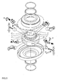
- the four-stroke engine comprises a stationary inner cylinder block 2 and an outer elliptical rim which is composed of two elliptical rim halves 1 and 3 and rotatable around the stationary inner cylinder block 2.
- the cylinder block 2 has a substantially circular shape and includes four cylinders 28 which are arranged in an X-shape so that each cylinder 28 is radially directed from the inner side toward the outside of the cylinder block 2 and is opened on the outer circumference of the cylinder block 2.
- the cylinders 28 each include reciprocating pistons 8 which are arranged to face each other, i.e.
- each piston 8 has two diametral holes 39 and is pivotally connected to the one end of a connecting rod 9 by means of a piston pin 23 inserted through the holes 39 of the piston 8 so that the connecting rod 9 is directed radially outwardly and carries out a translatory motion when the piston 8 is moved up and down.
- the other end of the connecting rod 9 has a bearing pin 11 extending through the connecting rod 9 from both sides thereof, and is pivotally connected to a guiding arm 10 by means of a pin 21 which is inserted into two opposite holes 37 of the guiding arm 10 and another hole of the connecting rod 9.
- the guiding arm 10 is angled in a direction opposite to the connecting rod 9 so as to have an L-shape, wherein the one leg of the guiding arm 10 which is pivotally connected to the connecting rod 9 is longer than the other leg thereof.
- Four longitudinal grooves 25 are formed in the outer circumference of the cylinder block 2 in proximity of the respective openings of the cylinders 28.
- the free end of the shorter leg of the guiding arm 10 has a hole 38 and is inserted into the respective groove 25, wherein a pin 34 is inserted from the rear side of the cylinder block 2 through the hole 38 of the guiding arm 10 to pivotally connect the guiding arm 10 to the cylinder block 2 within the groove 25.
- Two circular push bearings 12 are rotatably arranged on both ends of the bearing pin 11 so as to rotate about a common axis.
- two circular pull bearings 13 having a smaller diameter than that of the push bearings 12 are rotatably arranged on the both ends of the bearing pin 11 at the outer side of both push bearings 12 so that the push and pull bearings 12 and 13 are mounted on the same common axis.
- the assembly of the piston, the connecting rod 9, the guiding arm 10, and the push and pull bearings 12 and 13 as a whole forms a piston set 29, wherein four piston sets 29 are installed at the cylinder block 2 in angles of 90° around the axis thereof.
- a circular front bearing assembly 26 extends from the front side of the cylinder block 2 and has four intake valve openings 49 and four exhaust valve openings 50 which are radially formed in pairs on an outer circumference of the front bearing assembly 26, wherein each pair of intake and exhaust valve openings 49 and 50 is associated to a respective cylinder 28.
- Valve cases 15 are embedded into the intake and exhaust valve openings 49 and 50 and receive respective intake and exhaust valves 14 for opening and closing intake and exhaust openings of a combustion chamber of the respective cylinder 28 to control the supply of air/fuel-mixture in the induction stroke of the piston 8 and the discharge of exhaust gas in the exhaust stroke of the piston 8, respectively.
- rocker fixtures 45 are formed on the outer circumference of the front bearing assembly 26 between the pairs of intake and exhaust valve openings 49 and 50.
- Two arcuated rocker arms 18 are pivotally mounted with their one ends on both ends of each rocker fixture 45 in a direction to the intake and exhaust valves 14.
- a circular cam bearing 19 is rotatably mounted in a middle portion of each rocker arm 18.
- the other ends of the rocker arms 18 are provided with a valve adjuster 20 and engaged with the intake and exhaust valves 14, respectively, by means of a valve spring 16 and a valve spring lock washer 17.
- valve cases 15, the intake and exhaust valves 14, the rocker arm 18, the cam bearing 19, the valve adjuster 20, the valve spring 16, and the valve spring lock washer 17 as a whole forms avalve set 30, wherein eight valve sets 30 are installed at the cylinder block 2 in correspondence with the respective inlet and outlet valve openings 49 and 50.
- the front side of the front bearing assembly 26 comprises a plurality of coolant inlet and outlet ports 42 and 43 for supplying and discharging coolant and circulating the coolant within the cylinder block 2, a plurality of mixture intake passages 40 for supplying air/fuel-mixture into the cylinders 28, and a plurality of spark plug cable openings 47 for passing spark splug cables, which all are formed in a circumferential direction, wherein the mixture intake passages 40 have a larger diameter than that of the coolant inlet and outlet ports 42 and the spark plug cable openings 47.
- an exhaust passage 41 is formed on the center of the front side of the front bearing assembly 26 for discharging exhaus gas from the cylinders 28, with the diameter of the exhaust passage 41 being larger than the diameter of all the other apertures.
- the front side of the front bearing assembly 26 also comprises a plurality of fixing elements 48 for fixing the cylinder block 2 to a body on which the engine is to be used.
- a plurality of pressure relief passages 44 and 46 are formed on the outer circumference and the front side of the front bearing assembly 26 for controlling intake pressure.
- a circular rear bearing assembly 27 extends from the rear side of the cylinder block 2 and has four spark plug openings 36 which are formed on an inner side of the rear bearing assembly 27.
- Four spark plugs 22 are mounted in the spark plug openings 36 and are associated to the respective cylinders 28.
- a plurality of spark plug cable openings 33 are formed on the rear side of the rear bearing assembly 27, so that the spark plug cables can be passed through the spark plug cable openings 33 and 47 of the front and rear bearing assembly 26 and 27 to the respective spark plugs 22.
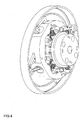
- the outer elliptical rim is composed of two elliptical rim halves, i.e. a front elliptical rim half 3 and a rear elliptical rim half 1, which are rotatably supported by the front and rear bearing assemblies 26 and 27, respectively, and connected to each other by fastening means (not shown) inserted into jointing holes 35 formed in the circumferential edges of the front and rear elliptical rim halves 3 and 1.
- the rear elliptical rim half 1 has an inner circumferential surface for contacting the push bearings 12 of the connecting rods 9, and the front and rear elliptical rim halves 3 and 1 each have an inner elliptical guide 6 for contacting the pull bearings 13 of the connecting rods 9. Therefore, the push and pull bearings 12 and 13 of the connecting rods 9 are guided along the inner circumferential surface and the inner elliptical guide 6 of the elliptical rim in contact therewith, so that the elliptical rim acts like a crankshaft of the engine.
- the inner circumference of the front elliptical rim half 3 is provided with a plurality of cam teeth 7 which engage with the cam bearings 19 of the rocker arms 18 to control and synchronize the opening and closing operation of the intake and exhaust valves 14, so that the cam teeth 7 act like a camshaft of the engine.
- the front side of the front elliptical rim half 3 is provided with a bearing 4 and an oil ring 5 for supporting and sealing the elliptical rim on the front bearing assembly 26.
- the circumference of the rear elliptical rim half 1 is provided with through holes 24 for entering and exiting oil, so that the rotating part of the engine, such as the inner circmferential surface and the inner elliptical guide 6 of the elliptical rim, the push and pull bearings 12 and 13 of the connecting rods 9, and the pistons 8 of the cylinders 28, can be securely lubricated.
- the rear side of the rear elliptical rim half 1 is provided with a bearing and an oil ring for supporting and sealing the elliptical rim on the rear bearing assembly 27.
- the rear side of the rear elliptical rim half 1 has a flywheel attachment surface 31 including a plurality of bolt holes 32 for attaching a flywheel by means of fastening means (not shown).
- the rear elliptical rim half 1 is further coupled to an output shaft (not shown).
- Fig. 4 shows the cylinder block 2 having the grooves 25 in which the angled guiding arms 10 are mounted, as described above.
- the cylinder block 2 has tabs which extend from the outer circumference of the cylinder block 2, and straigt guiding arms which are pivotally connected to the tabs and the connecting rods 9.
- the four pistons 8 are successive positioned to operate in their four strokes, i.e. position 1 indicates the compression stroke, position 2 indicates the power stroke, position 3 indicates the exhaust stroke, and position 4 indicates the induction stroke.
- the piston 8 which operates in the power stroke, as indicated by position 2 pushes the push bearings 12 of the connecting rod 9 outwardly against the inner circumferential surface of the elliptical rim by the volume expansion.
- the connecting rod 9 is supported by the guiding arm 10 which is pivotally connected to the cylinder block 2 and generates a counter force against the pushing force of the connecting rod 9, so that the connecting rod 9 outwardly pushes to pivot in a clockwise direction, and the push bearings 12 rotate in a counterclockwise direction along the inner circumferential surface of the elliptical rim about the point of the long axis of the elliptical rim due to the contact between the push bearings 12 and the inner circumferential surface of the elliptical rim. As a consequence, the elliptical rim is rotated in the counterclockwise direction to drive the output shaft.
- the subsequent piston 8 is operated in the exhaust stroke, as shown by position 3 in fig. 1 , in which the push bearings 12 are rotated along the inner circumference surface of the elliptical rim about the point of the short axis of the elliptical rim, so that the connecting rod 9 is inwardly pushed to discharge the exhaust gases through the opened exhaust valve 50.
- the subsequent piston 8 is operated in the induction stroke in which the pull bearings 13 are rotated along the inner elliptical guide 6 of the elliptical rim about the point of the long axis of the elliptical rim, so that the connecting rod 9 is outwardly pulled to supply the air/fuel-mixture through the opened intake valve 49.
- the subsequent piston 8 is operated in the compression stroke in which the push bearings 12 are rotated along the inner circumference surface of the elliptical rim about the point of the short axis of the elliptical rim, so that the connecting rod 9 is inwardly pushed to compress the air/fuel-mixture while the intake and exhaust valves 49 and 50 are closed.
- the power stroke, the exhaust stroke, the induction stroke, and the compression stroke are synchronously performed by the four pistons 8, so that each of the four pistons 8 completes the full cycle in one revolution of the elliptical rim, i.e. each piston 8 performs a power stroke per revolution of the elliptical rim. Therefore, four power strokes per revolution of the elliptical rim are continuously performed, so that the power efficiency of the engine is remarkably increased.
Landscapes
- Engineering & Computer Science (AREA)
- Mechanical Engineering (AREA)
- General Engineering & Computer Science (AREA)
- Chemical & Material Sciences (AREA)
- Combustion & Propulsion (AREA)
- Physics & Mathematics (AREA)
- Geometry (AREA)
- Valve-Gear Or Valve Arrangements (AREA)
- Transmission Devices (AREA)
- Lubrication Of Internal Combustion Engines (AREA)
- Pistons, Piston Rings, And Cylinders (AREA)
- Cylinder Crankcases Of Internal Combustion Engines (AREA)
Applications Claiming Priority (1)
| Application Number | Priority Date | Filing Date | Title |
|---|---|---|---|
| US11/891,662 US20090038565A1 (en) | 2007-08-09 | 2007-08-09 | Continuous Otto piston elliptical engine |
Publications (2)
| Publication Number | Publication Date |
|---|---|
| EP2022960A2 true EP2022960A2 (de) | 2009-02-11 |
| EP2022960A3 EP2022960A3 (de) | 2010-04-07 |
Family
ID=39926552
Family Applications (1)
| Application Number | Title | Priority Date | Filing Date |
|---|---|---|---|
| EP07122874A Withdrawn EP2022960A3 (de) | 2007-08-09 | 2007-12-11 | Viertaktmotor |
Country Status (7)
| Country | Link |
|---|---|
| US (1) | US20090038565A1 (de) |
| EP (1) | EP2022960A3 (de) |
| KR (1) | KR20090015774A (de) |
| AR (1) | AR067893A1 (de) |
| BR (1) | BRPI0805069A2 (de) |
| MX (1) | MX2008010214A (de) |
| SG (1) | SG151156A1 (de) |
Cited By (2)
| Publication number | Priority date | Publication date | Assignee | Title |
|---|---|---|---|---|
| EA024495B1 (ru) * | 2009-10-06 | 2016-09-30 | Рамзан Усманович Гойтемиров | Двухроторная гибридная установка |
| CN110454280A (zh) * | 2018-05-07 | 2019-11-15 | 刘念慈 | 回转式引擎的燃烧室 |
Families Citing this family (4)
| Publication number | Priority date | Publication date | Assignee | Title |
|---|---|---|---|---|
| US7610894B2 (en) * | 2005-05-16 | 2009-11-03 | Fsnc, Llc | Self-compensating cylinder system in a process cycle |
| CN105927374B (zh) * | 2016-06-24 | 2018-08-17 | 庞锦恒 | 旋转气缸活塞式转子发动机 |
| US10041592B2 (en) * | 2016-09-01 | 2018-08-07 | Western Distributing Company | Interlocking piston button |
| CN114060144B (zh) * | 2020-11-05 | 2024-04-09 | 廖平阳 | 一种内燃机 |
Family Cites Families (8)
| Publication number | Priority date | Publication date | Assignee | Title |
|---|---|---|---|---|
| GB191215176A (en) * | 1912-06-28 | 1913-04-24 | John Kellington | Fluid Pressure Engine. |
| US1589983A (en) * | 1922-09-18 | 1926-06-22 | Isaac S Gellert | Single-sleeve valve for internal-combustion engines |
| US1826325A (en) * | 1930-09-02 | 1931-10-06 | William F Paul | Wobble wheel power transmission |
| US2941521A (en) * | 1958-07-21 | 1960-06-21 | Chrysler Corp | Engine head |
| DE3306352A1 (de) * | 1983-02-24 | 1983-11-24 | Hans 8621 Weidhausen Kugelberg | 4 takt-motor mit zentralverbrennung u. symmetr. kraftverlauf |
| FR2554506B1 (fr) * | 1983-11-08 | 1988-05-13 | Duboeuf Louis | Moteur a combustion interne a piston a mouvement alternatif |
| US6279518B1 (en) * | 2000-03-03 | 2001-08-28 | Johnny L. Cooley | Rotary engine having a conical rotor |
| WO2007090248A1 (en) * | 2006-07-07 | 2007-08-16 | Ramzan Usmanovich Goytemirov | Internal combustion engine |
-
2007
- 2007-08-09 US US11/891,662 patent/US20090038565A1/en not_active Abandoned
- 2007-11-07 KR KR1020070113043A patent/KR20090015774A/ko not_active Withdrawn
- 2007-12-11 EP EP07122874A patent/EP2022960A3/de not_active Withdrawn
-
2008
- 2008-05-15 SG SG200803720-2A patent/SG151156A1/en unknown
- 2008-08-07 BR BRPI0805069-4A patent/BRPI0805069A2/pt not_active IP Right Cessation
- 2008-08-08 MX MX2008010214A patent/MX2008010214A/es not_active Application Discontinuation
- 2008-08-08 AR ARP080103482A patent/AR067893A1/es unknown
Cited By (2)
| Publication number | Priority date | Publication date | Assignee | Title |
|---|---|---|---|---|
| EA024495B1 (ru) * | 2009-10-06 | 2016-09-30 | Рамзан Усманович Гойтемиров | Двухроторная гибридная установка |
| CN110454280A (zh) * | 2018-05-07 | 2019-11-15 | 刘念慈 | 回转式引擎的燃烧室 |
Also Published As
| Publication number | Publication date |
|---|---|
| BRPI0805069A2 (pt) | 2009-07-21 |
| SG151156A1 (en) | 2009-04-30 |
| KR20090015774A (ko) | 2009-02-12 |
| US20090038565A1 (en) | 2009-02-12 |
| MX2008010214A (es) | 2009-03-05 |
| AR067893A1 (es) | 2009-10-28 |
| EP2022960A3 (de) | 2010-04-07 |
Similar Documents
| Publication | Publication Date | Title |
|---|---|---|
| KR100772974B1 (ko) | 엔진 발전기 | |
| CA2468169C (en) | Internal combustion engine | |
| EP1952001B1 (de) | Verbrennungsmotor | |
| JP3016485B2 (ja) | クランク無し往復運動2サイクル内燃機関 | |
| KR100490247B1 (ko) | 개선된 축 피스톤 로터리 엔진 | |
| AU686204B2 (en) | Dwelling scotch yoke engine | |
| US11725576B2 (en) | Internal combustion engine with adaptable piston stroke | |
| EP2022960A2 (de) | Viertaktmotor | |
| HU219044B (hu) | Axiáldugattyús forgógép | |
| KR0144452B1 (ko) | 회전식 슬리이브밸브 내연기관 | |
| JP2010190223A (ja) | 往復機関 | |
| US20130228150A1 (en) | Rotary, Internal Combustion Engine | |
| CA2638428A1 (en) | Continuous otto piston elliptical engine | |
| US7210446B2 (en) | V-twin configuration having rotary mechanical field assembly | |
| US7520251B2 (en) | Non-reciprocating internal combustion engine | |
| TWI850778B (zh) | 二行程燃油引擎之改良 | |
| US7188598B2 (en) | Rotary mechanical field assembly | |
| CN224049299U (zh) | 一种单缸二冲程凸轮活塞发动机 | |
| KR20090055707A (ko) | 세기 엔진 | |
| US20050061269A1 (en) | Stotler variable displacement radial rotary piston engine | |
| RU2333372C2 (ru) | Роторный двигатель карфидова | |
| JP2009047065A (ja) | オットサイクルで連続作動するピストンを有する楕円形エンジン | |
| JPH10339158A (ja) | ロータリー式内燃機関 | |
| JPH02301607A (ja) | 回転式スリーブバルブ内燃機関 |
Legal Events
| Date | Code | Title | Description |
|---|---|---|---|
| PUAI | Public reference made under article 153(3) epc to a published international application that has entered the european phase |
Free format text: ORIGINAL CODE: 0009012 |
|
| AK | Designated contracting states |
Kind code of ref document: A2 Designated state(s): AT BE BG CH CY CZ DE DK EE ES FI FR GB GR HU IE IS IT LI LT LU LV MC MT NL PL PT RO SE SI SK TR |
|
| AX | Request for extension of the european patent |
Extension state: AL BA HR MK RS |
|
| PUAL | Search report despatched |
Free format text: ORIGINAL CODE: 0009013 |
|
| AK | Designated contracting states |
Kind code of ref document: A3 Designated state(s): AT BE BG CH CY CZ DE DK EE ES FI FR GB GR HU IE IS IT LI LT LU LV MC MT NL PL PT RO SE SI SK TR |
|
| AX | Request for extension of the european patent |
Extension state: AL BA HR MK RS |
|
| 17P | Request for examination filed |
Effective date: 20101007 |
|
| 17Q | First examination report despatched |
Effective date: 20101109 |
|
| AKX | Designation fees paid |
Designated state(s): DE TR |
|
| GRAP | Despatch of communication of intention to grant a patent |
Free format text: ORIGINAL CODE: EPIDOSNIGR1 |
|
| STAA | Information on the status of an ep patent application or granted ep patent |
Free format text: STATUS: THE APPLICATION IS DEEMED TO BE WITHDRAWN |
|
| 18D | Application deemed to be withdrawn |
Effective date: 20121228 |