EP2022977A1 - Druckausgeglichenes Servoventil für ein Brennstoffeinspritzventil einer Verbrennungskraftmaschine - Google Patents
Druckausgeglichenes Servoventil für ein Brennstoffeinspritzventil einer Verbrennungskraftmaschine Download PDFInfo
- Publication number
- EP2022977A1 EP2022977A1 EP07425480A EP07425480A EP2022977A1 EP 2022977 A1 EP2022977 A1 EP 2022977A1 EP 07425480 A EP07425480 A EP 07425480A EP 07425480 A EP07425480 A EP 07425480A EP 2022977 A1 EP2022977 A1 EP 2022977A1
- Authority
- EP
- European Patent Office
- Prior art keywords
- sleeve
- end portion
- servovalve
- outlet channel
- axial
- Prior art date
- Legal status (The legal status is an assumption and is not a legal conclusion. Google has not performed a legal analysis and makes no representation as to the accuracy of the status listed.)
- Granted
Links
Images


Classifications
-
- F—MECHANICAL ENGINEERING; LIGHTING; HEATING; WEAPONS; BLASTING
- F02—COMBUSTION ENGINES; HOT-GAS OR COMBUSTION-PRODUCT ENGINE PLANTS
- F02M—SUPPLYING COMBUSTION ENGINES IN GENERAL WITH COMBUSTIBLE MIXTURES OR CONSTITUENTS THEREOF
- F02M59/00—Pumps specially adapted for fuel-injection and not provided for in groups F02M39/00 -F02M57/00, e.g. rotary cylinder-block type of pumps
- F02M59/44—Details, components parts, or accessories not provided for in, or of interest apart from, the apparatus of groups F02M59/02 - F02M59/42; Pumps having transducers, e.g. to measure displacement of pump rack or piston
- F02M59/46—Valves
-
- F—MECHANICAL ENGINEERING; LIGHTING; HEATING; WEAPONS; BLASTING
- F02—COMBUSTION ENGINES; HOT-GAS OR COMBUSTION-PRODUCT ENGINE PLANTS
- F02M—SUPPLYING COMBUSTION ENGINES IN GENERAL WITH COMBUSTIBLE MIXTURES OR CONSTITUENTS THEREOF
- F02M63/00—Other fuel-injection apparatus having pertinent characteristics not provided for in groups F02M39/00 - F02M57/00 or F02M67/00; Details, component parts, or accessories of fuel-injection apparatus, not provided for in, or of interest apart from, the apparatus of groups F02M39/00 - F02M61/00 or F02M67/00; Combination of fuel pump with other devices, e.g. lubricating oil pump
- F02M63/0012—Valves
- F02M63/0031—Valves characterized by the type of valves, e.g. special valve member details, valve seat details, valve housing details
- F02M63/004—Sliding valves, e.g. spool valves, i.e. whereby the closing member has a sliding movement along a seat for opening and closing
-
- F—MECHANICAL ENGINEERING; LIGHTING; HEATING; WEAPONS; BLASTING
- F02—COMBUSTION ENGINES; HOT-GAS OR COMBUSTION-PRODUCT ENGINE PLANTS
- F02M—SUPPLYING COMBUSTION ENGINES IN GENERAL WITH COMBUSTIBLE MIXTURES OR CONSTITUENTS THEREOF
- F02M47/00—Fuel-injection apparatus operated cyclically with fuel-injection valves actuated by fluid pressure
- F02M47/02—Fuel-injection apparatus operated cyclically with fuel-injection valves actuated by fluid pressure of accumulator-injector type, i.e. having fuel pressure of accumulator tending to open, and fuel pressure in other chamber tending to close, injection valves and having means for periodically releasing that closing pressure
- F02M47/027—Electrically actuated valves draining the chamber to release the closing pressure
-
- F—MECHANICAL ENGINEERING; LIGHTING; HEATING; WEAPONS; BLASTING
- F02—COMBUSTION ENGINES; HOT-GAS OR COMBUSTION-PRODUCT ENGINE PLANTS
- F02M—SUPPLYING COMBUSTION ENGINES IN GENERAL WITH COMBUSTIBLE MIXTURES OR CONSTITUENTS THEREOF
- F02M61/00—Fuel-injectors not provided for in groups F02M39/00 - F02M57/00 or F02M67/00
- F02M61/04—Fuel-injectors not provided for in groups F02M39/00 - F02M57/00 or F02M67/00 having valves, e.g. having a plurality of valves in series
-
- F—MECHANICAL ENGINEERING; LIGHTING; HEATING; WEAPONS; BLASTING
- F02—COMBUSTION ENGINES; HOT-GAS OR COMBUSTION-PRODUCT ENGINE PLANTS
- F02M—SUPPLYING COMBUSTION ENGINES IN GENERAL WITH COMBUSTIBLE MIXTURES OR CONSTITUENTS THEREOF
- F02M63/00—Other fuel-injection apparatus having pertinent characteristics not provided for in groups F02M39/00 - F02M57/00 or F02M67/00; Details, component parts, or accessories of fuel-injection apparatus, not provided for in, or of interest apart from, the apparatus of groups F02M39/00 - F02M61/00 or F02M67/00; Combination of fuel pump with other devices, e.g. lubricating oil pump
- F02M63/0012—Valves
- F02M63/0014—Valves characterised by the valve actuating means
- F02M63/0015—Valves characterised by the valve actuating means electrical, e.g. using solenoid
-
- F—MECHANICAL ENGINEERING; LIGHTING; HEATING; WEAPONS; BLASTING
- F02—COMBUSTION ENGINES; HOT-GAS OR COMBUSTION-PRODUCT ENGINE PLANTS
- F02M—SUPPLYING COMBUSTION ENGINES IN GENERAL WITH COMBUSTIBLE MIXTURES OR CONSTITUENTS THEREOF
- F02M63/00—Other fuel-injection apparatus having pertinent characteristics not provided for in groups F02M39/00 - F02M57/00 or F02M67/00; Details, component parts, or accessories of fuel-injection apparatus, not provided for in, or of interest apart from, the apparatus of groups F02M39/00 - F02M61/00 or F02M67/00; Combination of fuel pump with other devices, e.g. lubricating oil pump
- F02M63/0012—Valves
- F02M63/0031—Valves characterized by the type of valves, e.g. special valve member details, valve seat details, valve housing details
- F02M63/0043—Two-way valves
-
- F—MECHANICAL ENGINEERING; LIGHTING; HEATING; WEAPONS; BLASTING
- F02—COMBUSTION ENGINES; HOT-GAS OR COMBUSTION-PRODUCT ENGINE PLANTS
- F02M—SUPPLYING COMBUSTION ENGINES IN GENERAL WITH COMBUSTIBLE MIXTURES OR CONSTITUENTS THEREOF
- F02M63/00—Other fuel-injection apparatus having pertinent characteristics not provided for in groups F02M39/00 - F02M57/00 or F02M67/00; Details, component parts, or accessories of fuel-injection apparatus, not provided for in, or of interest apart from, the apparatus of groups F02M39/00 - F02M61/00 or F02M67/00; Combination of fuel pump with other devices, e.g. lubricating oil pump
- F02M63/0012—Valves
- F02M63/007—Details not provided for in, or of interest apart from, the apparatus of the groups F02M63/0014 - F02M63/0059
- F02M63/0078—Valve member details, e.g. special shape, hollow or fuel passages in the valve member
- F02M63/008—Hollow valve members, e.g. members internally guided
-
- F—MECHANICAL ENGINEERING; LIGHTING; HEATING; WEAPONS; BLASTING
- F02—COMBUSTION ENGINES; HOT-GAS OR COMBUSTION-PRODUCT ENGINE PLANTS
- F02M—SUPPLYING COMBUSTION ENGINES IN GENERAL WITH COMBUSTIBLE MIXTURES OR CONSTITUENTS THEREOF
- F02M2200/00—Details of fuel-injection apparatus, not otherwise provided for
- F02M2200/16—Sealing of fuel injection apparatus not otherwise provided for
-
- F—MECHANICAL ENGINEERING; LIGHTING; HEATING; WEAPONS; BLASTING
- F02—COMBUSTION ENGINES; HOT-GAS OR COMBUSTION-PRODUCT ENGINE PLANTS
- F02M—SUPPLYING COMBUSTION ENGINES IN GENERAL WITH COMBUSTIBLE MIXTURES OR CONSTITUENTS THEREOF
- F02M2200/00—Details of fuel-injection apparatus, not otherwise provided for
- F02M2200/26—Fuel-injection apparatus with elastically deformable elements other than coil springs
-
- F—MECHANICAL ENGINEERING; LIGHTING; HEATING; WEAPONS; BLASTING
- F02—COMBUSTION ENGINES; HOT-GAS OR COMBUSTION-PRODUCT ENGINE PLANTS
- F02M—SUPPLYING COMBUSTION ENGINES IN GENERAL WITH COMBUSTIBLE MIXTURES OR CONSTITUENTS THEREOF
- F02M2547/00—Special features for fuel-injection valves actuated by fluid pressure
- F02M2547/003—Valve inserts containing control chamber and valve piston
Definitions
- the present invention concerns a balanced metering servovalve for a fuel injector of an internal combustion engine.
- the metering servovalve comprises a control chamber, which communicates with a fuel inlet and with an outlet channel having a calibrated portion.
- the pressure in the control chamber controls the axial sliding of the rod, for the purpose of opening and closing the nozzle, and is adjusted by controlling an actuator comprising an electromagnet and a spring.
- the actuator operates the translation of a sleeve between a closed position and an open position of the outlet channel.
- the sleeve is mounted so that it can slide in a substantially fluid-tight manner on an axial stem, which forms part of a fixed valve body with respect to the casing.
- the outer lateral surface of the axial stem defines an annular chamber into which the outlet channel exits.
- the sleeve closes the annular chamber in such a way as to be subjected to an axial fuel-pressure resultant that, at least in theory, is null.
- the pressure of the fuel in the annular chamber reaches relatively high levels, around 1600-1800 bar for example, when the sleeve is in the closed position, while in the discharge area, or rather downstream of the sealing zone, pressure levels are relatively low, around a few bar. Therefore, the pressure in the annular chamber generates a radial force on the sleeve that is outwardly directed and that deforms the sleeve.
- This deformation has the effect of "widening" the end of the sleeve and consequently increasing the diameter where contact and sealing on the valve body takes place, with respect to the inner diameter of the sleeve in the non-deformed state.
- the contact zone between the sleeve and the valve body is not exactly defined by a circumference, but by an annulus, even if of relatively small radial width. Sealing does not take place in correspondence to the inner diameter of this annulus, but in correspondence to a mean diameter, which is obviously greater than the inner diameter of the sleeve.
- the increase in the diameter where sealing takes place with respect to the inner diameter of sleeve in the non-deformed state has the effect of creating a radial unbalancing force, which acts on the sleeve in the direction corresponding to its opening.
- the magnitude of the radial unbalancing force depends on the fuel supply pressure and the annulus-shaped area defined by the difference between the diameter in which sealing effectively takes place and the minimum inner diameter of the sleeve at the opposite end.
- the actuator spring In order to compensate for the radial unbalancing force, the actuator spring must have a greater preload force with respect to that theoretically determined by design with a perfectly balanced sleeve, from the axial pressure standpoint, to keep the sleeve closed.
- the spring's larger preload forces result in larger accelerations and faster impact speeds on closure against the valve body and, in consequence, greater risks of wear and damage to the metering servovalve.
- the sleeve and the valve body are made using materials with high hardness levels.
- the geometry and the material chosen for the end of the sleeve are such as to provide the sleeve with high rigidity, so as to practically eliminate elastic deformations.
- the geometry chosen to increase the rigidity results in an increase of the mass of the sleeve and therefore the amount of contact momentum with the valve body during closure. In consequence, the sleeve is subjected to undesired rebounding against the valve body during closure.
- the metering servovalve does not close immediately, resulting in a greater quantity of fuel being injected into the cylinder than that determined by design.
- the object of the present invention is that of providing a balanced metering servovalve for a fuel injector of an internal combustion engine that allows the above-indicated problems to be resolved in a simple and economic manner.
- a metering servovalve for a fuel injector of an internal combustion engine comprising:
- said electro-actuator comprises a spring having a predefined preload to axially push said sleeve towards said closed position, and the geometry of said end portion is such that said radial unbalancing force exceeds the thrust of said preload when the supply pressure of said fuel exceeds a safety threshold.
- the ratio between the outer and inner diameters of said end portion is less than 2.4.
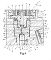
- reference numeral 1 indicates, in its entirety, a fuel injector (partially shown) for an internal combustion engine, in particular a diesel-cycle one.
- the injector 1 comprises a hollow body or casing 2, commonly called the “injector body", which extends along a longitudinal axis 3, and has a side inlet 4 that can be connected to a high-pressure fuel supply line, at a pressure of around 1600 bar for example.
- the casing 2 terminates in an injection nozzle (not visible the figure), which is in communication with the inlet 4, through a channel 4a, and is able to inject fuel into an associated cylinder of the engine.
- the casing 2 defines an axial cavity 6 in which a metering servovalve 5 is housed and another cavity coaxial with cavity 6 and housing an actuator 15, which comprises an electromagnet 16 and a notched-disc anchor 17 controlled by the electromagnet 16.
- the anchor 17 is fixed with respect to a sleeve 18, which extends along axis 3.
- the electromagnet 16 comprises a magnetic core 19, which has a surface 20 perpendicular to axis 3 and defines an axial stop for the anchor 17, and is held in position by a support 21.
- the actuator 15 ha an axial cavity 22 housing a coil compression spring 23, which is preloaded to exert thrust on the anchor 17 in the opposite axial direction to the attraction exerted by the electromagnet 16.
- the spring 23 has one end resting against an internal shoulder of the support 21 (not shown) and the other end acting on the anchor 17.
- the metering servovalve 5 comprises a valve body, made in three pieces: a tubular body 75 (partially shown), a disc 33b and a distribution and guide body 76.
- Body 75 defines an axial through hole 9, in which a control rod 10 axially slides, in a fluid-tight manner, to control a shutter needle, in the known manner and not shown, which opens and closes the injection nozzle.
- One axial end of the body 75 has an external flange 33a housed in a portion 34 of the cavity 6 of increased diameter and arranged in axial contact against a shoulder 35 inside the cavity 6.
- One end of the hole 9 defines a control chamber 26, which is in permanent communication with the inlet 4, through a channel 28 made in the body 75, to receive pressurized fuel.
- the channel 28 comprises a calibrated portion 29 and exits, with one end, into the control chamber 26 and, with the other end, into an annular chamber 30, defined by an outer cylindrical surface 11 of the body 75 and an annular groove on the inner surface of the cavity 6.
- a channel 32 made in body 2 and in communication with the inlet 4 exits into the annular chamber 30.
- the control chamber 26 is axially delimited on one side by an end surface 25 of the rod 10, usefully having a truncated-cone shape and, on the other, by a bottom surface 27, which constitutes part of the face of the disc 33b.
- the disc 33b is arranged in axial contact against the flange 33a on one side and against a surface 77 of body 76 on the other.
- the surface 77 axially delimits a base of the body 75 having an external flange 33c.
- the disc 33b is axially secured in a fixed and fluid-tight position between the flanges 33a and 33c via a threaded ring nut 36, which makes contact with the flange 33c and is screwed into an internal thread 37 of portion 34.
- the body 76 also comprises a guide element for the anchor 17 and the sleeve 18. This element is defined by a substantially cylindrical stem 38 having a smaller diameter than that of the flange 33c.
- the stem 38 projects beyond the base of body 76 along axis 3 in the opposite direction from disc 33b and body 75, i.e. towards the cavity 22.
- the stem 38 is externally delimited by a lateral cylindrical surface 39, which guides the axial sliding of the sleeve 18.
- the sleeve 18 has an internal cylindrical surface 40, coupled to the lateral surface 39 of the stem 38 in a substantially fluid-tight manner, i.e. via a coupling with opportune diameter clearance, less than 4 micron for example, or via the insertion of specific sealing elements.
- the control chamber 26 is in permanent communication with a fuel outlet channel, indicated as a whole by reference numeral 42.
- the channel 42 comprises an axial segment 43, which is made in the body 76 (partly in the flange 33c and partly in the stem 38) and, in turn, comprises an inlet 63 and a blind end 66 ( Figure 2 ), which has a smaller diameter than that of the inlet 63 and extends beyond the flange 33c into the stem 38.
- the channel 42 also comprises an outlet segment 44, which is radial and exits, at one end, into the end 66 of segment 43 and, at the other end, into a chamber 46 defined by an annular groove in the lateral surface 39 of the stem 38.
- the chamber 46 is obtained in an axial position next to the flange 33c and is opened/closed by an end portion 47 of the sleeve 18, which defines a shutter for the channel 42.
- the portion 47 terminates with an internal truncated-cone surface united to the surface 40 via an edge 48, which is provided for resting against a truncated-cone connecting surface 49 between the flange 33c and the stem 38, to define a circular sealing zone.
- the sleeve 18 slides on the stem 38, together with the anchor 17, between an advanced end stop, or closed position, and a retracted end stop, or open position.
- the portion 47 closes the chamber 46 and thus the outlet of segments 44 of the channel 42.
- portion 47 sufficiently opens the chamber 46 to allow segments 44 to discharge the fuel in the control chamber 26 through channel 42 and chamber 46.
- the passage section left open by portion 47 has a truncated-cone shape and is at least three times larger that the passage section of a single segment 44.
- the advanced end stop position of the sleeve 18 is defined by the edge 48 hitting against the connection surface 49 between the flange 33 and the stem 38.
- the retracted end stop position of the sleeve 18 is defined by the anchor 17 axially hitting against the surface 20 of the core 19, with a nonmagnetic gap sheet 51 inserted in between.
- the chamber 46 is placed in communication with a discharge channel of the injector (not shown) via an annular passage between the ring nut 36 and the sleeve 18, the notches in the anchor 17, the cavity 22 and an opening in the support 21.
- the anchor 17, together with the sleeve 18, moves towards the core 19 and hence portion 47 opens the chamber 46.
- the fuel is then discharged from the control chamber 26: in this way, the fuel pressure in the control chamber 26 drops, causing an axial movement of the rod 10 towards the bottom surface 27 and thus the opening of the injection nozzle.
- the spring 23 moves the anchor 17, together with the sleeve 18, to the advanced end stop position.
- the chamber 46 is closed and the pressurized fuel entering from the channel 28 re-establishes high pressure in the control chamber 26, resulting in the rod 10 moving away from the bottom surface 27 and operating the closure of the injection nozzle.
- the fuel exerts an almost null axial thrust resultant on the sleeve 18, as the pressure in the chamber 46 only acts radially on the lateral surface 40 of the sleeve 18.
- channel 42 includes one or more calibrated restrictions.
- the term “restriction” is intended as a hole (or, more in general, a segment of the channel 42) with a smaller passage section than that which the fuel flow encounters upstream and downstream of this hole.
- the term “calibrated” is intended as the fact that the passage section is made with precision so as to precisely define a preset fluid outflow from the control chamber 26 and to cause a predetermined pressure drop from upstream to downstream.
- the flow is interrupted: in use, having a pressure upstream of the hole equal to that established during the finishing operation, the final passage section that is obtained defines a pressure drop equal to the difference in pressure established upstream and downstream of the hole during the finishing operation and a fuel flow rate equal to the predetermined design flow rate.
- these calibrated restrictions can be arranged in series with and/or in parallel to each other.
- the calibrated restriction 53 axially extends for only part of the disc 33b and is in a position next to the control chamber 26, while the rest of the disc 33b has an axial segment 43a of larger diameter, of the same order of magnitude as that of the inlet 63 of segment 43.
- the disc 33b could be inverted, in this way having segment 43a exiting directly into the end of the hole 9, adding to the volume of the control chamber 26.
- the calibrated restriction 53 has a diameter between 150 and 300 micron.
- the diameter of the blind end 66 is greater than that of the calibrated restriction 53: for example, it can be approximately twice that of the calibrated restriction 53.
- the diameter of blind end 66 is still relatively small, the diameter of the stem 38 and thus the diameter of the edge 48 where the seal is formed can be restrained, for example, to a value between 2.5 and 3.5 mm, depending on the materials chosen and the type of heat treatment adopted.
- the pressure drop that occurs between the control chamber 26 and the discharge zone when portion 47 is in the open position is divided into as many pressure drops as there are calibrated restrictions arranged in series along the channel 42.
- three calibrated restrictions are arranged in series, and/or the disc 33b is absent, and/or the disc 33b and the body 75 constitute part of an element made as a single piece, and/or one of the calibrated restrictions is made in an insert embedded in the inlet 63 of the body 76 or the disc 33b.
- segment 43 comprises an axial segment 58 that substitutes the inlet 63 and the calibrated restriction 66 and has a constant diameter of the same order of magnitude as the inlet 63 and segment 43a.
- the outlet segments 44 are substituted by inclined outlet segments 59, which define a calibrated restriction arranged in series with the calibrated restriction 53 and place the chamber 46 in direct communication with the bottom of segment 58.
- segments 59 form an angle on inclination between 30° and 45° with respect to axis 3.
- segment 58 terminate before the beginning of the stem 38, the stem 38 proves to be relatively robust.
- the diameter of the stem 38 and thus the diameter of the annular sealing zone between the sleeve 18 and the stem 38, defined by the edge 48, can be reduced in consequence, with obvious benefits in limiting leaks in this sealing zone under dynamic conditions.
- the diameter of the sealing zone (defined by the edge 48 in the non-deformed state) can be kept at a value between 2.5 and 3.5 mm without the stem 38 appearing structurally weak.
- segment 58 usefully has a diameter between 8 and 20 times that of the calibrated restriction 53, in order to facilitate the intersection of the inclined outlet segments 59 with the bottom of segment 58 during manufacture.
- the geometry of the shutter defined by the portion 47 of the sleeve 18 is such as to render the portion 47 elastically deformable and not rigid as in the known art.
- the ratio between the outer diameter D1 and the inner diameter D2 of portion 47 in the non-deformed state is less than 2.2.
- the ratio between the axial length L and the inner diameter D2 of portion 47 is greater than 1.8.
- the axial length L is intended as running from the edge 48 in which the seal is formed up to a position in which an abrupt change in the outer diameter of the sleeve 18 is encountered: for example, in the solution in Figure 1 , this abrupt change occurs right at the end of the sleeve 18, i.e. in correspondence to the anchor 17.
- the ratio between the outer diameter D1 of the sleeve 18 and the inner diameter D2 is greater than 1.7 and/or the ratio between the axial length L of the sleeve 18 and the inner diameter D2 is less than 3, in order to avoid deformation and/or excessive weakening of the sleeve 18.
- the sleeve 18 comprises an end portion 100, at the opposite end to portion 47, with an outer diameter greater than the outer diameter D1.
- an abrupt enlargement defined by an annular shoulder orthogonal to axis 3 is provided between portions 47 and 100.
- portion 100 has greater rigidity with respect to that of portion 47, for which the elastic deformation is concentrated on portion 47 itself, while portion 100, remaining substantially undeformed, is able to assure the fluid seal between surfaces 39 and 40 in position next to the anchor 17 without the need to add gasket elements.
- a geometry is expressly sought that lets portion 47 of the sleeve 18 elastically deform in a radially outward direction under the effect of the pressure in the chamber 46 when the sleeve 18 is in the closed position.
- the edge 48 is more external with respect to the non-deformed state, for which the seal between portion 47 and surface 49 occurs in correspondence to a mean diameter greater than the theoretical one of the non-deformed state.
- the main effect resides in converting most of the kinetic energy of the sleeve 18 into elastic deformation, at the moment of impact of portion 47 against surface 49. This conversion of kinetic energy into elastic deformation energy has the advantage of a significant reduction in rebound phenomena.
- portion 47 tends to release the accumulated elastic energy to return to the non-deformed state.
- the deformation energy tends to be transformed back into kinetic energy, but the times of this reconversion are relatively long, in particular with respect to known art in which the sleeve 18 is rigid.
- portion 47 on surface 49 reduces possible phenomena of micro-fractures and/or surface micro-welds, which instead tend to be favoured by high specific loads acting on the edge 48 of portion 47.
- portion 47 on surface 49 it is opportune to choose materials and/or surface treatments for the body 76 and the sleeve 18 that reduce the coefficient of friction.
- portion 47 can be determined in a way to have a radial unbalancing force that exceeds the preload thrust of the spring 23 when the fuel supply pressure exceeds a safety threshold, for example, a threshold of 2500 bar.
- the radial unbalancing force overcomes the preload of the spring 23 and causes the automatic opening of the metering servovalve 5 to discharge part of the fuel from the control chamber 26 through channel 42 and the chamber 46 without operating the movement of the rod 10, thereby ensuring that peak pressure does not damage the components of the injector 1.
- the reduction in the diameter of the stem 38 below 3.5 mm, and thus the reduction in the seal diameter of portion 47, allows reductions in leakage under dynamic conditions and the preload required for the spring 23, and thus the force required from the actuator 15.
- the choice of a diameter value below 3.5 mm for the stem 38 is made in function of the material chosen for the valve body, the heat treatment to which the valve body is subjected and consequently its toughness and, lastly, the machining cycle adopted.
- the reduction in seal diameter of portion 47 provides the possibility of also reducing the axial length of the sleeve 18 and therefore to reduce its mass even further.
- the flow rate of fluid leakage between the surfaces 39 and 40 is directly proportional to the length of their circumference in the coupling zone, but inversely proportional to the axial length of this coupling zone: by decreasing the diameter, and thus the length of said circumference, and accepting the same fluid leakage flow rate that a stem with a larger diameter gave, it is possible to reduce the axial length of the coupling zone and, consequently, reduce the mass and overall dimensions.
- the reduction in mass of the sleeve 18 implies a reduction in the response times of the metering servovalve 5.
- the reduction in the outer diameter of the stem 38, and thus the length of seal circumference along the edge 48, reduces the magnitude of the radial unbalancing force and therefore allows the preload force of the spring 23 to be reduced, which must still be provided to compensate the radial unbalancing force due to the elastic deformation of portion 47.
- the ratio between the preload force of the spring 23 and the diameter of the edge 48 is usefully between 10 and 15 [N/mm].
- the reduction in mass of the sleeve 18 also has the effect of reducing rebound phenomena in the closure phase, and therefore better operating precision of the metering servovalve 5.
- the chamber 46 could be at least partially excavated in surface 40 and/or the channel 42 could be asymmetric with respect to axis 3: for example, segments 44 and 59 could have different cross sections from one another, and/or different diameters from one another, and/or have axes lying on the different planes from one another, and/or not all be equally spaced out around the axis 3.
- valve body could be made in two pieces or in a single piece, instead of three pieces, and/or the anchor 17 and the sleeve 18 could be defined by separate elements and arranged in contact against one another, instead of being integrated in a single body.
Landscapes
- Engineering & Computer Science (AREA)
- Chemical & Material Sciences (AREA)
- Combustion & Propulsion (AREA)
- Mechanical Engineering (AREA)
- General Engineering & Computer Science (AREA)
- Physics & Mathematics (AREA)
- Fluid Mechanics (AREA)
- Fuel-Injection Apparatus (AREA)
Priority Applications (7)
| Application Number | Priority Date | Filing Date | Title |
|---|---|---|---|
| EP07425480A EP2022977B1 (de) | 2007-07-30 | 2007-07-30 | Druckausgeglichenes Servoventil für ein Brennstoffeinspritzventil einer Verbrennungskraftmaschine |
| AT07425480T ATE500416T1 (de) | 2007-07-30 | 2007-07-30 | Druckausgeglichenes servoventil für ein brennstoffeinspritzventil einer verbrennungskraftmaschine |
| DE602007012866T DE602007012866D1 (de) | 2007-07-30 | 2007-07-30 | Druckausgeglichenes Servoventil für ein Brennstoffeinspritzventil einer Verbrennungskraftmaschine |
| KR1020080010218A KR100974236B1 (ko) | 2007-07-30 | 2008-01-31 | 내연 기관 엔진의 연료 분사기를 위한 균형 잡힌 계측 서보밸브 |
| US12/023,766 US7954729B2 (en) | 2007-07-30 | 2008-01-31 | Metering servovalve and fuel injector for an internal combustion engine |
| JP2008021196A JP4773467B2 (ja) | 2007-07-30 | 2008-01-31 | 内燃エンジンの燃料噴射装置のための平衡計量サーボバルブ |
| CN2008100089560A CN101358569B (zh) | 2007-07-30 | 2008-01-31 | 用于内燃机的燃料喷射器的平衡计量伺服阀 |
Applications Claiming Priority (1)
| Application Number | Priority Date | Filing Date | Title |
|---|---|---|---|
| EP07425480A EP2022977B1 (de) | 2007-07-30 | 2007-07-30 | Druckausgeglichenes Servoventil für ein Brennstoffeinspritzventil einer Verbrennungskraftmaschine |
Publications (2)
| Publication Number | Publication Date |
|---|---|
| EP2022977A1 true EP2022977A1 (de) | 2009-02-11 |
| EP2022977B1 EP2022977B1 (de) | 2011-03-02 |
Family
ID=38792126
Family Applications (1)
| Application Number | Title | Priority Date | Filing Date |
|---|---|---|---|
| EP07425480A Active EP2022977B1 (de) | 2007-07-30 | 2007-07-30 | Druckausgeglichenes Servoventil für ein Brennstoffeinspritzventil einer Verbrennungskraftmaschine |
Country Status (7)
| Country | Link |
|---|---|
| US (1) | US7954729B2 (de) |
| EP (1) | EP2022977B1 (de) |
| JP (1) | JP4773467B2 (de) |
| KR (1) | KR100974236B1 (de) |
| CN (1) | CN101358569B (de) |
| AT (1) | ATE500416T1 (de) |
| DE (1) | DE602007012866D1 (de) |
Cited By (2)
| Publication number | Priority date | Publication date | Assignee | Title |
|---|---|---|---|---|
| WO2009074427A1 (de) * | 2007-12-10 | 2009-06-18 | Robert Bosch Gmbh | Schaltventil für injektoren |
| US20090320802A1 (en) * | 2008-06-27 | 2009-12-31 | Mario Ricco | Fuel injector provided with a metering servovalve of a balanced type for an internal-combustion engine |
Families Citing this family (7)
| Publication number | Priority date | Publication date | Assignee | Title |
|---|---|---|---|---|
| DE102007009165A1 (de) * | 2007-02-26 | 2008-08-28 | Robert Bosch Gmbh | Kraftstoffinjektor mit einer zusätzlichen Ablaufdrossel oder mit einer verbesserten Anordnung derselben im Steuerventil |
| ATE546636T1 (de) * | 2009-08-26 | 2012-03-15 | Delphi Tech Holding Sarl | Kraftstoffeinspritzdüse |
| EP2405121B1 (de) * | 2010-07-07 | 2013-10-09 | C.R.F. Società Consortile per Azioni | Einspritzanlage für einen Verbrennungsmotor |
| WO2013138805A1 (en) * | 2012-03-16 | 2013-09-19 | International Engine Intellectual Property Company, Llc | Fuel injector needle sleeve |
| DE102017207880A1 (de) * | 2017-05-10 | 2018-11-15 | Robert Bosch Gmbh | Kraftstoffinjektor |
| CN109653878B (zh) * | 2017-10-11 | 2021-07-16 | 中国航发西安动力控制科技有限公司 | 一种分体式计量活门 |
| JP7714556B2 (ja) * | 2020-02-17 | 2025-07-29 | ガンサー-ハイドロマグ アーゲー | 内燃機関用燃料噴射弁 |
Citations (4)
| Publication number | Priority date | Publication date | Assignee | Title |
|---|---|---|---|---|
| DE3802648A1 (de) * | 1988-01-29 | 1989-08-10 | Mainz Gmbh Feinmech Werke | Elektromagnetisch betaetigtes, hydraulisches schnellschaltventil |
| DE4310984A1 (de) * | 1993-04-03 | 1994-10-06 | Rexroth Mannesmann Gmbh | Elektromagnetisch betätigbares hydraulisches Schaltventil |
| EP1612403A1 (de) | 2004-06-30 | 2006-01-04 | C.R.F. Societa' Consortile per Azioni | Servoventil zum Steuern eines Einspritzventils einer Brennkraftmaschine |
| EP1731752A1 (de) * | 2005-05-27 | 2006-12-13 | C.R.F. Società Consortile per Azioni | Brennstoffsteuer-Servoventil und Brennstoffeinspritzventil mit einem solchen Ventil |
Family Cites Families (3)
| Publication number | Priority date | Publication date | Assignee | Title |
|---|---|---|---|---|
| JPH09151826A (ja) * | 1995-11-28 | 1997-06-10 | Denso Corp | 燃料噴射装置 |
| DE10335340A1 (de) * | 2003-08-01 | 2005-02-24 | Robert Bosch Gmbh | Steuerventil für einen Druckübersetzer enthaltenden Kraftstoffinjektor |
| EP1621764B1 (de) * | 2004-06-30 | 2007-11-07 | C.R.F. Società Consortile per Azioni | Einspritzventil einer Brennkraftmaschine |
-
2007
- 2007-07-30 EP EP07425480A patent/EP2022977B1/de active Active
- 2007-07-30 DE DE602007012866T patent/DE602007012866D1/de active Active
- 2007-07-30 AT AT07425480T patent/ATE500416T1/de not_active IP Right Cessation
-
2008
- 2008-01-31 CN CN2008100089560A patent/CN101358569B/zh active Active
- 2008-01-31 US US12/023,766 patent/US7954729B2/en active Active
- 2008-01-31 JP JP2008021196A patent/JP4773467B2/ja active Active
- 2008-01-31 KR KR1020080010218A patent/KR100974236B1/ko active Active
Patent Citations (4)
| Publication number | Priority date | Publication date | Assignee | Title |
|---|---|---|---|---|
| DE3802648A1 (de) * | 1988-01-29 | 1989-08-10 | Mainz Gmbh Feinmech Werke | Elektromagnetisch betaetigtes, hydraulisches schnellschaltventil |
| DE4310984A1 (de) * | 1993-04-03 | 1994-10-06 | Rexroth Mannesmann Gmbh | Elektromagnetisch betätigbares hydraulisches Schaltventil |
| EP1612403A1 (de) | 2004-06-30 | 2006-01-04 | C.R.F. Societa' Consortile per Azioni | Servoventil zum Steuern eines Einspritzventils einer Brennkraftmaschine |
| EP1731752A1 (de) * | 2005-05-27 | 2006-12-13 | C.R.F. Società Consortile per Azioni | Brennstoffsteuer-Servoventil und Brennstoffeinspritzventil mit einem solchen Ventil |
Cited By (3)
| Publication number | Priority date | Publication date | Assignee | Title |
|---|---|---|---|---|
| WO2009074427A1 (de) * | 2007-12-10 | 2009-06-18 | Robert Bosch Gmbh | Schaltventil für injektoren |
| US20090320802A1 (en) * | 2008-06-27 | 2009-12-31 | Mario Ricco | Fuel injector provided with a metering servovalve of a balanced type for an internal-combustion engine |
| US8640675B2 (en) * | 2008-06-27 | 2014-02-04 | C.R.F. Societa Consortile Per Azioni | Fuel injector provided with a metering servovalve of a balanced type for an internal-combustion engine |
Also Published As
| Publication number | Publication date |
|---|---|
| KR100974236B1 (ko) | 2010-08-06 |
| JP2009030589A (ja) | 2009-02-12 |
| DE602007012866D1 (de) | 2011-04-14 |
| KR20090012999A (ko) | 2009-02-04 |
| CN101358569B (zh) | 2010-09-08 |
| US20090032620A1 (en) | 2009-02-05 |
| EP2022977B1 (de) | 2011-03-02 |
| US7954729B2 (en) | 2011-06-07 |
| JP4773467B2 (ja) | 2011-09-14 |
| CN101358569A (zh) | 2009-02-04 |
| ATE500416T1 (de) | 2011-03-15 |
Similar Documents
| Publication | Publication Date | Title |
|---|---|---|
| EP2022977B1 (de) | Druckausgeglichenes Servoventil für ein Brennstoffeinspritzventil einer Verbrennungskraftmaschine | |
| US8459575B2 (en) | Fuel injector equipped with a metering servovalve for an internal combustion engine | |
| JP5064446B2 (ja) | 作動安定性の高い内燃機関用燃料噴射装置 | |
| US7954787B2 (en) | Fuel injector with balanced metering servovalve, for an internal combustion engine | |
| KR101223851B1 (ko) | 내연기관의 높은 작동 반복성 및 안정성을 갖는 연료분사 시스템 | |
| JP5894672B2 (ja) | 噴射ノズル | |
| EP2025921B1 (de) | Einspritzdüse mit ausgeglichenem Messservoventil für einen Verbrennungsmotor | |
| US8640675B2 (en) | Fuel injector provided with a metering servovalve of a balanced type for an internal-combustion engine | |
| KR100893325B1 (ko) | 연료 주입기용 미터링 솔레노이드 밸브 | |
| US9464613B2 (en) | Fuel injector equipped with a metering servovalve for an internal combustion engine | |
| AU2005287878B2 (en) | Gas injector | |
| EP1805410A1 (de) | Gaseinspritzventil |
Legal Events
| Date | Code | Title | Description |
|---|---|---|---|
| PUAI | Public reference made under article 153(3) epc to a published international application that has entered the european phase |
Free format text: ORIGINAL CODE: 0009012 |
|
| 17P | Request for examination filed |
Effective date: 20080409 |
|
| AK | Designated contracting states |
Kind code of ref document: A1 Designated state(s): AT BE BG CH CY CZ DE DK EE ES FI FR GB GR HU IE IS IT LI LT LU LV MC MT NL PL PT RO SE SI SK TR |
|
| AX | Request for extension of the european patent |
Extension state: AL BA HR MK RS |
|
| RIN1 | Information on inventor provided before grant (corrected) |
Inventor name: RICCO, RAFFAELE Inventor name: GARGANO, MARCELLO Inventor name: ALTAMURA, CHIARA Inventor name: GRAVINA, ANTONIO Inventor name: STUCCHI, SERGIO Inventor name: RICCO, MARIO |
|
| AKX | Designation fees paid |
Designated state(s): AT BE BG CH CY CZ DE DK EE ES FI FR GB GR HU IE IS IT LI LT LU LV MC MT NL PL PT RO SE SI SK TR |
|
| GRAP | Despatch of communication of intention to grant a patent |
Free format text: ORIGINAL CODE: EPIDOSNIGR1 |
|
| GRAS | Grant fee paid |
Free format text: ORIGINAL CODE: EPIDOSNIGR3 |
|
| RIN1 | Information on inventor provided before grant (corrected) |
Inventor name: GARGANO, MARCELLO Inventor name: RICCO, RAFFAELE Inventor name: RICCO, MARIO Inventor name: GRAVINA, ANTONIO Inventor name: STUCCHI, SERGIO Inventor name: ALTAMURA, CHIARA |
|
| GRAA | (expected) grant |
Free format text: ORIGINAL CODE: 0009210 |
|
| AK | Designated contracting states |
Kind code of ref document: B1 Designated state(s): AT BE BG CH CY CZ DE DK EE ES FI FR GB GR HU IE IS IT LI LT LU LV MC MT NL PL PT RO SE SI SK TR |
|
| REG | Reference to a national code |
Ref country code: GB Ref legal event code: FG4D |
|
| REG | Reference to a national code |
Ref country code: CH Ref legal event code: EP |
|
| REG | Reference to a national code |
Ref country code: IE Ref legal event code: FG4D |
|
| REF | Corresponds to: |
Ref document number: 602007012866 Country of ref document: DE Date of ref document: 20110414 Kind code of ref document: P |
|
| REG | Reference to a national code |
Ref country code: DE Ref legal event code: R096 Ref document number: 602007012866 Country of ref document: DE Effective date: 20110414 |
|
| REG | Reference to a national code |
Ref country code: NL Ref legal event code: VDEP Effective date: 20110302 |
|
| PG25 | Lapsed in a contracting state [announced via postgrant information from national office to epo] |
Ref country code: GR Free format text: LAPSE BECAUSE OF FAILURE TO SUBMIT A TRANSLATION OF THE DESCRIPTION OR TO PAY THE FEE WITHIN THE PRESCRIBED TIME-LIMIT Effective date: 20110603 Ref country code: SE Free format text: LAPSE BECAUSE OF FAILURE TO SUBMIT A TRANSLATION OF THE DESCRIPTION OR TO PAY THE FEE WITHIN THE PRESCRIBED TIME-LIMIT Effective date: 20110302 Ref country code: ES Free format text: LAPSE BECAUSE OF FAILURE TO SUBMIT A TRANSLATION OF THE DESCRIPTION OR TO PAY THE FEE WITHIN THE PRESCRIBED TIME-LIMIT Effective date: 20110613 Ref country code: LT Free format text: LAPSE BECAUSE OF FAILURE TO SUBMIT A TRANSLATION OF THE DESCRIPTION OR TO PAY THE FEE WITHIN THE PRESCRIBED TIME-LIMIT Effective date: 20110302 Ref country code: LV Free format text: LAPSE BECAUSE OF FAILURE TO SUBMIT A TRANSLATION OF THE DESCRIPTION OR TO PAY THE FEE WITHIN THE PRESCRIBED TIME-LIMIT Effective date: 20110302 |
|
| LTIE | Lt: invalidation of european patent or patent extension |
Effective date: 20110302 |
|
| PG25 | Lapsed in a contracting state [announced via postgrant information from national office to epo] |
Ref country code: FI Free format text: LAPSE BECAUSE OF FAILURE TO SUBMIT A TRANSLATION OF THE DESCRIPTION OR TO PAY THE FEE WITHIN THE PRESCRIBED TIME-LIMIT Effective date: 20110302 Ref country code: CY Free format text: LAPSE BECAUSE OF FAILURE TO SUBMIT A TRANSLATION OF THE DESCRIPTION OR TO PAY THE FEE WITHIN THE PRESCRIBED TIME-LIMIT Effective date: 20110302 Ref country code: SI Free format text: LAPSE BECAUSE OF FAILURE TO SUBMIT A TRANSLATION OF THE DESCRIPTION OR TO PAY THE FEE WITHIN THE PRESCRIBED TIME-LIMIT Effective date: 20110302 Ref country code: AT Free format text: LAPSE BECAUSE OF FAILURE TO SUBMIT A TRANSLATION OF THE DESCRIPTION OR TO PAY THE FEE WITHIN THE PRESCRIBED TIME-LIMIT Effective date: 20110302 Ref country code: BG Free format text: LAPSE BECAUSE OF FAILURE TO SUBMIT A TRANSLATION OF THE DESCRIPTION OR TO PAY THE FEE WITHIN THE PRESCRIBED TIME-LIMIT Effective date: 20110602 Ref country code: NL Free format text: LAPSE BECAUSE OF FAILURE TO SUBMIT A TRANSLATION OF THE DESCRIPTION OR TO PAY THE FEE WITHIN THE PRESCRIBED TIME-LIMIT Effective date: 20110302 |
|
| PG25 | Lapsed in a contracting state [announced via postgrant information from national office to epo] |
Ref country code: BE Free format text: LAPSE BECAUSE OF FAILURE TO SUBMIT A TRANSLATION OF THE DESCRIPTION OR TO PAY THE FEE WITHIN THE PRESCRIBED TIME-LIMIT Effective date: 20110302 |
|
| PG25 | Lapsed in a contracting state [announced via postgrant information from national office to epo] |
Ref country code: EE Free format text: LAPSE BECAUSE OF FAILURE TO SUBMIT A TRANSLATION OF THE DESCRIPTION OR TO PAY THE FEE WITHIN THE PRESCRIBED TIME-LIMIT Effective date: 20110302 Ref country code: PT Free format text: LAPSE BECAUSE OF FAILURE TO SUBMIT A TRANSLATION OF THE DESCRIPTION OR TO PAY THE FEE WITHIN THE PRESCRIBED TIME-LIMIT Effective date: 20110704 |
|
| PG25 | Lapsed in a contracting state [announced via postgrant information from national office to epo] |
Ref country code: SK Free format text: LAPSE BECAUSE OF FAILURE TO SUBMIT A TRANSLATION OF THE DESCRIPTION OR TO PAY THE FEE WITHIN THE PRESCRIBED TIME-LIMIT Effective date: 20110302 Ref country code: IS Free format text: LAPSE BECAUSE OF FAILURE TO SUBMIT A TRANSLATION OF THE DESCRIPTION OR TO PAY THE FEE WITHIN THE PRESCRIBED TIME-LIMIT Effective date: 20110702 Ref country code: RO Free format text: LAPSE BECAUSE OF FAILURE TO SUBMIT A TRANSLATION OF THE DESCRIPTION OR TO PAY THE FEE WITHIN THE PRESCRIBED TIME-LIMIT Effective date: 20110302 Ref country code: CZ Free format text: LAPSE BECAUSE OF FAILURE TO SUBMIT A TRANSLATION OF THE DESCRIPTION OR TO PAY THE FEE WITHIN THE PRESCRIBED TIME-LIMIT Effective date: 20110302 |
|
| PG25 | Lapsed in a contracting state [announced via postgrant information from national office to epo] |
Ref country code: MT Free format text: LAPSE BECAUSE OF FAILURE TO SUBMIT A TRANSLATION OF THE DESCRIPTION OR TO PAY THE FEE WITHIN THE PRESCRIBED TIME-LIMIT Effective date: 20110302 |
|
| PLBE | No opposition filed within time limit |
Free format text: ORIGINAL CODE: 0009261 |
|
| STAA | Information on the status of an ep patent application or granted ep patent |
Free format text: STATUS: NO OPPOSITION FILED WITHIN TIME LIMIT |
|
| 26N | No opposition filed |
Effective date: 20111205 |
|
| PG25 | Lapsed in a contracting state [announced via postgrant information from national office to epo] |
Ref country code: DK Free format text: LAPSE BECAUSE OF FAILURE TO SUBMIT A TRANSLATION OF THE DESCRIPTION OR TO PAY THE FEE WITHIN THE PRESCRIBED TIME-LIMIT Effective date: 20110302 Ref country code: MC Free format text: LAPSE BECAUSE OF NON-PAYMENT OF DUE FEES Effective date: 20110731 Ref country code: PL Free format text: LAPSE BECAUSE OF FAILURE TO SUBMIT A TRANSLATION OF THE DESCRIPTION OR TO PAY THE FEE WITHIN THE PRESCRIBED TIME-LIMIT Effective date: 20110302 |
|
| REG | Reference to a national code |
Ref country code: CH Ref legal event code: PL |
|
| GBPC | Gb: european patent ceased through non-payment of renewal fee |
Effective date: 20110730 |
|
| REG | Reference to a national code |
Ref country code: DE Ref legal event code: R097 Ref document number: 602007012866 Country of ref document: DE Effective date: 20111205 |
|
| REG | Reference to a national code |
Ref country code: IE Ref legal event code: MM4A |
|
| PG25 | Lapsed in a contracting state [announced via postgrant information from national office to epo] |
Ref country code: CH Free format text: LAPSE BECAUSE OF NON-PAYMENT OF DUE FEES Effective date: 20110731 Ref country code: LI Free format text: LAPSE BECAUSE OF NON-PAYMENT OF DUE FEES Effective date: 20110731 |
|
| PG25 | Lapsed in a contracting state [announced via postgrant information from national office to epo] |
Ref country code: GB Free format text: LAPSE BECAUSE OF NON-PAYMENT OF DUE FEES Effective date: 20110730 |
|
| PG25 | Lapsed in a contracting state [announced via postgrant information from national office to epo] |
Ref country code: IE Free format text: LAPSE BECAUSE OF NON-PAYMENT OF DUE FEES Effective date: 20110730 |
|
| PG25 | Lapsed in a contracting state [announced via postgrant information from national office to epo] |
Ref country code: LU Free format text: LAPSE BECAUSE OF NON-PAYMENT OF DUE FEES Effective date: 20110730 |
|
| PG25 | Lapsed in a contracting state [announced via postgrant information from national office to epo] |
Ref country code: TR Free format text: LAPSE BECAUSE OF FAILURE TO SUBMIT A TRANSLATION OF THE DESCRIPTION OR TO PAY THE FEE WITHIN THE PRESCRIBED TIME-LIMIT Effective date: 20110302 |
|
| PG25 | Lapsed in a contracting state [announced via postgrant information from national office to epo] |
Ref country code: HU Free format text: LAPSE BECAUSE OF FAILURE TO SUBMIT A TRANSLATION OF THE DESCRIPTION OR TO PAY THE FEE WITHIN THE PRESCRIBED TIME-LIMIT Effective date: 20110302 |
|
| REG | Reference to a national code |
Ref country code: FR Ref legal event code: PLFP Year of fee payment: 10 |
|
| REG | Reference to a national code |
Ref country code: FR Ref legal event code: PLFP Year of fee payment: 11 |
|
| REG | Reference to a national code |
Ref country code: FR Ref legal event code: PLFP Year of fee payment: 12 |
|
| PGFP | Annual fee paid to national office [announced via postgrant information from national office to epo] |
Ref country code: FR Payment date: 20250620 Year of fee payment: 19 |
|
| PGFP | Annual fee paid to national office [announced via postgrant information from national office to epo] |
Ref country code: DE Payment date: 20250620 Year of fee payment: 19 |
|
| PGFP | Annual fee paid to national office [announced via postgrant information from national office to epo] |
Ref country code: IT Payment date: 20250619 Year of fee payment: 19 |