EP2023005B1 - Support élastique - Google Patents
Support élastique Download PDFInfo
- Publication number
- EP2023005B1 EP2023005B1 EP20080012245 EP08012245A EP2023005B1 EP 2023005 B1 EP2023005 B1 EP 2023005B1 EP 20080012245 EP20080012245 EP 20080012245 EP 08012245 A EP08012245 A EP 08012245A EP 2023005 B1 EP2023005 B1 EP 2023005B1
- Authority
- EP
- European Patent Office
- Prior art keywords
- damping body
- elastic bearing
- outer sleeve
- axial
- bearing according
- Prior art date
- Legal status (The legal status is an assumption and is not a legal conclusion. Google has not performed a legal analysis and makes no representation as to the accuracy of the status listed.)
- Active
Links
Images
Classifications
-
- F—MECHANICAL ENGINEERING; LIGHTING; HEATING; WEAPONS; BLASTING
- F16—ENGINEERING ELEMENTS AND UNITS; GENERAL MEASURES FOR PRODUCING AND MAINTAINING EFFECTIVE FUNCTIONING OF MACHINES OR INSTALLATIONS; THERMAL INSULATION IN GENERAL
- F16F—SPRINGS; SHOCK-ABSORBERS; MEANS FOR DAMPING VIBRATION
- F16F1/00—Springs
- F16F1/36—Springs made of rubber or other material having high internal friction, e.g. thermoplastic elastomers
- F16F1/38—Springs made of rubber or other material having high internal friction, e.g. thermoplastic elastomers with a sleeve of elastic material between a rigid outer sleeve and a rigid inner sleeve or pin, i.e. bushing-type
- F16F1/3863—Springs made of rubber or other material having high internal friction, e.g. thermoplastic elastomers with a sleeve of elastic material between a rigid outer sleeve and a rigid inner sleeve or pin, i.e. bushing-type characterised by the rigid sleeves or pin, e.g. of non-circular cross-section
-
- F—MECHANICAL ENGINEERING; LIGHTING; HEATING; WEAPONS; BLASTING
- F16—ENGINEERING ELEMENTS AND UNITS; GENERAL MEASURES FOR PRODUCING AND MAINTAINING EFFECTIVE FUNCTIONING OF MACHINES OR INSTALLATIONS; THERMAL INSULATION IN GENERAL
- F16F—SPRINGS; SHOCK-ABSORBERS; MEANS FOR DAMPING VIBRATION
- F16F2228/00—Functional characteristics, e.g. variability, frequency-dependence
- F16F2228/08—Functional characteristics, e.g. variability, frequency-dependence pre-stressed
Definitions
- the invention relates to an elastic bearing having an inner fitting, an outer fitting radially surrounding the inner fitting, and an elastomeric damping body, in particular rubber, extending axially therebetween and connecting the inner and outer fittings.
- Such elastic bearings are often used where vibration loads to be transferred to be damped from one component to another component and high radial and axial loads and torsional and / or cardanic forces occur.
- load ratios exist for example on the chassis of a motor vehicle, where so-called suspension bushings are used, in which a predetermined ratio between radial stiffness and the torsional rigidity is required.
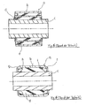
- FIG. 5 corresponds to a cross-sectional view of the elastic bearing generally designated by reference numeral (a).
- the elastic bearing (a) has an outer bushing (b), a stronger inner bushing (c), which is surrounded by the outer bushing (b), and an elastomeric damping body (d) lying between the outer bushing (b) and the inner bushing (c).
- An intermediate ring (e) is embedded in the elastomeric damping body (d).
- the elastic bearing (a) known type has been proven in use, but is subject to some structural disadvantages in that it has a relatively large radial dimension due to the intermediate arrangement of the intermediate ring (e). Furthermore, it is relatively heavy because of the use of the relatively large amount of metal, in particular for the intermediate ring. Finally, the known elastic bearing is expensive to manufacture.
- GB 2 115 080 A discloses a pivot bearing with a bolt, a bearing body and an intermediate metal sleeve.
- the bearing body consists of an inner sleeve, on which a rubber body is vulcanized, and an inner sleeve coaxial with the outer sleeve.
- the rubber body may have an excess and be pressed between the inner and outer sleeves.
- EP 1 505 311 A1 known.
- EP 1 589 251 A1 discloses a bearing for a motor vehicle.
- the flange generates a local bias of the damping body, in particular adjacent to the axial end edge of the damping body.
- the circumferential recess is at least partially so occupied by the elastomer, in particular rubber, of the damping body, that a radially extending from the recess column on elastomer, in particular rubber, forms a resilient connection between the inner and the outer fitting as part of the damping body.
- a radial thickness of the at least one damping body column is greater than a radial thickness of the rest of the damping body.
- At least the damping body column preferably the entire damping body, is free of a rigid, surrounding of elastomer or rubber intermediate fitting, whereby an elastic, direct, continuous and uninterrupted elastomeric material connection to the outer fitting is formed.
- the damping body column is a part of a, made of an elastomeric piece, in particular molded, damping body. In this way, the production costs can be kept low while maintaining the advantages of the invention.
- the recess extends from the region of the axial end of the outer or the inner fitting towards an axial center of the bearing, without crossing a radial center axis of the bearing. In this way, a recessed, limited incision is made on the outside of the inner fitting, wherein in the central region of the inner fitting whose original unimpaired outer dimension, in particular outer diameter, remains.
- the axial dimension of the recess is less than one third of the axial dimension of the inner or outer fitting, in particular the shorter of the two.
- the axial dimension of the recess may correspond to five times a radial thickness of the damping body column.
- the axial dimension of the recess is 1 mm to 30 mm, preferably 10 mm, wide.
- a recess in the region of both axial ends of the outer or inner fitting is provided in each case. Both recesses are separated by a recess-free inner fitting intermediate section of larger outer dimensions.
- the inner fitting intermediate portion located between two recesses is in particular ideally cylindrical. The inner fitting intermediate portion extends from the facing circumferential recessed edges of the recesses.
- the recess is a groove or a recess in the inner fitting with a radial depth of 0.05 mm to 10 mm, preferably 0.5 mm formed.
- the groove may have a flat, essentially only axially extending bottom, from which both sides round groove edges extend to the groove-free outer side of larger outer dimensions of the inner fitting.
- the damping body has in cross-section two mutually facing U-shapes short leg.
- the U-legs are significantly shorter than the U-leg connecting U-web.
- an axial bulge is introduced into the damping body in the region of at least one of its axial ends.
- the bulge is radially surrounded by the inner armature and the outer armature.
- the bulge extends partially into the damper body column. In this way it is avoided that under radial load elastomeric material or rubber material is deformed out of the axial dimensions of the inner fitting and outer fitting out and may be injured by the sharp edges of the axial ends of the outer or inner fitting.
- the bulge is provided with at least one radial rear section. In this way, the distribution of stress within the elastomeric body can be improved.
- the outer fitting is provided with a constriction in the region of an axial center of the bearing, so that the damping body has a radial thickness of smaller dimension in the region of the constriction than in the remaining region.
- the constriction is formed by a radially inwardly directed nose on an inner side of the outer fitting.
- the constriction may be formed by a radially inwardly directed mold recess affecting the entire outer fitting.
- the axial dimension of the constriction is less than one third of the axial extent of the outer fitting.
- the axial dimension of the constriction is 1 mm to 30 mm, preferably 10 mm, wide.
- the constriction has a radial dimension of 0.05 mm to 5 mm, preferably 1.0 mm.
- the inner fitting is formed in the radial direction stronger than the outer fitting.
- the inner and outer fittings may be formed in particular hollow cylindrical, wherein the valves and the hollow cylindrical damping body are arranged concentrically with each other.
- the axial extent of the outer fitting is less than or equal to the axial extent of the inner fitting.
- the damping body can be integrally uninterrupted, extending continuously from one region of the axial end to the other region of the axial end of the outer fitting.
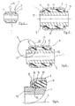
- FIG. 1 the elastic bearing of the first embodiment according to the invention is generally provided with the reference numeral 1.
- the reference numeral 1 For better readability of the further embodiments of the invention according to the FIGS. 2 to 4 the same or similar components are used.
- the elastic bearing 1 according to FIG. 1 has an outer sleeve 3, which is concentric with an inner sleeve 5 greater strength.
- the inner bush 5 is hollow cylindrical and is concentric with the longitudinal axis L.
- an outer sleeve 3 with the inner bushing 5 connecting elastomer damping body 8 is injected, which is without any intermediate fitting, such as an intermediate ring formed.
- the axial ends 7, 9 of the outer sleeve 3 are flanged radially inwardly to bias the injected Elastomerdämpfungsisson locally, at the axial height of the beading pressure.
- a recess 13 formed by a recess or a groove 13 is made on the outer side 11 of the inner bush 5.
- the recess 13 has a flat, axially extending bottom and rounded edge portions, which open to the outside of larger outer dimensions of the inner sleeve 5.
- the recess 13 is about 10 mm wide and about 1 mm deep into the inner sleeve 5 introduced.
- the recesses 13 are each bounded axially by radially encircling boundary edges.
- the facing boundary edges of the recesses 13 axially also define a substantially purely cylindrical intermediate portion 14.
- the intermediate portion 14 is formed without recess.
- the elastomeric damping body portion 16 located radially between the intermediate portion 14 and the outer fitting 3 comprises an ideal tubular cylindrical structure.
- the intermediate section 14 opposite portion of the outer fitting 3 comprises an equally purely cylindrical inside.
- FIG. 2 is the elastic bearing 1 instead of recesses adjacent to the radially inwardly bent ends 7, 9 provided with a radially inwardly formed mold recess 21 in the region of the central axis M, which forms a constriction of the outer sleeve 3 in the axial course.
- the elastomeric damping body 8 is formed at the axial height of the constriction with a smaller radial thickness than the remaining portion of the Elastomerdämpfungs stressess 8.
- the constriction gradually descending toward a depression of the mold cavity 21 and gradually increasing from the depression is about 10 mm wide and reduces the radial strength of the elastomeric damping body 8 by about 1 mm.
- FIGS. 3 and 4 a further embodiment of the elastic bearing 1 according to the invention is shown, in which the solution aspects of the embodiment according to the Figures 1 and 2 combined.
- the elastic bearing 1 according to FIG. 3 In addition to the recesses 13 also has a shape indentation 21, whereby an optimal distribution of the tension within the Elastomerdämpfungs stressess 8 is achieved.
- FIGS. 1 and 3 an elastic bearing is proposed, in which an optimized ratio of radial stiffness to torsional stiffness or gimbal stiffness is achieved.
- an axial recess or recess 31 is formed in the axial edge region 15 of the elastomer body 8, which are provided with radial undercuts 33, 35.
- the indentation 31 it is achieved that, when the axial edge region 15 is stretched, no elastomeric material is removed from the space between the outer sleeve 3 and the inner bushing can reach socket 5. In this way, a violation of the Elastomerdämpfungs stresses 8 due to sharp edges on the outer sleeve 3 is avoided.
- connection column 37 is a part of the one-piece elastomeric damping body 8.
Landscapes
- Engineering & Computer Science (AREA)
- General Engineering & Computer Science (AREA)
- Mechanical Engineering (AREA)
- Vibration Prevention Devices (AREA)
- Springs (AREA)
- Support Of The Bearing (AREA)
Claims (13)
- Support élastique avec une armature interne, une armature externe entourant radialement l'armature interne et un corps amortisseur en élastomère, en particulier en caoutchouc, s'étendant axialement entre les armatures interne et externe et les reliant l'une à l'autre, au moins une extrémité axiale de l'armature externe étant limitée radialement vers l'intérieur, de sorte que le corps amortisseur est localement allongé préalablement par pression au niveau de l'extrémité axiale limitée dès avant le montage final, caractérisé en ce que, pour compenser l'allongement par pression préalable du corps amortisseur environ à hauteur axiale de cette au moins une extrémité axiale (7, 9) de l'armature externe, on réalise une cavité circonférentielle (13) dans l'armature interne, laquelle cavité (13) est occupée au moins partiellement par l'élastomère, en particulier du caoutchouc, du corps amortisseur, de telle sorte qu'un noyau (37) en élastomère, en particulier en caoutchouc, s'étendant radialement depuis la cavité (13) en tant que partie du corps amortisseur forme un lien élastique entre l'armature interne et l'armature externe.
- Support élastique selon la revendication 1, caractérisé en ce qu'au moins le noyau du corps amortisseur (37), de préférence l'ensemble du corps amortisseur, est libre de toute armature intermédiaire périphérique rigide, en élastomère, en particulier en caoutchouc, et forme un lien élastique direct continu vers l'armature externe.
- Support élastique selon l'une des revendications précédentes, caractérisé en ce que le noyau du corps amortisseur (37) est une partie d'un corps amortisseur fabriqué en une seule pièce, en particulier moulé par injection.
- Support élastique selon l'une des revendications 1 à 3, caractérisé en ce que la dimension axiale de la cavité (13) correspond sensiblement à cinq fois une épaisseur radiale du noyau du corps amortisseur (37), de préférence avec une largeur de 1 mm à 30 mm.
- Support élastique selon l'une des revendications 1 à 4, caractérisé en ce que l'on prévoit respectivement une cavité (13) dans la zone des deux extrémités axiales de l'armature externe ou interne, les deux cavités (13) étant séparées par une section intermédiaire (14) sans cavité, en particulier cylindrique, laquelle s'étend depuis les bords de renforcement situés en vis-à-vis.
- Support élastique selon l'une des revendications 1 à 5, caractérisé en ce que la cavité (13) est une rainure réalisée avec une profondeur radiale de 0,05 mm à 10 mm, de préférence de 0,1 mm à 0,5 mm, la rainure présentant en particulier un fond de rainure plat s'étendant sensiblement seulement axialement, à partir duquel des bords de rainure ronds s'étendent des deux côtés vers le côté extérieur sans rainure de l'armature interne.
- Support élastique selon l'une des revendications 1 à 6, caractérisé en ce que le corps amortisseur présente, dans la zone d'au moins l'une de ses extrémités axiales, un évidement axial (31), lequel est entouré radialement par l'armature interne et l'armature externe et s'étend partiellement dans le noyau du corps d'amortissement (37), moyennant quoi en particulier l'évidement (31) présente au moins une contre-dépouille radiale (33, 35).
- Support élastique selon l'une des revendications 1 à 7, caractérisé en ce que dans la zone d'un milieu axial du support (1), l'armature externe est munie d'un rétrécissement, de sorte que le corps amortisseur présente dans la zone du rétrécissement une épaisseur radiale de dimension inférieure à celle de la zone résiduelle, le rétrécissement étant en particulier formé par un bec orienté radialement vers l'intérieur sur le côté intérieur de l'armature externe, moyennant quoi le rétrécissement est en particulier formé par une forme en retrait (21) orientée vers l'intérieur de l'armature externe.
- Support élastique selon la revendication 8, caractérisé en ce que la dimension axiale du rétrécissement présente une largeur de moins d'un tiers de l'armature externe, de préférence de 1 mm à 30 mm.
- Support élastique selon la revendication 8 ou 9, caractérisé en ce que le rétrécissement présente une dimension radiale de 0,05 mm à 5 mm, de préférence de 10 mm.
- Support élastique selon l'une des revendications 1 à 10, caractérisé en ce que l'armature interne en direction radiale est réalisée de manière plus épaisse que l'armature externe.
- Support élastique selon l'une des revendications 1 à 11, caractérisé en ce que les armatures interne et externe sont en particulier des gaines cylindriques creuses, les gaines et en particulier le corps d'amortissement cylindrique creux étant disposés de manière concentrique les uns par rapport aux autres.
- Support élastique selon l'une des revendications 1 à 12, caractérisé en ce que l'étendue axiale de l'armature externe est inférieure ou égale à l'étendue axiale de l'armature interne, moyennant quoi en particulier le corps amortisseur s'étend sans interruption, d'une seule traite depuis une zone de l'extrémité axiale jusqu'à l'autre zone de l'extrémité axiale de l'armature externe.
Applications Claiming Priority (1)
| Application Number | Priority Date | Filing Date | Title |
|---|---|---|---|
| DE200710037111 DE102007037111A1 (de) | 2007-08-07 | 2007-08-07 | Elastisches Lager |
Publications (3)
| Publication Number | Publication Date |
|---|---|
| EP2023005A2 EP2023005A2 (fr) | 2009-02-11 |
| EP2023005A3 EP2023005A3 (fr) | 2010-02-03 |
| EP2023005B1 true EP2023005B1 (fr) | 2013-01-23 |
Family
ID=39962972
Family Applications (1)
| Application Number | Title | Priority Date | Filing Date |
|---|---|---|---|
| EP20080012245 Active EP2023005B1 (fr) | 2007-08-07 | 2008-07-07 | Support élastique |
Country Status (2)
| Country | Link |
|---|---|
| EP (1) | EP2023005B1 (fr) |
| DE (1) | DE102007037111A1 (fr) |
Families Citing this family (2)
| Publication number | Priority date | Publication date | Assignee | Title |
|---|---|---|---|---|
| JP6054707B2 (ja) * | 2012-11-02 | 2016-12-27 | 山下ゴム株式会社 | 防振装置 |
| DE102018105008B4 (de) * | 2018-03-05 | 2022-09-15 | Benteler Automobiltechnik Gmbh | Lageranordnung für ein Fahrzeug |
Family Cites Families (7)
| Publication number | Priority date | Publication date | Assignee | Title |
|---|---|---|---|---|
| DE3205716C2 (de) * | 1982-02-18 | 1985-03-28 | Daimler-Benz Ag, 7000 Stuttgart | Elastisch nachgiebiges Schwenklager zur gegenseitigen schwenkbaren Verbindung eines tragenden und eines schwenkbaren Teiles eines Kraftfahrzeuges, beispielsweise eines Radträgers mit einem Radführungsglied |
| DE3419967C2 (de) * | 1984-05-29 | 1986-07-10 | Boge Gmbh, 5208 Eitorf | Elastisches Gelenk, Kupplung oder dergleichen |
| DE10227978B4 (de) * | 2002-06-22 | 2005-12-29 | Zf Boge Elastmetall Gmbh | Dämfungselement |
| EP1505311A1 (fr) * | 2003-08-06 | 2005-02-09 | ZF FRIEDRICHSHAFEN Aktiengesellschaft | Coussinet |
| DE102004019917A1 (de) * | 2004-04-21 | 2005-11-17 | Zf Friedrichshafen Ag | Lager für ein Kraftfahrzeug |
| DE102004045064A1 (de) * | 2004-09-15 | 2006-03-30 | Zf Friedrichshafen Ag | Elastomerlager |
| DE202005009951U1 (de) * | 2005-06-24 | 2005-09-29 | Dr.Ing.H.C. F. Porsche Ag | Lager, insbesondere für einen Stabilisator |
-
2007
- 2007-08-07 DE DE200710037111 patent/DE102007037111A1/de not_active Withdrawn
-
2008
- 2008-07-07 EP EP20080012245 patent/EP2023005B1/fr active Active
Also Published As
| Publication number | Publication date |
|---|---|
| EP2023005A2 (fr) | 2009-02-11 |
| EP2023005A3 (fr) | 2010-02-03 |
| DE102007037111A1 (de) | 2009-02-26 |
Similar Documents
| Publication | Publication Date | Title |
|---|---|---|
| DE102008008246B4 (de) | Buchsenlager mit verringertem Bauraumbedarf | |
| EP2449274B1 (fr) | Joint à rotule | |
| EP2090801B1 (fr) | Soufflet roulant d'un ressort pneumatique | |
| DE102012207527B4 (de) | Hülsengelenk für ein Fahrzeug | |
| DE112007000008T5 (de) | Vibrationsdämpfungsbuchse | |
| DE102007038493B4 (de) | Elastomeres Buchsenlager mit hydraulischer Dämpfung | |
| EP1736681B1 (fr) | Manchon avec butée radiale et/ou axiale et procédé pour la réalisation d'une butée axiale d'un manchon | |
| EP1611367B1 (fr) | Palier a douille en caoutchouc a amortissement hydraulique pour un montage vertical | |
| EP1995088A2 (fr) | Elément de palier d'insertion, élément de palier d'insertion élastique et dispositif de support de jambe de suspension à ressort | |
| EP1287273B1 (fr) | Palier a coussinet-douille a amortissement hydraulique | |
| DE102013204995A1 (de) | Verfahren zum Herstellen eines Lagers und Lager | |
| DE102006021011B4 (de) | Buchsenlager mit axialseitig profiliertem Lagerkörper | |
| DE10241246B4 (de) | Elastisches Gummilager | |
| EP1409887A1 (fr) | Silentbloc a element de renforcement | |
| EP1586789A1 (fr) | Support élastique pour une cabine de véhicule | |
| EP2023005B1 (fr) | Support élastique | |
| DE102018208298A1 (de) | Koppelstange, Radaufhängung und Verfahren zur Herstellung einer Koppelstange | |
| DE102004014328B4 (de) | Hydraulisch dämpfendes Gummilager | |
| DE10329069A1 (de) | Vibrationsisolierende Buchse | |
| EP1908987A2 (fr) | Coussinet élastique avec amortissement hydraulique | |
| DE19937714A1 (de) | Hülsengummifeder, sowie Verfahren zu deren Herstellung | |
| DE102006052918B4 (de) | Axial vorgespanntes Hydrolager | |
| DE102012201512A1 (de) | Querlenkerrohteil, Querlenker und Verfahren zur Montage eines Querlenkers | |
| EP4237700A1 (fr) | Ressort pneumatique | |
| DE102006052251B4 (de) | Hydrobuchse mit verbesserter Dauerlauffestigkeit |
Legal Events
| Date | Code | Title | Description |
|---|---|---|---|
| PUAI | Public reference made under article 153(3) epc to a published international application that has entered the european phase |
Free format text: ORIGINAL CODE: 0009012 |
|
| AK | Designated contracting states |
Kind code of ref document: A2 Designated state(s): AT BE BG CH CY CZ DE DK EE ES FI FR GB GR HR HU IE IS IT LI LT LU LV MC MT NL NO PL PT RO SE SI SK TR |
|
| AX | Request for extension of the european patent |
Extension state: AL BA MK RS |
|
| RAP1 | Party data changed (applicant data changed or rights of an application transferred) |
Owner name: ANVIS DEUTSCHLAND GMBH |
|
| PUAL | Search report despatched |
Free format text: ORIGINAL CODE: 0009013 |
|
| AK | Designated contracting states |
Kind code of ref document: A3 Designated state(s): AT BE BG CH CY CZ DE DK EE ES FI FR GB GR HR HU IE IS IT LI LT LU LV MC MT NL NO PL PT RO SE SI SK TR |
|
| AX | Request for extension of the european patent |
Extension state: AL BA MK RS |
|
| 17P | Request for examination filed |
Effective date: 20100415 |
|
| AKX | Designation fees paid |
Designated state(s): CZ DE ES FR PL SK |
|
| 17Q | First examination report despatched |
Effective date: 20111222 |
|
| GRAP | Despatch of communication of intention to grant a patent |
Free format text: ORIGINAL CODE: EPIDOSNIGR1 |
|
| GRAS | Grant fee paid |
Free format text: ORIGINAL CODE: EPIDOSNIGR3 |
|
| GRAA | (expected) grant |
Free format text: ORIGINAL CODE: 0009210 |
|
| AK | Designated contracting states |
Kind code of ref document: B1 Designated state(s): CZ DE ES FR PL SK |
|
| REG | Reference to a national code |
Ref country code: DE Ref legal event code: R096 Ref document number: 502008009152 Country of ref document: DE Effective date: 20130321 |
|
| PG25 | Lapsed in a contracting state [announced via postgrant information from national office to epo] |
Ref country code: ES Free format text: LAPSE BECAUSE OF FAILURE TO SUBMIT A TRANSLATION OF THE DESCRIPTION OR TO PAY THE FEE WITHIN THE PRESCRIBED TIME-LIMIT Effective date: 20130504 |
|
| PG25 | Lapsed in a contracting state [announced via postgrant information from national office to epo] |
Ref country code: PL Free format text: LAPSE BECAUSE OF FAILURE TO SUBMIT A TRANSLATION OF THE DESCRIPTION OR TO PAY THE FEE WITHIN THE PRESCRIBED TIME-LIMIT Effective date: 20130123 |
|
| PG25 | Lapsed in a contracting state [announced via postgrant information from national office to epo] |
Ref country code: SK Free format text: LAPSE BECAUSE OF FAILURE TO SUBMIT A TRANSLATION OF THE DESCRIPTION OR TO PAY THE FEE WITHIN THE PRESCRIBED TIME-LIMIT Effective date: 20130123 Ref country code: CZ Free format text: LAPSE BECAUSE OF FAILURE TO SUBMIT A TRANSLATION OF THE DESCRIPTION OR TO PAY THE FEE WITHIN THE PRESCRIBED TIME-LIMIT Effective date: 20130123 |
|
| PLBE | No opposition filed within time limit |
Free format text: ORIGINAL CODE: 0009261 |
|
| STAA | Information on the status of an ep patent application or granted ep patent |
Free format text: STATUS: NO OPPOSITION FILED WITHIN TIME LIMIT |
|
| 26N | No opposition filed |
Effective date: 20131024 |
|
| REG | Reference to a national code |
Ref country code: DE Ref legal event code: R097 Ref document number: 502008009152 Country of ref document: DE Effective date: 20131024 |
|
| REG | Reference to a national code |
Ref country code: FR Ref legal event code: PLFP Year of fee payment: 8 |
|
| PGFP | Annual fee paid to national office [announced via postgrant information from national office to epo] |
Ref country code: FR Payment date: 20150626 Year of fee payment: 8 |
|
| REG | Reference to a national code |
Ref country code: DE Ref legal event code: R084 Ref document number: 502008009152 Country of ref document: DE |
|
| PG25 | Lapsed in a contracting state [announced via postgrant information from national office to epo] |
Ref country code: FR Free format text: LAPSE BECAUSE OF NON-PAYMENT OF DUE FEES Effective date: 20160801 |
|
| REG | Reference to a national code |
Ref country code: FR Ref legal event code: ST Effective date: 20170331 |
|
| PGFP | Annual fee paid to national office [announced via postgrant information from national office to epo] |
Ref country code: DE Payment date: 20250722 Year of fee payment: 18 |