EP2023099A2 - Dispositif de détermination d'une force s'exerçant sur un moyen de traction - Google Patents
Dispositif de détermination d'une force s'exerçant sur un moyen de traction Download PDFInfo
- Publication number
- EP2023099A2 EP2023099A2 EP08013002A EP08013002A EP2023099A2 EP 2023099 A2 EP2023099 A2 EP 2023099A2 EP 08013002 A EP08013002 A EP 08013002A EP 08013002 A EP08013002 A EP 08013002A EP 2023099 A2 EP2023099 A2 EP 2023099A2
- Authority
- EP
- European Patent Office
- Prior art keywords
- sensor
- arrangement according
- rings
- traction means
- solid
- Prior art date
- Legal status (The legal status is an assumption and is not a legal conclusion. Google has not performed a legal analysis and makes no representation as to the accuracy of the status listed.)
- Withdrawn
Links
Images



Classifications
-
- G—PHYSICS
- G01—MEASURING; TESTING
- G01G—WEIGHING
- G01G19/00—Weighing apparatus or methods adapted for special purposes not provided for in the preceding groups
- G01G19/14—Weighing apparatus or methods adapted for special purposes not provided for in the preceding groups for weighing suspended loads
- G01G19/18—Weighing apparatus or methods adapted for special purposes not provided for in the preceding groups for weighing suspended loads having electrical weight-sensitive devices
-
- G—PHYSICS
- G01—MEASURING; TESTING
- G01G—WEIGHING
- G01G23/00—Auxiliary devices for weighing apparatus
- G01G23/18—Indicating devices, e.g. for remote indication; Recording devices; Scales, e.g. graduated
- G01G23/36—Indicating the weight by electrical means, e.g. using photoelectric cells
- G01G23/37—Indicating the weight by electrical means, e.g. using photoelectric cells involving digital counting
- G01G23/3728—Indicating the weight by electrical means, e.g. using photoelectric cells involving digital counting with wireless means
-
- G—PHYSICS
- G01—MEASURING; TESTING
- G01G—WEIGHING
- G01G3/00—Weighing apparatus characterised by the use of elastically-deformable members, e.g. spring balances
- G01G3/12—Weighing apparatus characterised by the use of elastically-deformable members, e.g. spring balances wherein the weighing element is in the form of a solid body stressed by pressure or tension during weighing
- G01G3/14—Weighing apparatus characterised by the use of elastically-deformable members, e.g. spring balances wherein the weighing element is in the form of a solid body stressed by pressure or tension during weighing measuring variations of electrical resistance
- G01G3/1402—Special supports with preselected places to mount the resistance strain gauges; Mounting of supports
- G01G3/141—Special supports with preselected places to mount the resistance strain gauges; Mounting of supports the supports being disc or ring shaped
-
- G—PHYSICS
- G01—MEASURING; TESTING
- G01L—MEASURING FORCE, STRESS, TORQUE, WORK, MECHANICAL POWER, MECHANICAL EFFICIENCY, OR FLUID PRESSURE
- G01L1/00—Measuring force or stress, in general
- G01L1/20—Measuring force or stress, in general by measuring variations in ohmic resistance of solid materials or of electrically-conductive fluids; by making use of electrokinetic cells, i.e. liquid-containing cells wherein an electrical potential is produced or varied upon the application of stress
- G01L1/22—Measuring force or stress, in general by measuring variations in ohmic resistance of solid materials or of electrically-conductive fluids; by making use of electrokinetic cells, i.e. liquid-containing cells wherein an electrical potential is produced or varied upon the application of stress using resistance strain gauges
- G01L1/2206—Special supports with preselected places to mount the resistance strain gauges; Mounting of supports
- G01L1/2231—Special supports with preselected places to mount the resistance strain gauges; Mounting of supports the supports being disc- or ring-shaped, adapted for measuring a force along a single direction
-
- G—PHYSICS
- G01—MEASURING; TESTING
- G01L—MEASURING FORCE, STRESS, TORQUE, WORK, MECHANICAL POWER, MECHANICAL EFFICIENCY, OR FLUID PRESSURE
- G01L5/00—Apparatus for, or methods of, measuring force, work, mechanical power, or torque, specially adapted for specific purposes
- G01L5/04—Apparatus for, or methods of, measuring force, work, mechanical power, or torque, specially adapted for specific purposes for measuring tension in flexible members, e.g. ropes, cables, wires, threads, belts or bands
- G01L5/10—Apparatus for, or methods of, measuring force, work, mechanical power, or torque, specially adapted for specific purposes for measuring tension in flexible members, e.g. ropes, cables, wires, threads, belts or bands using electrical means
- G01L5/103—Apparatus for, or methods of, measuring force, work, mechanical power, or torque, specially adapted for specific purposes for measuring tension in flexible members, e.g. ropes, cables, wires, threads, belts or bands using electrical means using sensors fixed at one end of the flexible member
Definitions
- the invention relates to an arrangement for determining a force acting on a traction means by means of a sensor.
- Traction means are generally resilient with only limited forces. Even if these forces can assume very high values depending on the configuration of the traction device, there is nevertheless a limit value which, if exceeded, results in impairment or even destruction of the traction device. Even before reaching this limit, a load can be reached at which machine components or the machine itself can be damaged or completely destroyed. For example, pulleys, rollers, axles, bearings or motors can be affected. In addition, there is the possibility that it comes to a tilting of the machine due to an excessive load. Therefore, it is often desirable or necessary to be able to know or at least estimate the force acting on the traction means. Exemplary applications of such arrangements include cranes, forklifts, elevators, cable cars or the like.
- the load of a traction device is determined in various ways.
- the electric power absorbed by the electric motor is determined.
- the absorbed electrical power depends on the torque acting on the motor shaft and thus on the load of the motor. The higher the torque, the higher the power consumption of the motor will be.
- a circuit can deactivate the motor and thereby avoid excessive loading of the motor, the traction means or other machine parts.
- the force acting on the traction means is also determined indirectly.
- the pressure prevailing in the pneumatic cylinder can be determined and from this the load of the traction device can be estimated.
- Forklifts have pneumatic cylinders in which a piston is movably arranged. During movement of the piston, a deflection roller is moved. About the pulley a pull chain is steered, which is connected at one end to the frame of the forklift and at the other End is attached to a mast. If the piston moves upwards, the pull chain is moved over the deflection roller and the mast is pulled upwards.
- the tension chain - the pressure in the pneumatic cylinder can be determined. This depends on the load of the mast.
- the present invention is therefore the object of an arrangement of the type mentioned in such a design and further that the force acting on the traction means can be measured as easily and with the simplest structural means.
- the above object is achieved by the features of claim 1.
- the arrangement in question is characterized in that the traction device extends through a solid body and that the sensor is supported on the solid and measures the force acting between the traction means and the solid force.
- a force acting on a traction device can be determined most simply where it is introduced into another solid. By measuring the force at the point of introduction of force, it is easiest to conclude the force acting on the traction device as a whole.
- the connection between traction means and the solid body is configured in such a way that the traction means extends through the solid body.
- This solid can in principle be formed by a wide variety of materials and have a wide variety of shapes. The only prerequisite is that the force acting on the traction means can be absorbed by the solid.
- This force is determined by a sensor, which is supported on the solid. In this case, the sensor is arranged such that it acts between the traction means and the solid Strength measures.
- the force introduced by the traction means into the solid can be determined and from this the force acting on the traction means can be deduced. In some cases, this may require the use of information about the geometry and / or dynamics of the assembly, which will generally be present.
- the solid can be realized by a variety of known from practice embodiments.
- the solid body could be formed, for example, as a beam, traverse, bow or carrier.
- Other embodiments are conceivable.
- the solid body can be provided only for deriving the force acting on the traction means, but could also fulfill additional tasks.
- the solid body in a frame construction take over the derivation or forwarding of other forces. In this case, it must merely be ensured that the additional force introduced via the traction means can be absorbed by the solid body. However, this is a generally easy to fulfill requirement.
- the solid body can in principle consist of a wide variety of materials or combinations of materials. Steel, wood or plastics can be used as well as reinforced concrete or fiber composites. The material used need only be mechanically stable enough. In addition, it is comparatively irrelevant in which profile the solid is formed.
- the carrier may have a simple rectangular cross-section, but could also consist of a relatively arbitrarily complicated constructed profile. This will generally be negligible.
- the traction means can also be realized in various ways.
- the traction means could be formed by a rope, a chain or a rod.
- the only prerequisite is that the traction means is suitable for forwarding the attacking forces.
- the traction means is rigid - such as in a rod - or only in one or more directions flexible - such as a chain or a rope - is configured, is essentially irrelevant.
- the traction means could consist of a wide variety of materials. Although in many cases the traction means will be made of a steel, it could also be made of plastic, carbon, plastic or other fibers and fiber composites.
- the traction means could be part of a machine.
- the traction means could comprise the load chain of the forklift truck.
- the carrying part of the elevator could act as a pulling means.
- the traction means could be part of the machine and take over functions of this machine.
- the solid body could be part of a machine.
- the solid could be formed by a cross member to which the elevator is attached.
- the solid could be formed by a bracket to a base or intermediate station. The way in which the solid is formed will generally depend on the particular application.
- traction means and solids could be part of the same machine.
- the traction means is formed by the load chain of the forklift, while a frame part of the forklift or a part of the mast forms the solid. Traction means and solids are thus part of the same machine. In other machines, corresponding embodiments are conceivable.
- the solid is not part of a machine.
- the traction cable of the crane could be attached to a support which is anchored to the ground.
- On the pull rope would attack the forces generated by an engine of the crane, which are discharged into the carrier.
- the carrier - the solid - would not be part of a machine in the strict sense.
- the arrangement according to the invention is used in connection with a forklift.
- the force acting on the load chain or other traction means is determined. This force is essentially dependent on which loads are lifted with the forklift. The heavier the lifted loads, the higher forces must be applied by the traction means.
- a sensor is at the attachment point of the traction means on the frame of the forklift arranged. Alternatively or additionally, the sensor may be arranged on an element of the mast. This can be used to determine when the forklift is operating outside the allowable load range.
- a fastening means could be attached to the traction means.
- the movement of the traction means would be prevented at least in one direction and - with a suitable attachment - a force introduction into the solid can be made possible.
- the fastener could be realized by a variety of known from practice arrangements. By way of example only, reference may be made to the use of a clamp, a bolt, a snap ring or the like as a fastener.
- a coupling element could be attached to the end of the traction means a coupling element to which the fastening means is attached.
- the coupling element could have suitable grooves, holes, threads or other means to allow attachment of a fastener.
- the fastening means could be formed by a nut, which may be secured by a lock nut.
- the force acting on the traction means would be introduced via the attachment means, which can then be considered as part of the traction means, and via the sensor in the solid state.
- the senor comprises a base body.
- This body is made of a solid but deformable material within certain limits.
- steels come into question. However, other materials can be used which are capable of absorbing the forces occurring.
- the main body preferably has two nested rings.
- an outer ring could be provided within which an inner ring is arranged.
- These rings are preferably formed rigid.
- the rings could in principle have a variety of geometric configurations.
- the rings could be executed by polygons, ellipses or relatively arbitrarily structured structures.
- the rings are circular and are designed plan on their faces.
- the rings could be arranged concentrically.
- the two rings of the sensor are connected to each other by an annular bottom region or by webs.
- the bottom region or the webs are designed such that a deformability of the bottom region or the webs can be achieved.
- the extent of deformability depends on the size of the force to be measured. If only small maximum forces can be absorbed by the traction means, the bottom region or the webs could be comparatively thin and thus easily deformable. If the forces are relatively large, then the deformability could be relatively low. In this case, the webs or the bottom region may be formed correspondingly thick.
- strain gauges could be provided. These can be glued to the floor area or the webs or otherwise attached there. If a force acts on the rings, which leads to a deformation of the bottom area or the webs, the deformation can be detected by the strain gauges. This represents a measure of the load on the sensor and thus a measure of the force acting on the traction means. Together with the mechanical properties of the body, in particular its spring constant, the strain gauge can be concluded from the measurement signal to the applied force.
- the force acts on the sensor such that the two rings are loaded in the axial direction. This creates a shift of the rings in the axial direction.
- a relatively uniform deformation of the bottom region or the webs can be achieved.
- the rings could not be flush with each other at least in one direction.
- the outer ring could rest on the solid, while the inner ring terminates at a distance from the solid.
- the two rings could not end flush on the side facing away from the solid body.
- a disc is arranged on the side facing away from the solid side of the sensor, which mechanically faces the sensor protects against external influences.
- the disk could be arranged between the sensor and fastening means. In this case, with a non-flush finish of the rings on the side facing the disk, the inner ring could be in contact with the disk while the outer ring forms a gap with the disk.
- an evaluation circuit For evaluation of the measurement signals of the sensor, an evaluation circuit is provided. This could be designed in a variety of known from the practice types. Analogue evaluation circuits can be used as well as digital ones. In a preferred embodiment, a combination of analog and digital evaluation circuit is used.
- the evaluation circuit could be integrated in the interior of the sensor.
- the outer ring, the inner ring and the bottom region or the webs could be designed and arranged such that a concave region is formed between the rings.
- the evaluation could be arranged, which is preferably applied to an annular circuit board. This would make it possible to achieve an optimally short cable path between the sensor elements - the strain gauges - and the evaluation circuit.
- an electromagnetic shielding of the evaluation circuit is effectively achieved by the design of the metal sensor.
- the evaluation could be embedded in a potting compound. This would also provide protection against contamination of the electronics and moisture.
- the potting compound could be formed by a variety of materials known from practice and provided with the corresponding mechanical properties.
- the evaluation circuit could comprise a Wheatstone bridge.
- the sensor elements themselves could be connected to a Wheatstone bridge.
- Corresponding circuits are well known from practice.
- a digital evaluation signal is generated by the evaluation circuit.
- the output signal could be transmitted particularly insensitive to interference from the evaluation circuit or the sensor to the outside.
- the evaluation circuit preferably already comprises a digital processing element, which may be formed by a microcontroller.
- the processing element could also be formed by a digital signal processor or by specially designed circuitry in, for example, an Application Specific Integrated Circuit (ASIC) or a Field Gate Programmable Array (FGPA).
- ASIC Application Specific Integrated Circuit
- FGPA Field Gate Programmable Array
- the output signal could be pulse width modulated.
- the measured value of the sensor in the duty cycle, d. H. the ratio between the time in which the signal assumes a high level, and the period of the pulse width-modulated signal, are encoded.
- This embodiment would be advantageous in that at a receiver, the pulse width modulated signal can be decoded by means of a simple counter. An analog / digital converter is not needed.
- the output signal from the sensor could be provided a measuring cable.
- the output signal could be output via a wireless connection.
- the power supply could also be realized by a battery or an accumulator.
- the measured values could be fed to a control unit, with which the function of the machine is controlled. In this way, for example, could be stopped at too high a load of the traction means of the engine of the machine. If the arrangement is used, for example, in a forklift truck, tilting of the forklift could be prevented in this way.
- the memory preferably consists of a non-volatile memory that can hold stored data without power supply.
- suitable memories are known in practice and readily available.
- the memory could be integrated on the one hand in an external device, for example in a control unit of the machine. On the other hand, the memory could be part of the evaluation circuit. This would allow logging to be used independently of the control system used. For reading out the memory, corresponding wired or wireless interfaces could be provided.
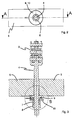
- Fig. 1 shows an embodiment of an inventive arrangement 1 for measuring a force acting on a traction means 2 force.
- the traction means 2 is formed by a chain 3, at the end of a coupling element 4 is formed.
- the coupling element 4 is passed through a passage hole of a solid 5 in the form of a traverse.
- the traction means 2 is thus formed by the chain 3 and the coupling element 4 and extends through the solid 5 therethrough.
- the traction means 2 is fixed by a fastening means 6 in the pulling direction.
- the fastening means 6 is formed by a nut 7, which is secured by a lock nut 8. By adjusting the nut and the lock nut length adjustment of the chain can be achieved.
- a sensor 9 and a disc 10 are arranged.
- Fig. 2 is the arrangement 1 according to Fig. 1 with a view from below shown again.
- the solid 5 through which the coupling element 4 extends.
- the coupling element 4 is secured by the fastening means 6.
- the sensor 9 and the disc 10 is arranged, which in Fig. 2 overlap.
- Fig. 1 The arrangement according to Fig. 1 is in Fig. 3 shown in section. The cut runs along the in Fig. 2 Here, it can be clearly seen that the coupling element 4 is passed through a through hole through the solid 5 and is secured on the opposite side by the nut 7 and the lock nut 8. Between the nut 7 and the solid 5, the sensor 9 and the disc 10 are arranged.
- the sensor is again as a detail magnification in Fig. 4 shown.
- the sensor 9 is embedded in a slight depression in the solid 5 and consists of a base body 11 in which an outer ring 12 and an inner ring 13 is formed.
- the two rings 12, 13 are connected to each other via an annular bottom portion 14.
- the outer ring 12 is in direct contact with the solid 5, while the inner ring 13 terminates at a distance from the solid 5.
- a gap 15 is formed between the inner ring 13 and the solid 5.
- the inner ring 13 is in contact with the disc 10, while a gap between the outer ring 12 and the disc 10 is formed.
- the inner ring 13 When the sensor is loaded by a force directed upward in the FIGURE, the inner ring 13 is displaced relative to the outer ring 12. The gap 15 is reduced as a function of the load. When the maximum load is reached, the inner ring 13 strikes on the solid body 5 and the outer ring 12 on the disc 10, so that an overload of the sensor is excluded. As a result, the sensor is effectively protected against destruction by excessive loads.
- the bottom portion 14 is deformed. This deformation is detected by strain gauges 16 which are glued to the bottom region 14.
- the measurement signals of the strain gauges 16 are an evaluation circuit, which is arranged on an annular plate 17, fed and evaluated there.
- the board 17 is arranged in a formed by the outer ring 12, the bottom portion 14 and the inner ring 13 concave portion and embedded in a potting compound 18 for protection against shock, dirt and moisture.
- the processed by the evaluation circuit measurement signals are given to the outside via a connecting cable 19, of which only a small portion is indicated in the figures.
- Fig. 5 shows the sensor 9 again in an oblique view, wherein the sensor compared to the illustration in Fig. 4 is shown rotated by 180 °, ie the view in Fig. 5 corresponds to a viewpoint from below in Fig. 4 ,
- the main body 11 in which an outer ring 12 and an inner ring 13 are formed.
- Between the rings 12, 13 of the concave portion is poured with a potting compound 18, in which the board 17 is embedded for the transmitter.
- Fig. 6 shows the same sensor 9 again in a plan.
- the board 17 is shown with recesses to release the view of the strain gauges 16.
- the strain gauges 16, which measure the deformation of the annular bottom portion 14 between the outer ring 12 and the inner ring 13, are connected to the board and thus to the evaluation circuit.
- the evaluation circuit determines the degree of deformation of the bottom area and outputs the information about the measuring cable 19 to the outside.
- the information may be pure data for loading the sensor. However, already upgraded data, for example in the form of assigned values, may also include the load of the traction device.
- FIG. 7 again a section through the sensor according to Fig. 5 and Fig. 6 along the section line CC. Again, the individual elements are a little clearer to recognize. To avoid repetition, please refer to the explanatory notes Fig. 4 directed.
Landscapes
- Physics & Mathematics (AREA)
- General Physics & Mathematics (AREA)
- Chemical & Material Sciences (AREA)
- Analytical Chemistry (AREA)
- Engineering & Computer Science (AREA)
- Computer Networks & Wireless Communication (AREA)
- Force Measurement Appropriate To Specific Purposes (AREA)
Applications Claiming Priority (1)
| Application Number | Priority Date | Filing Date | Title |
|---|---|---|---|
| DE200710035947 DE102007035947A1 (de) | 2007-07-30 | 2007-07-30 | Anordnung zur Ermittlung einer an einem Zugmittel angreifenden Kraft |
Publications (2)
| Publication Number | Publication Date |
|---|---|
| EP2023099A2 true EP2023099A2 (fr) | 2009-02-11 |
| EP2023099A3 EP2023099A3 (fr) | 2011-08-31 |
Family
ID=39830247
Family Applications (1)
| Application Number | Title | Priority Date | Filing Date |
|---|---|---|---|
| EP08013002A Withdrawn EP2023099A3 (fr) | 2007-07-30 | 2008-07-18 | Dispositif de détermination d'une force s'exerçant sur un moyen de traction |
Country Status (2)
| Country | Link |
|---|---|
| EP (1) | EP2023099A3 (fr) |
| DE (1) | DE102007035947A1 (fr) |
Cited By (4)
| Publication number | Priority date | Publication date | Assignee | Title |
|---|---|---|---|---|
| WO2010102756A3 (fr) * | 2009-03-10 | 2011-09-09 | Hottinger Baldwin Messtechnik Gmbh | Dispositif pour remplir des récipients en fonction du poids |
| CN115585929A (zh) * | 2022-11-15 | 2023-01-10 | 安徽合力股份有限公司 | 一种叉车用可柔性调节的牵引工装 |
| US11579010B1 (en) * | 2019-03-21 | 2023-02-14 | Motion Laboratories, Inc. | Chain hoist with integral load cell |
| CN119754712A (zh) * | 2024-12-20 | 2025-04-04 | 中煤科工(天津)岩层智控科技有限公司 | 钻箱滑移输送装置 |
Families Citing this family (2)
| Publication number | Priority date | Publication date | Assignee | Title |
|---|---|---|---|---|
| DE102010047362A1 (de) * | 2010-10-05 | 2012-04-05 | Christa Reiners | Verfahren und Vorrichtung zum Prüfen der Stabilität eines Seil-Systems |
| DE102023128543A1 (de) * | 2023-10-18 | 2025-04-24 | HELLA GmbH & Co. KGaA | Verfahren zum Aufbauen einer Kraftsensorgruppe sowie Kraftsensorgruppe für ein Kraftfahrzeug |
Family Cites Families (8)
| Publication number | Priority date | Publication date | Assignee | Title |
|---|---|---|---|---|
| GB882989A (en) * | 1959-02-20 | 1961-11-22 | Schenck Gmbh Carl | Device for measuring forces |
| DE2730435A1 (de) * | 1977-07-06 | 1979-01-18 | Pfreundt Hans Guenther | Verfahren zur bestimmung der von einem gabelstapler gehobenen last und vorrichtung zur durchfuehrung dieses verfahrens |
| DE8530361U1 (de) * | 1985-10-26 | 1987-02-26 | Eisen- Und Drahtwerk Erlau Ag, 7080 Aalen | Kontrolleinrichtung zur Überlastkontrolle von Ketten |
| SE459616B (sv) * | 1987-10-01 | 1989-07-17 | Gunnebo Chain & Lifting Ab | Anordning foer tillfaellig maetning och kontroll av dragbelastningar var som helst utefter en kaetting |
| US5905211A (en) * | 1997-12-15 | 1999-05-18 | The United States Of America As Represented By The Secretary Of The Navy | Load monitor sheave |
| US6232566B1 (en) * | 1999-07-12 | 2001-05-15 | Gagetek Technologies, Holdings Company | Apparatus in a lifting device for reducing error in weight measurements |
| DE60210747T2 (de) * | 2001-02-23 | 2007-04-12 | Renold Plc | Belastungs-überwachungssystem für fördergutträger |
| DE202006015829U1 (de) * | 2006-10-16 | 2007-02-08 | Wika Alexander Wiegand Gmbh & Co. Kg | Zugkraftmessgerät |
-
2007
- 2007-07-30 DE DE200710035947 patent/DE102007035947A1/de not_active Withdrawn
-
2008
- 2008-07-18 EP EP08013002A patent/EP2023099A3/fr not_active Withdrawn
Cited By (4)
| Publication number | Priority date | Publication date | Assignee | Title |
|---|---|---|---|---|
| WO2010102756A3 (fr) * | 2009-03-10 | 2011-09-09 | Hottinger Baldwin Messtechnik Gmbh | Dispositif pour remplir des récipients en fonction du poids |
| US11579010B1 (en) * | 2019-03-21 | 2023-02-14 | Motion Laboratories, Inc. | Chain hoist with integral load cell |
| CN115585929A (zh) * | 2022-11-15 | 2023-01-10 | 安徽合力股份有限公司 | 一种叉车用可柔性调节的牵引工装 |
| CN119754712A (zh) * | 2024-12-20 | 2025-04-04 | 中煤科工(天津)岩层智控科技有限公司 | 钻箱滑移输送装置 |
Also Published As
| Publication number | Publication date |
|---|---|
| DE102007035947A1 (de) | 2009-02-12 |
| EP2023099A3 (fr) | 2011-08-31 |
Similar Documents
| Publication | Publication Date | Title |
|---|---|---|
| EP3632714B1 (fr) | Attelage doté d'un capteur | |
| EP4051613B1 (fr) | Dispositif de freinage pour une cabine d'ascenseur pourvu de dispositif de mesure de charge intégré et son utilisation dans une installation d'ascenseur et procédé | |
| DE102005030971B4 (de) | Kugelgelenk mit Sensoreinrichtung, Verfahren zur Belastungsmessung und Verfahren zur Verschleißmessung | |
| DE102007035947A1 (de) | Anordnung zur Ermittlung einer an einem Zugmittel angreifenden Kraft | |
| EP3359481B1 (fr) | Dispositif de support pour supporter un dispositif mobile | |
| EP1719992B1 (fr) | Palier à roulement linéaire avec jauge extensométrique appliquée au chariot de guidage | |
| EP1627212B1 (fr) | Capteur dynamometrique | |
| DE102004021840A1 (de) | Lade- und/oder Hubgerät, insbesondere Reachstacker | |
| DE102008058758A1 (de) | Kraftaufnehmer für mit einem Hydraulikzylinder betätigten Stützausleger | |
| DE102015004937A1 (de) | Kraftmesssystem mit Doppelsensor | |
| DE102018214811A1 (de) | Handwerkzeug mit Messeinrichtung | |
| WO2012031961A1 (fr) | Dispositif de mesure de charge pour une installation d'ascenseur | |
| DE102011115910B4 (de) | Hebezeug, insbesondere Seil- oder Kettenzug | |
| DE102018107320B4 (de) | Kraftmesseinrichtung | |
| DE202018104957U1 (de) | Hakenmaulsicherungseinrichtung zur Sicherung eines Kranhakens | |
| EP1371604A2 (fr) | Dispositif de levage pour un chariot de manutention | |
| EP2116503B1 (fr) | Dispositif de levage | |
| DE20210958U1 (de) | Lasterfassungseinrichtung | |
| DE102017126182A1 (de) | Kraftmessvorrichtung mit Dynamikkompensation | |
| DE102012010248A1 (de) | Lastumschlag-Fahrzeug und Verfahren zur Bestimmung einer Gewichtsverteilung einer Last an einem Lastumschlag-Fahrzeug | |
| DE202006015829U1 (de) | Zugkraftmessgerät | |
| DE102019125291B4 (de) | Kraftsensorvorrichtung mit Gewindeeinsatz | |
| DE102020130437A1 (de) | Wägezelle | |
| DE102007034160A1 (de) | Kraftmessbolzen | |
| DE60320241T2 (de) | Kran mit einer Seilwinde und mit einer Zugsteuereinrichtung |
Legal Events
| Date | Code | Title | Description |
|---|---|---|---|
| PUAI | Public reference made under article 153(3) epc to a published international application that has entered the european phase |
Free format text: ORIGINAL CODE: 0009012 |
|
| AK | Designated contracting states |
Kind code of ref document: A2 Designated state(s): AT BE BG CH CY CZ DE DK EE ES FI FR GB GR HR HU IE IS IT LI LT LU LV MC MT NL NO PL PT RO SE SI SK TR |
|
| AX | Request for extension of the european patent |
Extension state: AL BA MK RS |
|
| PUAL | Search report despatched |
Free format text: ORIGINAL CODE: 0009013 |
|
| AK | Designated contracting states |
Kind code of ref document: A3 Designated state(s): AT BE BG CH CY CZ DE DK EE ES FI FR GB GR HR HU IE IS IT LI LT LU LV MC MT NL NO PL PT RO SE SI SK TR |
|
| AX | Request for extension of the european patent |
Extension state: AL BA MK RS |
|
| RIC1 | Information provided on ipc code assigned before grant |
Ipc: G01G 19/08 20060101ALI20110725BHEP Ipc: G01G 3/14 20060101AFI20110725BHEP |
|
| AKY | No designation fees paid | ||
| STAA | Information on the status of an ep patent application or granted ep patent |
Free format text: STATUS: THE APPLICATION IS DEEMED TO BE WITHDRAWN |
|
| REG | Reference to a national code |
Ref country code: DE Ref legal event code: R108 Effective date: 20120509 |
|
| 18D | Application deemed to be withdrawn |
Effective date: 20120201 |