EP2023113A2 - Capteur de pression à membrane - Google Patents
Capteur de pression à membrane Download PDFInfo
- Publication number
- EP2023113A2 EP2023113A2 EP08012187A EP08012187A EP2023113A2 EP 2023113 A2 EP2023113 A2 EP 2023113A2 EP 08012187 A EP08012187 A EP 08012187A EP 08012187 A EP08012187 A EP 08012187A EP 2023113 A2 EP2023113 A2 EP 2023113A2
- Authority
- EP
- European Patent Office
- Prior art keywords
- membrane
- carrier
- space
- pressure sensor
- sensor according
- Prior art date
- Legal status (The legal status is an assumption and is not a legal conclusion. Google has not performed a legal analysis and makes no representation as to the accuracy of the status listed.)
- Granted
Links
Images
Classifications
-
- G—PHYSICS
- G01—MEASURING; TESTING
- G01L—MEASURING FORCE, STRESS, TORQUE, WORK, MECHANICAL POWER, MECHANICAL EFFICIENCY, OR FLUID PRESSURE
- G01L23/00—Devices or apparatus for measuring or indicating or recording rapid changes, such as oscillations, in the pressure of steam, gas, or liquid; Indicators for determining work or energy of steam, internal-combustion, or other fluid-pressure engines from the condition of the working fluid
- G01L23/08—Devices or apparatus for measuring or indicating or recording rapid changes, such as oscillations, in the pressure of steam, gas, or liquid; Indicators for determining work or energy of steam, internal-combustion, or other fluid-pressure engines from the condition of the working fluid operated electrically
- G01L23/18—Devices or apparatus for measuring or indicating or recording rapid changes, such as oscillations, in the pressure of steam, gas, or liquid; Indicators for determining work or energy of steam, internal-combustion, or other fluid-pressure engines from the condition of the working fluid operated electrically by resistance strain gauges
-
- G—PHYSICS
- G01—MEASURING; TESTING
- G01L—MEASURING FORCE, STRESS, TORQUE, WORK, MECHANICAL POWER, MECHANICAL EFFICIENCY, OR FLUID PRESSURE
- G01L19/00—Details of, or accessories for, apparatus for measuring steady or quasi-steady pressure of a fluent medium insofar as such details or accessories are not special to particular types of pressure gauges
- G01L19/06—Means for preventing overload or deleterious influence of the measured medium on the measuring device or vice versa
- G01L19/0609—Pressure pulsation damping arrangements
-
- G—PHYSICS
- G01—MEASURING; TESTING
- G01L—MEASURING FORCE, STRESS, TORQUE, WORK, MECHANICAL POWER, MECHANICAL EFFICIENCY, OR FLUID PRESSURE
- G01L19/00—Details of, or accessories for, apparatus for measuring steady or quasi-steady pressure of a fluent medium insofar as such details or accessories are not special to particular types of pressure gauges
- G01L19/06—Means for preventing overload or deleterious influence of the measured medium on the measuring device or vice versa
- G01L19/0681—Protection against excessive heat
Definitions
- the invention relates to a pressure sensor, comprising a sensor carrier, on which a membrane carrier receiving a membrane is arranged and the sensor carrier has a connection channel to connect the membrane space arranged in front of the membrane with the pressure measuring chamber.
- the pressure sensors according to the invention are z. B. used for pressure measurement in internal combustion engines.
- the working space of the internal combustion engine would be the pressure measuring chamber in this case.
- the invention is in no way limited to this particular application.
- the pressure wave generated in the combustion process is accompanied by a temperature wave due to the explosive combustion process.
- this temperature shock wave with the pressure wave hits the sensor, d. H. in particular the membrane of the sensor.
- the membrane has a corresponding measuring device to measure its pressure-induced deformation and to determine therefrom the corresponding applied pressure.
- the membrane not only experiences a mechanical load due to the pressure wave, but it is also mechanically stressed due to the thermal shock wave. Due to the temperature-dependent linear expansion, the membrane is also mechanically deformed solely on account of the temperature level and leads to a measurement error, since the effect is not pressure-dependent.
- the senor is in the vicinity of the pressure measuring chamber, z. B. in the engine block, installed, which is well cooled by cooling water. Therefore, the sensor is generally thermally well connected to the engine block and therefore also well cooled.
- the deflection causes the incoming gas pressure wave, the membrane does not flow directly, but is guided at the deflection as a separate component and there of course also cooled. Furthermore, the deflection causes the gas pressure wave does not flow directly to the membrane, but first z. B. sweeps along the membrane support and also experiences a corresponding cooling there.
- the arrangement is cleverly chosen so that the high pressure in the connecting channel gas pressure wave first reaches the membrane support and only then the membrane and thus a more even as possible Heating of the membrane carrier and the membrane due to the inevitable temperature shock, which is associated with the gas pressure wave takes place.
- the deflection thus leads itself due to their representational execution to a cooling of the membrane space current gas pressure wave or the deflection ensures that the gas pressure wave first to other areas, eg. B. the membrane carrier is directed and also gives off temperature or the membrane support is heated so that sets a low temperature gradient at this.
- the membrane in the direction of the connecting channel, the membrane is covered by the deflection.
- the deflection learns the membrane also provides mechanical protection against z. B. entering the connecting channel particles.
- the invention provides that the deflection is located at the end of the connecting channel facing away from the pressure measuring chamber.
- the deflection is located at the end of the connecting channel facing away from the pressure measuring chamber.
- Such an embodiment has the advantage that with increasing distance from the pressure measuring chamber, the ambient temperature decreases accordingly, which is basically favorable for the measuring process.
- the pressure measuring chamber facing the end of the connecting channel is in the immediate vicinity of the hot explosive gases and an arrangement of the deflection in this area is not so efficient in his Cooling effect, since the environment at the beginning of this channel is much hotter than at the end facing away from the pressure measuring chamber end of the connecting channel.
- both a fundamentally cooler, formed as an object deflection is achieved, as well as achieved by the deflection current deflection of the gas pressure wave reaches generally colder areas of the membrane carrier or sensor carrier.
- the deflection is part of the sensor carrier.
- the sensor carrier is z. B. formed as a built-in part and has a corresponding external thread to screw it into a corresponding thread of the engine block.
- the sensor carrier itself carries the membrane carrier, which carries the membrane.
- the deflection is z. B. as an integral part of the sensor carrier or the sensor carrier consists of several elements, wherein the deflection is an element of the sensor carrier.
- the deflection is part of the membrane carrier.
- the deflection is designed as an element partially closing the connection channel with at least one opening arranged laterally, in particular at an angle to the connection channel.
- the element z. B. is formed as a disk or profile section and the connecting channel, which z. B. is arranged as a bore in the sensor carrier, is placed at the end remote from the pressure measuring chamber.
- a connecting space is provided, which in particular opens up the possibility that the gas pressure wave running to the membrane space cools down.
- the connection space is optimized for optimum temperature transition formed, so z. B. paid attention to large heat exchange surfaces and relatively high flow velocities of the gas pressure wave. It follows z. B. a relatively elongated sleeve-like formed with a small width design of the connecting space.
- connection space is bounded on the one hand by the membrane carrier and on the other hand by parts of the sensor carrier, in particular by the element.
- the sensor carrier is well thermally coupled with the cooling of the entire internal combustion engine.
- the membrane carrier is heated homogeneously by the incoming gas pressure wave and leads to a relatively smaller temperature coefficient at the membrane, also because the temperature level, which consists of the heat transfer, lowered becomes.
- the width of the connecting space is less than the diameter or the width of the connecting channel.
- connection space ie preferably the element or the sensor carrier or the membrane carrier.
- the membrane carrier in particular the region of the membrane carrier facing away from the membrane, serves for cooling the gas pressure wave.
- the gas pressure wave is skillfully deprived of temperature and it encounters a cooled gas pressure wave on the membrane to measure the pressure.
- the membrane carrier, and therefore also the regions of the membrane carrier actually carrying the membrane are heated in order to correspondingly reduce the temperature gradient in the membrane.
- the element or the deflection is preferably thermally well coupled to the sensor carrier, and the element or the deflection for cooling the gas pressure wave is provided and serves for this purpose.
- the length of the connection region between the membrane carrier and the sensor carrier is greater than the width of the connection space.
- the membrane space is bounded on at least one side by the membrane and the height of the membrane space is greater than the distance in the connecting space between the membrane carrier and sensor carrier.
- the height of the membrane space is defined by the distance of the membrane to the element or another element of the sensor carrier or membrane carrier.
- the membrane space is cylindrical or disc-like.
- the invention is not determined in any way. Due to the dimension chosen here, the incoming gas pressure wave slows down. As a result, the heat transfer is deteriorated because it depends on the flow rate. Of course, especially in the region of the membrane, impressing additional heat with a higher temperature into the membrane is not desired, which is why this represents a favorable arrangement.
- the membrane preferably has on the side facing away from the membrane space a measuring device for the pressure-induced membrane deformation.
- This is z. B. formed as strain gauges and realized according to the Wheatstone bridge circuit.
- the pressure-induced membrane deformation changes the electrical resistance in the strain gauge, which can be measured and evaluated by the measuring arrangement.
- a cup-like design of the membrane carrier wherein the membrane is formed by the bottom of the pot.
- Such a configuration is mechanically simple to produce and is preferably z. B. realized in metal, steel, iron or other alloys. It is advantageous that the arrangement is integrally formed, so the membrane z. B. is machined out of the pot by machining or used by appropriate welding or other methods of connection as the bottom of the pot in the annular surface of the membrane carrier and is connected.
- the lateral surfaces also form the connection region for connecting the membrane carrier to the sensor carrier. Conveniently, therefore, this lateral surface also serves to cool the gas pressure wave by being preferably flowed through by the deflection.
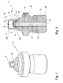
- FIG. 1 an exemplary pressure sensor 1 is shown in different variants. It should be noted that Fig. 2 not a true to scale sectional view of in Fig. 1 in a three-dimensional view shown pressure sensor 1 is. In Fig. 1 It should also be noted that this is the deflection 9 forming element 8 with the openings 12 is visible, which in the illustration after Fig. 2 is covered by the membrane carrier 3. It should be noted that the pressure sensor 1 has yet another the diaphragm support 3 overlapping housing, which is not shown here for illustrative and clarity reasons.
- the pressure sensor 1 is essentially composed of two elements, the sensor carrier 2 and the membrane carrier 3.
- the sensor carrier 2 is inserted with its lower end 20 in an opening of the pressure measuring chamber, z. B. screwed until z. B. the flange 21 abuts against the boundary wall of the pressure measuring chamber.
- the lower region 20 is therefore facing the pressure measuring chamber, run in the pressure measuring chamber z. B. in internal combustion engines with rapid sequence combustion processes, which lead to corresponding gas pressure waves and thermal shock waves.
- the sensor carrier 2 has a coaxially arranged in this embodiment, serving as a connecting channel 11 bore.
- the bore penetrates the sensor carrier 2 almost completely and is closed off at the end 22 remote from the lower, also hot end of the pressure sensor 1 by an element 8.
- the path of the pressure wave is indicated by arrows and denoted by the reference numerals 14, 14 'and 14' ', wherein the sequence of the wave is characterized by the increasing number of lines of the reference numeral 14.
- the pressure wave enters from the pressure measuring chamber in the connecting channel 11 and then propagates upwards.
- a deflection 9 is provided according to the invention.
- a pot-like Membrane carrier 3 is provided, the bottom of which forms the membrane 4.
- the membrane carrier 3 with the membrane 4 covers the element 8 between the element 8 and the membrane 4 results in the membrane space 7.
- the membrane chamber 7 is in communication with the connecting channel 11 via the connecting space 10. Since on the upper end 22 of the sensor carrier 2, the element 8 is arranged and actually conceals the inner, the pressure measuring chamber facing away from the end of the connecting channel 11, the element 8 has a plurality of openings 12 which establish a connection between the connecting space 10 and the Verbindunskanal 11.
- rotationally symmetrical flow openings 12 are provided equidistantly on the circumference of the disc-like element 8. It should be noted that the surface normal of the openings 12 are at an angle, in particular at right angles to the longitudinal axis 15 of the connecting channel 11.
- the openings 12 with respect to the connecting channel 11 the element 8 forms a deflection 9 for the upwardly running in the connecting channel 11 pressure wave 14, which is characterized in particular in the region of the element 8 by the deflected arrows 14 ''.
- the sensor carrier 2 is, as already stated, used in the cooled engine block or boundary wall of the pressure measuring chamber and kept at a relatively low temperature level.
- the gas pressure wave 14 now sweeps along the lateral surface 16 of the membrane carrier 3 and meets only after a certain cooling on the membrane 4.
- the already lowered temperature level in this area and the already warmed lateral surface 16 of the membrane carrier 3 causes the membrane 4 a smaller Temperature gradient has.
- strain gauges 6, z. B. arranged as part of a Wheatstone bridge circuit.
- the invention surprisingly achieves that the temperature distribution on the membrane is relatively homogeneous, since the gradient of the temperature distribution is markedly lowered due to the arrangement according to the invention. This results in a considerably low measurement inaccuracy.
- the deflection causes on the one hand a cooling possibility for the incoming gas pressure wave 14 ", as well as a deflection or deflection of the gas pressure wave and other parts of the sensor carrier 2 or of the membrane carrier 3.
- the membrane carrier 3 is screwed or plugged onto a base of the sensor carrier 2 and connected pressure-tight, z. B. welded.
- a graduated connection region 13 forms between the membrane carrier 3 and the sensor carrier 2, in order to achieve a good thermal coupling, z. B. for cooling purposes.
Landscapes
- Physics & Mathematics (AREA)
- General Physics & Mathematics (AREA)
- Chemical & Material Sciences (AREA)
- Engineering & Computer Science (AREA)
- Combustion & Propulsion (AREA)
- Measuring Fluid Pressure (AREA)
Applications Claiming Priority (1)
| Application Number | Priority Date | Filing Date | Title |
|---|---|---|---|
| DE102007035660A DE102007035660A1 (de) | 2007-07-27 | 2007-07-27 | Drucksensor |
Publications (3)
| Publication Number | Publication Date |
|---|---|
| EP2023113A2 true EP2023113A2 (fr) | 2009-02-11 |
| EP2023113A3 EP2023113A3 (fr) | 2010-07-28 |
| EP2023113B1 EP2023113B1 (fr) | 2012-06-27 |
Family
ID=39876633
Family Applications (1)
| Application Number | Title | Priority Date | Filing Date |
|---|---|---|---|
| EP08012187A Active EP2023113B1 (fr) | 2007-07-27 | 2008-07-05 | Capteur de pression à membrane |
Country Status (4)
| Country | Link |
|---|---|
| US (1) | US7752915B2 (fr) |
| EP (1) | EP2023113B1 (fr) |
| JP (1) | JP2009031291A (fr) |
| DE (1) | DE102007035660A1 (fr) |
Cited By (3)
| Publication number | Priority date | Publication date | Assignee | Title |
|---|---|---|---|---|
| CH709304A1 (de) * | 2014-02-25 | 2015-08-28 | Kistler Holding Ag | Glühkerzenadapter. |
| US9989433B2 (en) | 2014-03-21 | 2018-06-05 | Kistler Holding Ag | Piezoelectric measuring element for measuring the dynamic and static pressure and/or the temperature |
| DE102015001213C5 (de) | 2015-01-30 | 2023-05-11 | Imes Gmbh | Membrandrucksensor mit einem Wärmeverteilungskörper |
Families Citing this family (3)
| Publication number | Priority date | Publication date | Assignee | Title |
|---|---|---|---|---|
| SG188777A1 (en) * | 2011-09-28 | 2013-04-30 | Agency Science Tech & Res | A sensor device |
| CN103379163B (zh) * | 2012-04-25 | 2016-04-06 | 阿里巴巴集团控股有限公司 | 一种业务对象的确定方法以及确定装置 |
| JP7460388B2 (ja) * | 2020-02-19 | 2024-04-02 | アズビル株式会社 | 圧力センサ |
Family Cites Families (10)
| Publication number | Priority date | Publication date | Assignee | Title |
|---|---|---|---|---|
| US3295374A (en) * | 1963-03-25 | 1967-01-03 | Yawata Iron & Steel Co | Method and device for measuring pressure of fluid in vessel |
| AT374922B (de) * | 1979-08-09 | 1984-06-12 | List Hans | Messanordner mit einem druckgeber zum messen des druckes heisser medien |
| GB2217846A (en) * | 1988-04-22 | 1989-11-01 | Stc Plc | Pressure sensor |
| US5939636A (en) * | 1996-09-06 | 1999-08-17 | Avl List Gmbh | Pressure sensor |
| DE19706837A1 (de) * | 1997-02-21 | 1998-08-27 | Pfreundt Gmbh & Co Kg | Vorrichtung zur Druckerfassung in hydraulischen Leitungen |
| JP2004162685A (ja) * | 2002-09-18 | 2004-06-10 | Nippon Soken Inc | 蒸発燃料漏れ検査装置 |
| DE10312491B3 (de) * | 2003-03-20 | 2005-02-03 | Robert Bosch Gmbh | Drucksensor mit Hitzeschild zum Einsatz in Verbrennungskraftmaschinen |
| JP2005134333A (ja) * | 2003-10-31 | 2005-05-26 | Espec Corp | 気体流量測定装置、及び気体流量測定方法 |
| US7191660B2 (en) * | 2004-04-15 | 2007-03-20 | Davidson Instruments Inc. | Flame shield for high temperature pressure transducer |
| JP2007231745A (ja) * | 2006-02-27 | 2007-09-13 | Denso Corp | 内燃機関の蒸発燃料処理装置 |
-
2007
- 2007-07-27 DE DE102007035660A patent/DE102007035660A1/de not_active Withdrawn
-
2008
- 2008-07-05 EP EP08012187A patent/EP2023113B1/fr active Active
- 2008-07-17 US US12/219,207 patent/US7752915B2/en active Active
- 2008-07-28 JP JP2008193069A patent/JP2009031291A/ja active Pending
Cited By (5)
| Publication number | Priority date | Publication date | Assignee | Title |
|---|---|---|---|---|
| CH709304A1 (de) * | 2014-02-25 | 2015-08-28 | Kistler Holding Ag | Glühkerzenadapter. |
| WO2015127568A1 (fr) * | 2014-02-25 | 2015-09-03 | Kistler Holding Ag | Adaptateur pour bougie à incandescence de préchauffage |
| US10168242B2 (en) | 2014-02-25 | 2019-01-01 | Kistler Holding Ag | Glow-plug adaptor for pressure measurements |
| US9989433B2 (en) | 2014-03-21 | 2018-06-05 | Kistler Holding Ag | Piezoelectric measuring element for measuring the dynamic and static pressure and/or the temperature |
| DE102015001213C5 (de) | 2015-01-30 | 2023-05-11 | Imes Gmbh | Membrandrucksensor mit einem Wärmeverteilungskörper |
Also Published As
| Publication number | Publication date |
|---|---|
| JP2009031291A (ja) | 2009-02-12 |
| DE102007035660A1 (de) | 2009-01-29 |
| US20090025482A1 (en) | 2009-01-29 |
| EP2023113A3 (fr) | 2010-07-28 |
| US7752915B2 (en) | 2010-07-13 |
| EP2023113B1 (fr) | 2012-06-27 |
Similar Documents
| Publication | Publication Date | Title |
|---|---|---|
| EP2023113B1 (fr) | Capteur de pression à membrane | |
| DE4419138B4 (de) | Hochtemperaturdrucksensor | |
| DE1648062A1 (de) | Halbleiterstroemungsmesser | |
| EP3692331B1 (fr) | Dispositif de détermination de l'épaisseur d'un objet | |
| DE2828102C2 (fr) | ||
| DE10360941A1 (de) | Rohrförmiger Drucksensor | |
| DE102011008176B4 (de) | Thermoelektrischer Temperaturfühler | |
| WO1998036159A1 (fr) | Soupape de gaz a deux voies, et methode de mesure de la pression dans la chambre de combustion d'un moteur a combustion interne | |
| DE3716145C2 (fr) | ||
| AT515200B1 (de) | Drucksensor mit Wärmeleitelement | |
| DE10393518B4 (de) | Wärmeflussmesseinrichtung für Druckrohre sowie Verfahren zum Messen eines Wärmeflusses durch Druckrohre | |
| DE19610885A1 (de) | Wärmeübergangsmeßgerät | |
| DE1834764U (de) | Thermoelement. | |
| CH704445A1 (de) | Drucksensor. | |
| DE1800318A1 (de) | Messwertwandler,insbesondere piezoelektrischer Geber fuer die Beschleunigungsmessung | |
| DE202011001277U1 (de) | Thermoelektrischer Temperaturfühler | |
| DE102013204470B4 (de) | Wärmeübergangsmessgerät | |
| EP1274940B1 (fr) | Pompe a gaz de mesure | |
| DE102017219672A1 (de) | Verfahren zum Bestimmen einer Fluidtemperatur eines Fluids sowie Messeinrichtung | |
| CH717633A2 (de) | Druckaufnehmer zum Erfassen eines Brennraumdrucks bei Brennkraftmaschinen. | |
| WO2011157467A1 (fr) | Dispositif pour détecter la température d'une substance fluide qui s'écoule | |
| DE102009060003A1 (de) | Krümmeranordnung | |
| DE202012104929U1 (de) | Thermoelektrischer Hochtemperaturfühler mit einer Mantelleitung | |
| EP1056994A1 (fr) | Thermoelement et dispositif de mesure pour mesurer sans contact une temperature sur des pieces de machines en mouvement | |
| DE202011001278U1 (de) | Temperaturfühler zur Messung hoher Temperaturen gasförmiger und/oder flüssiger Medien |
Legal Events
| Date | Code | Title | Description |
|---|---|---|---|
| PUAI | Public reference made under article 153(3) epc to a published international application that has entered the european phase |
Free format text: ORIGINAL CODE: 0009012 |
|
| AK | Designated contracting states |
Kind code of ref document: A2 Designated state(s): AT BE BG CH CY CZ DE DK EE ES FI FR GB GR HR HU IE IS IT LI LT LU LV MC MT NL NO PL PT RO SE SI SK TR |
|
| AX | Request for extension of the european patent |
Extension state: AL BA MK RS |
|
| PUAL | Search report despatched |
Free format text: ORIGINAL CODE: 0009013 |
|
| AK | Designated contracting states |
Kind code of ref document: A3 Designated state(s): AT BE BG CH CY CZ DE DK EE ES FI FR GB GR HR HU IE IS IT LI LT LU LV MC MT NL NO PL PT RO SE SI SK TR |
|
| AX | Request for extension of the european patent |
Extension state: AL BA MK RS |
|
| 17P | Request for examination filed |
Effective date: 20101027 |
|
| RIC1 | Information provided on ipc code assigned before grant |
Ipc: G01L 23/18 20060101AFI20101129BHEP Ipc: G01L 19/04 20060101ALI20101129BHEP Ipc: G01L 19/06 20060101ALI20101129BHEP |
|
| 17Q | First examination report despatched |
Effective date: 20110214 |
|
| AKX | Designation fees paid |
Designated state(s): AT BE BG CH CY CZ DE DK EE ES FI FR GB GR HR HU IE IS IT LI LT LU LV MC MT NL NO PL PT RO SE SI SK TR |
|
| GRAP | Despatch of communication of intention to grant a patent |
Free format text: ORIGINAL CODE: EPIDOSNIGR1 |
|
| GRAS | Grant fee paid |
Free format text: ORIGINAL CODE: EPIDOSNIGR3 |
|
| GRAA | (expected) grant |
Free format text: ORIGINAL CODE: 0009210 |
|
| AK | Designated contracting states |
Kind code of ref document: B1 Designated state(s): AT BE BG CH CY CZ DE DK EE ES FI FR GB GR HR HU IE IS IT LI LT LU LV MC MT NL NO PL PT RO SE SI SK TR |
|
| REG | Reference to a national code |
Ref country code: GB Ref legal event code: FG4D Free format text: NOT ENGLISH |
|
| REG | Reference to a national code |
Ref country code: CH Ref legal event code: EP |
|
| REG | Reference to a national code |
Ref country code: CH Ref legal event code: NV Representative=s name: ALDO ROEMPLER PATENTANWALT |
|
| REG | Reference to a national code |
Ref country code: AT Ref legal event code: REF Ref document number: 564477 Country of ref document: AT Kind code of ref document: T Effective date: 20120715 |
|
| REG | Reference to a national code |
Ref country code: IE Ref legal event code: FG4D Free format text: LANGUAGE OF EP DOCUMENT: GERMAN |
|
| REG | Reference to a national code |
Ref country code: DE Ref legal event code: R096 Ref document number: 502008007541 Country of ref document: DE Effective date: 20120823 |
|
| PG25 | Lapsed in a contracting state [announced via postgrant information from national office to epo] |
Ref country code: LT Free format text: LAPSE BECAUSE OF FAILURE TO SUBMIT A TRANSLATION OF THE DESCRIPTION OR TO PAY THE FEE WITHIN THE PRESCRIBED TIME-LIMIT Effective date: 20120627 Ref country code: NO Free format text: LAPSE BECAUSE OF FAILURE TO SUBMIT A TRANSLATION OF THE DESCRIPTION OR TO PAY THE FEE WITHIN THE PRESCRIBED TIME-LIMIT Effective date: 20120927 Ref country code: SE Free format text: LAPSE BECAUSE OF FAILURE TO SUBMIT A TRANSLATION OF THE DESCRIPTION OR TO PAY THE FEE WITHIN THE PRESCRIBED TIME-LIMIT Effective date: 20120627 |
|
| REG | Reference to a national code |
Ref country code: NL Ref legal event code: VDEP Effective date: 20120627 |
|
| REG | Reference to a national code |
Ref country code: LT Ref legal event code: MG4D Effective date: 20120627 |
|
| PG25 | Lapsed in a contracting state [announced via postgrant information from national office to epo] |
Ref country code: GR Free format text: LAPSE BECAUSE OF FAILURE TO SUBMIT A TRANSLATION OF THE DESCRIPTION OR TO PAY THE FEE WITHIN THE PRESCRIBED TIME-LIMIT Effective date: 20120928 Ref country code: HR Free format text: LAPSE BECAUSE OF FAILURE TO SUBMIT A TRANSLATION OF THE DESCRIPTION OR TO PAY THE FEE WITHIN THE PRESCRIBED TIME-LIMIT Effective date: 20120627 Ref country code: SI Free format text: LAPSE BECAUSE OF FAILURE TO SUBMIT A TRANSLATION OF THE DESCRIPTION OR TO PAY THE FEE WITHIN THE PRESCRIBED TIME-LIMIT Effective date: 20120627 Ref country code: LV Free format text: LAPSE BECAUSE OF FAILURE TO SUBMIT A TRANSLATION OF THE DESCRIPTION OR TO PAY THE FEE WITHIN THE PRESCRIBED TIME-LIMIT Effective date: 20120627 |
|
| BERE | Be: lapsed |
Owner name: KMW KAUFBEURER MIKROSYSTEME WIEDEMANN G.M.B.H. Effective date: 20120731 |
|
| PG25 | Lapsed in a contracting state [announced via postgrant information from national office to epo] |
Ref country code: SK Free format text: LAPSE BECAUSE OF FAILURE TO SUBMIT A TRANSLATION OF THE DESCRIPTION OR TO PAY THE FEE WITHIN THE PRESCRIBED TIME-LIMIT Effective date: 20120627 Ref country code: CY Free format text: LAPSE BECAUSE OF FAILURE TO SUBMIT A TRANSLATION OF THE DESCRIPTION OR TO PAY THE FEE WITHIN THE PRESCRIBED TIME-LIMIT Effective date: 20120627 Ref country code: EE Free format text: LAPSE BECAUSE OF FAILURE TO SUBMIT A TRANSLATION OF THE DESCRIPTION OR TO PAY THE FEE WITHIN THE PRESCRIBED TIME-LIMIT Effective date: 20120627 Ref country code: IS Free format text: LAPSE BECAUSE OF FAILURE TO SUBMIT A TRANSLATION OF THE DESCRIPTION OR TO PAY THE FEE WITHIN THE PRESCRIBED TIME-LIMIT Effective date: 20121027 Ref country code: CZ Free format text: LAPSE BECAUSE OF FAILURE TO SUBMIT A TRANSLATION OF THE DESCRIPTION OR TO PAY THE FEE WITHIN THE PRESCRIBED TIME-LIMIT Effective date: 20120627 Ref country code: RO Free format text: LAPSE BECAUSE OF FAILURE TO SUBMIT A TRANSLATION OF THE DESCRIPTION OR TO PAY THE FEE WITHIN THE PRESCRIBED TIME-LIMIT Effective date: 20120627 |
|
| PG25 | Lapsed in a contracting state [announced via postgrant information from national office to epo] |
Ref country code: PL Free format text: LAPSE BECAUSE OF FAILURE TO SUBMIT A TRANSLATION OF THE DESCRIPTION OR TO PAY THE FEE WITHIN THE PRESCRIBED TIME-LIMIT Effective date: 20120627 Ref country code: IT Free format text: LAPSE BECAUSE OF FAILURE TO SUBMIT A TRANSLATION OF THE DESCRIPTION OR TO PAY THE FEE WITHIN THE PRESCRIBED TIME-LIMIT Effective date: 20120627 Ref country code: PT Free format text: LAPSE BECAUSE OF FAILURE TO SUBMIT A TRANSLATION OF THE DESCRIPTION OR TO PAY THE FEE WITHIN THE PRESCRIBED TIME-LIMIT Effective date: 20121029 Ref country code: MC Free format text: LAPSE BECAUSE OF NON-PAYMENT OF DUE FEES Effective date: 20120731 |
|
| PG25 | Lapsed in a contracting state [announced via postgrant information from national office to epo] |
Ref country code: NL Free format text: LAPSE BECAUSE OF FAILURE TO SUBMIT A TRANSLATION OF THE DESCRIPTION OR TO PAY THE FEE WITHIN THE PRESCRIBED TIME-LIMIT Effective date: 20120627 |
|
| PG25 | Lapsed in a contracting state [announced via postgrant information from national office to epo] |
Ref country code: ES Free format text: LAPSE BECAUSE OF FAILURE TO SUBMIT A TRANSLATION OF THE DESCRIPTION OR TO PAY THE FEE WITHIN THE PRESCRIBED TIME-LIMIT Effective date: 20121008 Ref country code: DK Free format text: LAPSE BECAUSE OF FAILURE TO SUBMIT A TRANSLATION OF THE DESCRIPTION OR TO PAY THE FEE WITHIN THE PRESCRIBED TIME-LIMIT Effective date: 20120627 |
|
| PLBE | No opposition filed within time limit |
Free format text: ORIGINAL CODE: 0009261 |
|
| STAA | Information on the status of an ep patent application or granted ep patent |
Free format text: STATUS: NO OPPOSITION FILED WITHIN TIME LIMIT |
|
| REG | Reference to a national code |
Ref country code: IE Ref legal event code: MM4A |
|
| PG25 | Lapsed in a contracting state [announced via postgrant information from national office to epo] |
Ref country code: BE Free format text: LAPSE BECAUSE OF NON-PAYMENT OF DUE FEES Effective date: 20120731 |
|
| 26N | No opposition filed |
Effective date: 20130328 |
|
| REG | Reference to a national code |
Ref country code: DE Ref legal event code: R097 Ref document number: 502008007541 Country of ref document: DE Effective date: 20130328 |
|
| PG25 | Lapsed in a contracting state [announced via postgrant information from national office to epo] |
Ref country code: IE Free format text: LAPSE BECAUSE OF NON-PAYMENT OF DUE FEES Effective date: 20120705 Ref country code: BG Free format text: LAPSE BECAUSE OF FAILURE TO SUBMIT A TRANSLATION OF THE DESCRIPTION OR TO PAY THE FEE WITHIN THE PRESCRIBED TIME-LIMIT Effective date: 20120927 Ref country code: MT Free format text: LAPSE BECAUSE OF FAILURE TO SUBMIT A TRANSLATION OF THE DESCRIPTION OR TO PAY THE FEE WITHIN THE PRESCRIBED TIME-LIMIT Effective date: 20120627 |
|
| PG25 | Lapsed in a contracting state [announced via postgrant information from national office to epo] |
Ref country code: TR Free format text: LAPSE BECAUSE OF FAILURE TO SUBMIT A TRANSLATION OF THE DESCRIPTION OR TO PAY THE FEE WITHIN THE PRESCRIBED TIME-LIMIT Effective date: 20120627 |
|
| PG25 | Lapsed in a contracting state [announced via postgrant information from national office to epo] |
Ref country code: LU Free format text: LAPSE BECAUSE OF NON-PAYMENT OF DUE FEES Effective date: 20120705 |
|
| PG25 | Lapsed in a contracting state [announced via postgrant information from national office to epo] |
Ref country code: HU Free format text: LAPSE BECAUSE OF FAILURE TO SUBMIT A TRANSLATION OF THE DESCRIPTION OR TO PAY THE FEE WITHIN THE PRESCRIBED TIME-LIMIT Effective date: 20080705 |
|
| REG | Reference to a national code |
Ref country code: FR Ref legal event code: PLFP Year of fee payment: 9 |
|
| REG | Reference to a national code |
Ref country code: FR Ref legal event code: PLFP Year of fee payment: 10 |
|
| REG | Reference to a national code |
Ref country code: FR Ref legal event code: PLFP Year of fee payment: 11 |
|
| REG | Reference to a national code |
Ref country code: DE Ref legal event code: R082 Ref document number: 502008007541 Country of ref document: DE Representative=s name: PATENTANWAELTE OLBRICHT, BUCHHOLD, KEULERTZ PA, DE |
|
| REG | Reference to a national code |
Ref country code: DE Ref legal event code: R082 Ref document number: 502008007541 Country of ref document: DE Representative=s name: PATENTANWAELTE OLBRICHT, BUCHHOLD, KEULERTZ PA, DE |
|
| REG | Reference to a national code |
Ref country code: DE Ref legal event code: R039 Ref document number: 502008007541 Country of ref document: DE Ref country code: DE Ref legal event code: R008 Ref document number: 502008007541 Country of ref document: DE |
|
| PGFP | Annual fee paid to national office [announced via postgrant information from national office to epo] |
Ref country code: FI Payment date: 20240724 Year of fee payment: 17 |
|
| PGFP | Annual fee paid to national office [announced via postgrant information from national office to epo] |
Ref country code: GB Payment date: 20240723 Year of fee payment: 17 |
|
| PGFP | Annual fee paid to national office [announced via postgrant information from national office to epo] |
Ref country code: FR Payment date: 20240724 Year of fee payment: 17 |
|
| PGFP | Annual fee paid to national office [announced via postgrant information from national office to epo] |
Ref country code: CH Payment date: 20240801 Year of fee payment: 17 |
|
| PGFP | Annual fee paid to national office [announced via postgrant information from national office to epo] |
Ref country code: AT Payment date: 20240723 Year of fee payment: 17 |
|
| REG | Reference to a national code |
Ref country code: DE Ref legal event code: R040 Ref document number: 502008007541 Country of ref document: DE |
|
| PGFP | Annual fee paid to national office [announced via postgrant information from national office to epo] |
Ref country code: DE Payment date: 20250730 Year of fee payment: 18 |
|
| REG | Reference to a national code |
Ref country code: CH Ref legal event code: H13 Free format text: ST27 STATUS EVENT CODE: U-0-0-H10-H13 (AS PROVIDED BY THE NATIONAL OFFICE) Effective date: 20260224 |
|
| REG | Reference to a national code |
Ref country code: AT Ref legal event code: MM01 Ref document number: 564477 Country of ref document: AT Kind code of ref document: T Effective date: 20250705 |
|
| GBPC | Gb: european patent ceased through non-payment of renewal fee |
Effective date: 20250705 |
|
| PG25 | Lapsed in a contracting state [announced via postgrant information from national office to epo] |
Ref country code: GB Free format text: LAPSE BECAUSE OF NON-PAYMENT OF DUE FEES Effective date: 20250705 |
|
| PG25 | Lapsed in a contracting state [announced via postgrant information from national office to epo] |
Ref country code: AT Free format text: LAPSE BECAUSE OF NON-PAYMENT OF DUE FEES Effective date: 20250705 Ref country code: FI Free format text: LAPSE BECAUSE OF NON-PAYMENT OF DUE FEES Effective date: 20250705 |
|
| PG25 | Lapsed in a contracting state [announced via postgrant information from national office to epo] |
Ref country code: FR Free format text: LAPSE BECAUSE OF NON-PAYMENT OF DUE FEES Effective date: 20250731 |
|
| PG25 | Lapsed in a contracting state [announced via postgrant information from national office to epo] |
Ref country code: CH Free format text: LAPSE BECAUSE OF NON-PAYMENT OF DUE FEES Effective date: 20250731 |