EP2023423A2 - Pile électrochimique non prismatique - Google Patents
Pile électrochimique non prismatique Download PDFInfo
- Publication number
- EP2023423A2 EP2023423A2 EP08013771A EP08013771A EP2023423A2 EP 2023423 A2 EP2023423 A2 EP 2023423A2 EP 08013771 A EP08013771 A EP 08013771A EP 08013771 A EP08013771 A EP 08013771A EP 2023423 A2 EP2023423 A2 EP 2023423A2
- Authority
- EP
- European Patent Office
- Prior art keywords
- width
- bottom wall
- widths
- left end
- adjacent
- Prior art date
- Legal status (The legal status is an assumption and is not a legal conclusion. Google has not performed a legal analysis and makes no representation as to the accuracy of the status listed.)
- Withdrawn
Links
- 238000000034 method Methods 0.000 claims description 26
- 239000003792 electrolyte Substances 0.000 claims description 18
- 238000010276 construction Methods 0.000 claims description 14
- 238000007789 sealing Methods 0.000 claims description 5
- 230000003213 activating effect Effects 0.000 claims description 2
- 239000007787 solid Substances 0.000 abstract description 14
- 238000013461 design Methods 0.000 abstract description 8
- 230000015572 biosynthetic process Effects 0.000 abstract description 2
- 230000007423 decrease Effects 0.000 abstract 1
- 229910052751 metal Inorganic materials 0.000 description 18
- 239000002184 metal Substances 0.000 description 17
- 239000000463 material Substances 0.000 description 15
- OKTJSMMVPCPJKN-UHFFFAOYSA-N Carbon Chemical compound [C] OKTJSMMVPCPJKN-UHFFFAOYSA-N 0.000 description 13
- 239000006182 cathode active material Substances 0.000 description 13
- PXHVJJICTQNCMI-UHFFFAOYSA-N Nickel Chemical compound [Ni] PXHVJJICTQNCMI-UHFFFAOYSA-N 0.000 description 12
- 229910052744 lithium Inorganic materials 0.000 description 12
- -1 polypropylene Polymers 0.000 description 12
- WHXSMMKQMYFTQS-UHFFFAOYSA-N Lithium Chemical compound [Li] WHXSMMKQMYFTQS-UHFFFAOYSA-N 0.000 description 11
- 239000000203 mixture Substances 0.000 description 10
- RTAQQCXQSZGOHL-UHFFFAOYSA-N Titanium Chemical compound [Ti] RTAQQCXQSZGOHL-UHFFFAOYSA-N 0.000 description 9
- 239000010936 titanium Substances 0.000 description 9
- 229910052799 carbon Inorganic materials 0.000 description 8
- 229910052719 titanium Inorganic materials 0.000 description 8
- XTHFKEDIFFGKHM-UHFFFAOYSA-N Dimethoxyethane Chemical compound COCCOC XTHFKEDIFFGKHM-UHFFFAOYSA-N 0.000 description 6
- 239000012528 membrane Substances 0.000 description 6
- 239000004743 Polypropylene Substances 0.000 description 5
- 239000006183 anode active material Substances 0.000 description 5
- 239000011521 glass Substances 0.000 description 5
- 239000012212 insulator Substances 0.000 description 5
- 229910052759 nickel Inorganic materials 0.000 description 5
- 229920001155 polypropylene Polymers 0.000 description 5
- 229910001220 stainless steel Inorganic materials 0.000 description 5
- 239000010935 stainless steel Substances 0.000 description 5
- SECXISVLQFMRJM-UHFFFAOYSA-N N-Methylpyrrolidone Chemical compound CN1CCCC1=O SECXISVLQFMRJM-UHFFFAOYSA-N 0.000 description 4
- WYURNTSHIVDZCO-UHFFFAOYSA-N Tetrahydrofuran Chemical compound C1CCOC1 WYURNTSHIVDZCO-UHFFFAOYSA-N 0.000 description 4
- YALCWJZSJOMTCG-UHFFFAOYSA-N [O--].[O--].[O--].[O--].[V+5].[Cu++].[Ag+] Chemical compound [O--].[O--].[O--].[O--].[V+5].[Cu++].[Ag+] YALCWJZSJOMTCG-UHFFFAOYSA-N 0.000 description 4
- 239000003085 diluting agent Substances 0.000 description 4
- 239000004744 fabric Substances 0.000 description 4
- RUOJZAUFBMNUDX-UHFFFAOYSA-N propylene carbonate Chemical compound CC1COC(=O)O1 RUOJZAUFBMNUDX-UHFFFAOYSA-N 0.000 description 4
- RAVDHKVWJUPFPT-UHFFFAOYSA-N silver;oxido(dioxo)vanadium Chemical compound [Ag+].[O-][V](=O)=O RAVDHKVWJUPFPT-UHFFFAOYSA-N 0.000 description 4
- 239000002904 solvent Substances 0.000 description 4
- WEVYAHXRMPXWCK-UHFFFAOYSA-N Acetonitrile Chemical compound CC#N WEVYAHXRMPXWCK-UHFFFAOYSA-N 0.000 description 3
- RYGMFSIKBFXOCR-UHFFFAOYSA-N Copper Chemical compound [Cu] RYGMFSIKBFXOCR-UHFFFAOYSA-N 0.000 description 3
- 229910001290 LiPF6 Inorganic materials 0.000 description 3
- 229910001209 Low-carbon steel Inorganic materials 0.000 description 3
- ZMXDDKWLCZADIW-UHFFFAOYSA-N N,N-Dimethylformamide Chemical compound CN(C)C=O ZMXDDKWLCZADIW-UHFFFAOYSA-N 0.000 description 3
- 239000011149 active material Substances 0.000 description 3
- 229910052782 aluminium Inorganic materials 0.000 description 3
- XAGFODPZIPBFFR-UHFFFAOYSA-N aluminium Chemical compound [Al] XAGFODPZIPBFFR-UHFFFAOYSA-N 0.000 description 3
- 239000011230 binding agent Substances 0.000 description 3
- 239000003575 carbonaceous material Substances 0.000 description 3
- 238000006243 chemical reaction Methods 0.000 description 3
- 150000001875 compounds Chemical class 0.000 description 3
- 239000004020 conductor Substances 0.000 description 3
- 229910052802 copper Inorganic materials 0.000 description 3
- 239000010949 copper Substances 0.000 description 3
- 238000003487 electrochemical reaction Methods 0.000 description 3
- 239000010439 graphite Substances 0.000 description 3
- 229910002804 graphite Inorganic materials 0.000 description 3
- 229910001540 lithium hexafluoroarsenate(V) Inorganic materials 0.000 description 3
- 230000013011 mating Effects 0.000 description 3
- 150000002739 metals Chemical class 0.000 description 3
- 229920001343 polytetrafluoroethylene Polymers 0.000 description 3
- 239000004810 polytetrafluoroethylene Substances 0.000 description 3
- 150000004763 sulfides Chemical class 0.000 description 3
- 229910052715 tantalum Inorganic materials 0.000 description 3
- GUVRBAGPIYLISA-UHFFFAOYSA-N tantalum atom Chemical compound [Ta] GUVRBAGPIYLISA-UHFFFAOYSA-N 0.000 description 3
- 238000003466 welding Methods 0.000 description 3
- YEJRWHAVMIAJKC-UHFFFAOYSA-N 4-Butyrolactone Chemical compound O=C1CCCO1 YEJRWHAVMIAJKC-UHFFFAOYSA-N 0.000 description 2
- OIFBSDVPJOWBCH-UHFFFAOYSA-N Diethyl carbonate Chemical compound CCOC(=O)OCC OIFBSDVPJOWBCH-UHFFFAOYSA-N 0.000 description 2
- IAZDPXIOMUYVGZ-UHFFFAOYSA-N Dimethylsulphoxide Chemical compound CS(C)=O IAZDPXIOMUYVGZ-UHFFFAOYSA-N 0.000 description 2
- KMTRUDSVKNLOMY-UHFFFAOYSA-N Ethylene carbonate Chemical compound O=C1OCCO1 KMTRUDSVKNLOMY-UHFFFAOYSA-N 0.000 description 2
- XEEYBQQBJWHFJM-UHFFFAOYSA-N Iron Chemical compound [Fe] XEEYBQQBJWHFJM-UHFFFAOYSA-N 0.000 description 2
- ZOKXTWBITQBERF-UHFFFAOYSA-N Molybdenum Chemical compound [Mo] ZOKXTWBITQBERF-UHFFFAOYSA-N 0.000 description 2
- 239000002033 PVDF binder Substances 0.000 description 2
- XBDQKXXYIPTUBI-UHFFFAOYSA-M Propionate Chemical compound CCC([O-])=O XBDQKXXYIPTUBI-UHFFFAOYSA-M 0.000 description 2
- 229910001069 Ti alloy Inorganic materials 0.000 description 2
- KXKVLQRXCPHEJC-UHFFFAOYSA-N acetic acid trimethyl ester Natural products COC(C)=O KXKVLQRXCPHEJC-UHFFFAOYSA-N 0.000 description 2
- 239000006230 acetylene black Substances 0.000 description 2
- 229910052783 alkali metal Inorganic materials 0.000 description 2
- 150000001340 alkali metals Chemical class 0.000 description 2
- 239000010405 anode material Substances 0.000 description 2
- 239000006229 carbon black Substances 0.000 description 2
- 239000000835 fiber Substances 0.000 description 2
- GAEKPEKOJKCEMS-UHFFFAOYSA-N gamma-valerolactone Chemical compound CC1CCC(=O)O1 GAEKPEKOJKCEMS-UHFFFAOYSA-N 0.000 description 2
- 238000009830 intercalation Methods 0.000 description 2
- 150000002500 ions Chemical class 0.000 description 2
- 239000007788 liquid Substances 0.000 description 2
- 229910001496 lithium tetrafluoroborate Inorganic materials 0.000 description 2
- NUJOXMJBOLGQSY-UHFFFAOYSA-N manganese dioxide Chemical compound O=[Mn]=O NUJOXMJBOLGQSY-UHFFFAOYSA-N 0.000 description 2
- 239000002931 mesocarbon microbead Substances 0.000 description 2
- 229910044991 metal oxide Inorganic materials 0.000 description 2
- 150000004706 metal oxides Chemical class 0.000 description 2
- 229910052976 metal sulfide Inorganic materials 0.000 description 2
- 229910052750 molybdenum Inorganic materials 0.000 description 2
- 239000011733 molybdenum Substances 0.000 description 2
- 229920002981 polyvinylidene fluoride Polymers 0.000 description 2
- 239000000843 powder Substances 0.000 description 2
- 238000000926 separation method Methods 0.000 description 2
- YLQBMQCUIZJEEH-UHFFFAOYSA-N tetrahydrofuran Natural products C=1C=COC=1 YLQBMQCUIZJEEH-UHFFFAOYSA-N 0.000 description 2
- 230000007704 transition Effects 0.000 description 2
- WFKWXMTUELFFGS-UHFFFAOYSA-N tungsten Chemical compound [W] WFKWXMTUELFFGS-UHFFFAOYSA-N 0.000 description 2
- 229910052721 tungsten Inorganic materials 0.000 description 2
- 239000010937 tungsten Substances 0.000 description 2
- 229910052720 vanadium Inorganic materials 0.000 description 2
- GPPXJZIENCGNKB-UHFFFAOYSA-N vanadium Chemical compound [V]#[V] GPPXJZIENCGNKB-UHFFFAOYSA-N 0.000 description 2
- GEWWCWZGHNIUBW-UHFFFAOYSA-N 1-(4-nitrophenyl)propan-2-one Chemical compound CC(=O)CC1=CC=C([N+]([O-])=O)C=C1 GEWWCWZGHNIUBW-UHFFFAOYSA-N 0.000 description 1
- 229920000049 Carbon (fiber) Polymers 0.000 description 1
- 229920013683 Celanese Polymers 0.000 description 1
- VYZAMTAEIAYCRO-UHFFFAOYSA-N Chromium Chemical compound [Cr] VYZAMTAEIAYCRO-UHFFFAOYSA-N 0.000 description 1
- QPLDLSVMHZLSFG-UHFFFAOYSA-N Copper oxide Chemical compound [Cu]=O QPLDLSVMHZLSFG-UHFFFAOYSA-N 0.000 description 1
- 239000005751 Copper oxide Substances 0.000 description 1
- 229910001200 Ferrotitanium Inorganic materials 0.000 description 1
- MBMLMWLHJBBADN-UHFFFAOYSA-N Ferrous sulfide Chemical compound [Fe]=S MBMLMWLHJBBADN-UHFFFAOYSA-N 0.000 description 1
- KRHYYFGTRYWZRS-UHFFFAOYSA-M Fluoride anion Chemical compound [F-] KRHYYFGTRYWZRS-UHFFFAOYSA-M 0.000 description 1
- 229910013375 LiC Inorganic materials 0.000 description 1
- 229910013458 LiC6 Inorganic materials 0.000 description 1
- 229910000552 LiCF3SO3 Inorganic materials 0.000 description 1
- 229910013864 LiCo0.92Sn0.08O2 Inorganic materials 0.000 description 1
- 229910012713 LiCo1-xNixO2 Inorganic materials 0.000 description 1
- 229910012964 LiCo1−xNixO2 Inorganic materials 0.000 description 1
- 229910032387 LiCoO2 Inorganic materials 0.000 description 1
- 229910010937 LiGaCl4 Inorganic materials 0.000 description 1
- 229910013406 LiN(SO2CF3)2 Inorganic materials 0.000 description 1
- 229910003005 LiNiO2 Inorganic materials 0.000 description 1
- 229910012432 LiSO6F Inorganic materials 0.000 description 1
- HBBGRARXTFLTSG-UHFFFAOYSA-N Lithium ion Chemical compound [Li+] HBBGRARXTFLTSG-UHFFFAOYSA-N 0.000 description 1
- 229910002097 Lithium manganese(III,IV) oxide Inorganic materials 0.000 description 1
- PWHULOQIROXLJO-UHFFFAOYSA-N Manganese Chemical compound [Mn] PWHULOQIROXLJO-UHFFFAOYSA-N 0.000 description 1
- FXHOOIRPVKKKFG-UHFFFAOYSA-N N,N-Dimethylacetamide Chemical compound CN(C)C(C)=O FXHOOIRPVKKKFG-UHFFFAOYSA-N 0.000 description 1
- 239000004952 Polyamide Substances 0.000 description 1
- 239000004698 Polyethylene Substances 0.000 description 1
- 239000004642 Polyimide Substances 0.000 description 1
- JKLVRIRNLLAISP-UHFFFAOYSA-N [O-2].[V+5].[Cu+2] Chemical compound [O-2].[V+5].[Cu+2] JKLVRIRNLLAISP-UHFFFAOYSA-N 0.000 description 1
- 230000001154 acute effect Effects 0.000 description 1
- 230000004888 barrier function Effects 0.000 description 1
- NFMAZVUSKIJEIH-UHFFFAOYSA-N bis(sulfanylidene)iron Chemical compound S=[Fe]=S NFMAZVUSKIJEIH-UHFFFAOYSA-N 0.000 description 1
- 239000004917 carbon fiber Substances 0.000 description 1
- 150000004649 carbonic acid derivatives Chemical class 0.000 description 1
- 230000015556 catabolic process Effects 0.000 description 1
- 239000010406 cathode material Substances 0.000 description 1
- 239000000919 ceramic Substances 0.000 description 1
- 239000007795 chemical reaction product Substances 0.000 description 1
- 238000005229 chemical vapour deposition Methods 0.000 description 1
- 229910052804 chromium Inorganic materials 0.000 description 1
- 239000011651 chromium Substances 0.000 description 1
- 239000011248 coating agent Substances 0.000 description 1
- 238000000576 coating method Methods 0.000 description 1
- 229910017052 cobalt Inorganic materials 0.000 description 1
- 239000010941 cobalt Substances 0.000 description 1
- GUTLYIVDDKVIGB-UHFFFAOYSA-N cobalt atom Chemical compound [Co] GUTLYIVDDKVIGB-UHFFFAOYSA-N 0.000 description 1
- 229910000428 cobalt oxide Inorganic materials 0.000 description 1
- IVMYJDGYRUAWML-UHFFFAOYSA-N cobalt(ii) oxide Chemical compound [Co]=O IVMYJDGYRUAWML-UHFFFAOYSA-N 0.000 description 1
- 239000000571 coke Substances 0.000 description 1
- 229910000431 copper oxide Inorganic materials 0.000 description 1
- OMZSGWSJDCOLKM-UHFFFAOYSA-N copper(II) sulfide Chemical compound [S-2].[Cu+2] OMZSGWSJDCOLKM-UHFFFAOYSA-N 0.000 description 1
- 150000003950 cyclic amides Chemical class 0.000 description 1
- 150000005676 cyclic carbonates Chemical class 0.000 description 1
- 150000004292 cyclic ethers Chemical class 0.000 description 1
- 125000004122 cyclic group Chemical group 0.000 description 1
- 230000001351 cycling effect Effects 0.000 description 1
- 238000006731 degradation reaction Methods 0.000 description 1
- 238000011161 development Methods 0.000 description 1
- 230000018109 developmental process Effects 0.000 description 1
- SBZXBUIDTXKZTM-UHFFFAOYSA-N diglyme Chemical compound COCCOCCOC SBZXBUIDTXKZTM-UHFFFAOYSA-N 0.000 description 1
- IEJIGPNLZYLLBP-UHFFFAOYSA-N dimethyl carbonate Chemical compound COC(=O)OC IEJIGPNLZYLLBP-UHFFFAOYSA-N 0.000 description 1
- 229940113088 dimethylacetamide Drugs 0.000 description 1
- 239000008151 electrolyte solution Substances 0.000 description 1
- 150000002148 esters Chemical class 0.000 description 1
- 229920000840 ethylene tetrafluoroethylene copolymer Polymers 0.000 description 1
- 239000011888 foil Substances 0.000 description 1
- 238000005755 formation reaction Methods 0.000 description 1
- 239000003365 glass fiber Substances 0.000 description 1
- 239000007770 graphite material Substances 0.000 description 1
- 238000001027 hydrothermal synthesis Methods 0.000 description 1
- 229910052742 iron Inorganic materials 0.000 description 1
- 229910000339 iron disulfide Inorganic materials 0.000 description 1
- 239000011244 liquid electrolyte Substances 0.000 description 1
- 229910001547 lithium hexafluoroantimonate(V) Inorganic materials 0.000 description 1
- 229910001416 lithium ion Inorganic materials 0.000 description 1
- MHCFAGZWMAWTNR-UHFFFAOYSA-M lithium perchlorate Chemical compound [Li+].[O-]Cl(=O)(=O)=O MHCFAGZWMAWTNR-UHFFFAOYSA-M 0.000 description 1
- 229910001486 lithium perchlorate Inorganic materials 0.000 description 1
- 229910003002 lithium salt Inorganic materials 0.000 description 1
- 159000000002 lithium salts Chemical class 0.000 description 1
- 229910001537 lithium tetrachloroaluminate Inorganic materials 0.000 description 1
- QSZMZKBZAYQGRS-UHFFFAOYSA-N lithium;bis(trifluoromethylsulfonyl)azanide Chemical compound [Li+].FC(F)(F)S(=O)(=O)[N-]S(=O)(=O)C(F)(F)F QSZMZKBZAYQGRS-UHFFFAOYSA-N 0.000 description 1
- 229910052748 manganese Inorganic materials 0.000 description 1
- 239000011572 manganese Substances 0.000 description 1
- 230000005012 migration Effects 0.000 description 1
- 238000013508 migration Methods 0.000 description 1
- 229910003455 mixed metal oxide Inorganic materials 0.000 description 1
- 238000012986 modification Methods 0.000 description 1
- 230000004048 modification Effects 0.000 description 1
- 229910000480 nickel oxide Inorganic materials 0.000 description 1
- 229910052758 niobium Inorganic materials 0.000 description 1
- 239000010955 niobium Substances 0.000 description 1
- GUCVJGMIXFAOAE-UHFFFAOYSA-N niobium atom Chemical compound [Nb] GUCVJGMIXFAOAE-UHFFFAOYSA-N 0.000 description 1
- 229910000510 noble metal Inorganic materials 0.000 description 1
- 239000012811 non-conductive material Substances 0.000 description 1
- 239000011255 nonaqueous electrolyte Substances 0.000 description 1
- 239000004745 nonwoven fabric Substances 0.000 description 1
- 239000003960 organic solvent Substances 0.000 description 1
- GNRSAWUEBMWBQH-UHFFFAOYSA-N oxonickel Chemical compound [Ni]=O GNRSAWUEBMWBQH-UHFFFAOYSA-N 0.000 description 1
- 239000002245 particle Substances 0.000 description 1
- 230000000704 physical effect Effects 0.000 description 1
- 239000004033 plastic Substances 0.000 description 1
- 229920003023 plastic Polymers 0.000 description 1
- 229920002647 polyamide Polymers 0.000 description 1
- 229920000573 polyethylene Polymers 0.000 description 1
- 229920001721 polyimide Polymers 0.000 description 1
- 230000008569 process Effects 0.000 description 1
- 239000000047 product Substances 0.000 description 1
- 239000011347 resin Substances 0.000 description 1
- 229920005989 resin Polymers 0.000 description 1
- 150000003839 salts Chemical class 0.000 description 1
- 239000005394 sealing glass Substances 0.000 description 1
- 150000003346 selenoethers Chemical class 0.000 description 1
- 229910052709 silver Inorganic materials 0.000 description 1
- 239000004332 silver Substances 0.000 description 1
- 239000000243 solution Substances 0.000 description 1
- 239000000126 substance Substances 0.000 description 1
- 150000004772 tellurides Chemical class 0.000 description 1
- 238000007669 thermal treatment Methods 0.000 description 1
- CFJRPNFOLVDFMJ-UHFFFAOYSA-N titanium disulfide Chemical compound S=[Ti]=S CFJRPNFOLVDFMJ-UHFFFAOYSA-N 0.000 description 1
- 239000011800 void material Substances 0.000 description 1
Images


Classifications
-
- H—ELECTRICITY
- H01—ELECTRIC ELEMENTS
- H01M—PROCESSES OR MEANS, e.g. BATTERIES, FOR THE DIRECT CONVERSION OF CHEMICAL ENERGY INTO ELECTRICAL ENERGY
- H01M50/00—Constructional details or processes of manufacture of the non-active parts of electrochemical cells other than fuel cells, e.g. hybrid cells
- H01M50/10—Primary casings; Jackets or wrappings
-
- H—ELECTRICITY
- H01—ELECTRIC ELEMENTS
- H01M—PROCESSES OR MEANS, e.g. BATTERIES, FOR THE DIRECT CONVERSION OF CHEMICAL ENERGY INTO ELECTRICAL ENERGY
- H01M4/00—Electrodes
- H01M4/02—Electrodes composed of, or comprising, active material
- H01M4/62—Selection of inactive substances as ingredients for active masses, e.g. binders, fillers
- H01M4/621—Binders
-
- H—ELECTRICITY
- H01—ELECTRIC ELEMENTS
- H01M—PROCESSES OR MEANS, e.g. BATTERIES, FOR THE DIRECT CONVERSION OF CHEMICAL ENERGY INTO ELECTRICAL ENERGY
- H01M4/00—Electrodes
- H01M4/02—Electrodes composed of, or comprising, active material
- H01M4/64—Carriers or collectors
- H01M4/66—Selection of materials
- H01M4/661—Metal or alloys, e.g. alloy coatings
-
- H—ELECTRICITY
- H01—ELECTRIC ELEMENTS
- H01M—PROCESSES OR MEANS, e.g. BATTERIES, FOR THE DIRECT CONVERSION OF CHEMICAL ENERGY INTO ELECTRICAL ENERGY
- H01M50/00—Constructional details or processes of manufacture of the non-active parts of electrochemical cells other than fuel cells, e.g. hybrid cells
- H01M50/10—Primary casings; Jackets or wrappings
- H01M50/102—Primary casings; Jackets or wrappings characterised by their shape or physical structure
-
- H—ELECTRICITY
- H01—ELECTRIC ELEMENTS
- H01M—PROCESSES OR MEANS, e.g. BATTERIES, FOR THE DIRECT CONVERSION OF CHEMICAL ENERGY INTO ELECTRICAL ENERGY
- H01M50/00—Constructional details or processes of manufacture of the non-active parts of electrochemical cells other than fuel cells, e.g. hybrid cells
- H01M50/40—Separators; Membranes; Diaphragms; Spacing elements inside cells
- H01M50/409—Separators, membranes or diaphragms characterised by the material
-
- H—ELECTRICITY
- H01—ELECTRIC ELEMENTS
- H01M—PROCESSES OR MEANS, e.g. BATTERIES, FOR THE DIRECT CONVERSION OF CHEMICAL ENERGY INTO ELECTRICAL ENERGY
- H01M6/00—Primary cells; Manufacture thereof
- H01M6/14—Cells with non-aqueous electrolyte
-
- Y—GENERAL TAGGING OF NEW TECHNOLOGICAL DEVELOPMENTS; GENERAL TAGGING OF CROSS-SECTIONAL TECHNOLOGIES SPANNING OVER SEVERAL SECTIONS OF THE IPC; TECHNICAL SUBJECTS COVERED BY FORMER USPC CROSS-REFERENCE ART COLLECTIONS [XRACs] AND DIGESTS
- Y10—TECHNICAL SUBJECTS COVERED BY FORMER USPC
- Y10T—TECHNICAL SUBJECTS COVERED BY FORMER US CLASSIFICATION
- Y10T29/00—Metal working
- Y10T29/49—Method of mechanical manufacture
- Y10T29/49002—Electrical device making
- Y10T29/49108—Electric battery cell making
- Y10T29/4911—Electric battery cell making including sealing
Definitions
- the present invention is directed to electrochemical cells for generating electrical energy by chemical reaction. More specifically, the invention relates to an electrochemical cell housed in a generally wedge-shaped casing. Such a casing shape contrasts with those where the active components are housed in either prismatic or cylindrical casings, which are well known.
- the wedge-shaped casing is useful in applications requiring non-traditional shapes.
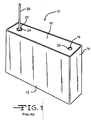
- FIG. 1 An example is shown in FIG. 1 . Whether the cell is of a primary or a secondary chemistry is not important.
- the casing 10 includes a planar front sidewall 12 opposite a planar back sidewall (not shown), both of which extend to and meet with a right end wall 14 and an opposed left end wall (not shown).
- the front and back sidewalls and the right and left end walls extend to and meet with a planar bottom wall (not shown) in a unitary construction to form a deep drawn container having an upper opening.
- the open ended container has a generally rectangular shape with the front and back sidewalls being parallel to each other and the right and left end walls being parallel to each other as well.
- An alternate construction is to provide individual plates which are connected together as sidewalls and end walls to form the open ended container.
- the open end of the container is closed by a generally planar lid 16.
- the lid 16 has a rectangular shape and is welded about its periphery to the upper edges of the respective sidewalls and end walls.
- the lid includes a fill opening 18 and a terminal pin opening 20.
- the fill opening 18 is a port for providing an electrolyte into the casing after an electrochemical couple is housed therein.
- the fill port is closed by a closure member 22, such as a ball, sealed therein.
- the terminal pin opening 20 supports a glass-to-metal seal comprising a ring of insulative glass 24 surrounding a terminal pin 26 having its interior end (not shown) connected to one of the anode and cathode housed inside the casing 10. That way, the terminal pin 26 serves as one of the cell leads.
- the prismatic shaped casing 10 is widely used for a variety of power source applications, there exists a need for cells that are of different shapes, such as those having a wedge shape in cross-section.
- the Vu et al. patent discloses a prismatic casing having partially contoured sidewalls.
- the casing includes opposed major side walls, one having a concave arc while the other has an opposed convex arc.
- the electrodes are disposed within the casing and deflected in a spring like manner to follow the arcs of the opposed sidewalls. That way, the casing maintains a positive pressure against the cell electrodes.
- the Probst et al. patent discloses an electrochemical cell housed in a casing of mating clamshell portions.
- the first clamshell portion has a first major sidewall extending to and meeting with a first surrounding sidewall and the second clamshell portion has a second major sidewall extending to and meeting with a second surrounding sidewall.
- the first and second clamshells are mated to each other with a first outer edge of the first surrounding sidewall facing the second major sidewall and a second outer edge of the second surrounding sidewall facing the first major sidewall. At least a portion of the first surrounding sidewall overlaps a portion of the second surrounding sidewall.
- the casing is then provided as a sealed enclosure with the first outer edge hermetically secured to the second surrounding sidewall.
- the first and second major sidewalls deflect in a similar direction.
- Probst et al. patent also describes a cell casing in which the opposed major sidewalls, even though they are curved, are not equidistant. In this patent, even though the back sidewall has a greater curvature than the front sidewall, the sidewalls curve in a similar direction. That type of casing construction is also not always desirable.
- the present invention provides a casing having a wedge-shape in which at least two directly opposed sidewalls angle away from each other.
- opposite sidewalls means a pair of sidewalls diametrically opposed to each other.
- the present invention is directed to an electrochemical cell of either a primary or a secondary, rechargeable chemistry housed in a generally wedge-shaped casing.
- the casing has a fronts sidewall, a back sidewall, a right end wall and a left end wall, all of them extending from a bottom wall to an open end closed by a lid.
- the wedge-shaped form factor is provided by the opposed right and left end walls having tapered widths. That is, the right and left end walls are wider near the top lid and narrower near the bottom wall.
- the spaced apart front and back sidewalls extending to and meeting with the opposed right and left end walls can either be planar or at least partly radiused to have a convex shape.
- a solid cathode enveloped in a separator is located intermediate the front and back anode portions and has a wedge shape characterized by a tapered width that generally corresponds to the taper of the right and left end walls.
- the front face of the front anode portion is parallel with the front major sidewall and the back face of the back anode portion is parallel with the back major sidewall.
- the present non-prismatic or wedge-shaped casing designs are particularly well suited for modern tools and devices requiring a self container power source provided with a "V-shaped" receptacle for the power source.
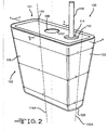
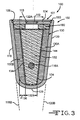
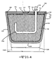
- FIGs. 2 to 4 illustrate one embodiment of an electrochemical cell 100 housed in a wedge-shaped casing 101 according to the present invention.
- This includes either an alkali metal/solid cathode or alkali metal/oxyhalide chemistry of both solid cathode and liquid electrolyte types.
- a solid cathode active material such as silver vanadium oxide or copper silver vanadium oxide, is contained within the casing and surrounded by a separator, such as of a polypropylene fabric or cloth. Lithium is the anode active material.
- the casing 101 comprises a wedge-shaped open-ended container 102 closed by a header comprising a lid 104.
- the container 102 and lid 104 are preferably of a conductive material selected from the group of nickel, aluminum, stainless steel, mild steel, tantalum, titanium, and combinations thereof. More preferably, the container 102 and lid 104 are of the same conductive material.
- the lid 104 has a generally rectangular shape with radiused corners and is secured about its periphery to the upper edges of the respective sidewalls and end walls comprising the container 102 by weld 106.
- the lid 104 includes a fill opening 108 and a terminal pin opening 110.
- the fill opening 108 is a port for providing an electrolyte into the casing 101 to activate an electrochemical couple housed therein.
- the port is closed by a closure member 112, such as the ball or plug, sealed therein by weld 113.
- the terminal pin opening 110 supports a glass-to-metal seal comprising a ring of insulative glass 114 surrounding a terminal pin 116 having its interior or proximal end 116A connected to one of the anode and cathode electrodes housed inside the casing 101. That way, the terminal pin 110 serves as one of the cell leads.
- the casing 101 insulated from the terminal pin 110 by the glass-to-metal seal 114 serves as the lead for the other electrode.
- the casing container 102 comprises front and back sidewalls 118, 120 extending to and meeting with right and left end walls 122 and 124, respectively.
- the wall pairs 118, 120 and 122, 124 are each in a non-parallel relationship with respect to each other.
- the wedge-shaped open-ended container 102 of the casing 101 comprises a generally planar, wedge-shaped front sidewall 118 opposite a generally planar, wedge-shaped back sidewall 120 ( FIG. 3 ), both of which extend to and meet with opposed generally planar wedge-shaped right and left end walls 122 and 124 ( FIG. 4 ) at radiused or curved corners.
- the wedge-shaped front and back sidewalls 118, 120 and the wedge-shaped right and left end walls 122, 124 extend in a unitary construction from an arcuate or curved bottom wall 126 to an open end.
- This provides the container 102 as a deep-drawn member having a generally trapezoidal, wedge shape with the front and back sidewalls 118, 120 and the right and left end walls 122, 124 forming respective pairs of walls that angle upwardly and outwardly with respect to each other along their entire extent from the bottom wall 126 to the open container end.
- An alternate construction is to provide individual plates which are connected together as sidewalls and end walls to form the trapezoidal, wedge shaped casing.
- this generally trapezoidal, wedge shape is shown by the distance between the edges of the end walls 122, 124 increasing moving in an upwardly direction from adjacent to the bottom wall 126 toward the open end.
- These non-uniform widths are shown by the relative distance "A” of end wall 122 adjacent to the bottom wall 126 being less than the distance "B” being less than the distance "C” adjacent to the open end of the container.
- that portion of the relative distances "A”, "B” and “C” on either side of an imaginary bisecting line 122A are substantially equal.
- the opposed end wall 124 is similarly shaped.
- the widths of the respective sidewalls 118, 120 increase moving in an upwardly direction from adjacent to the bottom wall 126 toward the open end. This is shown by the relative distance "X" of sidewall 118 adjacent to the bottom wall 126 being less than the distance "Y” being less than the distance "Z” adjacent to the open end of the container. Furthermore, that portion of the relative distances "X”, “Y” and “Z” on either side of an imaginary bisecting line 118A are substantially equal.
- the opposed sidewall 120 is similarly shaped. This angled relationship is shown by imaginary lines 118B and 120B projecting from the planar surface of the respective sidewalls 118, 120 meeting at a location below the bottom wall 126.
- a significant characterizing feature of the casing 101 is that the front and back major sidewalls 118, 120 are significantly wider at their maximum width than are the right and left end walls 122, 124.
- the thusly described casing 101 houses an electrode assembly comprising an anode 130 in electrical association with a cathode 132.
- the anode 130 and cathode 132 are physically segregated from contacting each other by an intermediate separator 134.
- the form of the anode 130 may vary, but preferably it comprises two portions 130A and 130B in the form of thin metal sheets or foils of anode active material, preferably lithium, pressed against the inner surface of the sidewalls 118, 120 serving as the anode terminal.
- the anode portions 130A, 130B can also comprise a perforated current collector (not shown), such as of nickel foil, having two sheets of anode active material, preferably lithium, pressed to its opposed major sides.
- Titanium, titanium alloy, copper, tungsten and tantalum are also suitable materials for the anode current collector.
- the anode current collector is then integrally contacted by a weld to an inner surface of the wedge-shaped sidewalls 118, 120 of the casing 100 serving as the anode terminal.
- the cathode 132 is of an electrically conductive material that serves as the other cell electrode.
- the cathode 132 is preferably of a solid cathode active material comprising a metal, a metal oxide, a mixed metal oxide and a metal sulfide, and combinations thereof.
- the cathode active material is formed by the chemical addition, reaction, or otherwise intimate contact of various metal oxides, metal sulfides or metal elements, preferably during thermal treatment, sol-gel formation, chemical vapor deposition or hydrothermal synthesis in mixed states.
- the active materials thereby produced contain metals, oxides and sulfides of Groups IB, IIB, IIIB, IVB, VB, VIB, VIIB and VIII, which include the noble metals and other oxide and sulfide compounds.
- a preferred cathode active material is a reaction product of at least silver and vanadium.
- the cathode 132 is a solid cathode active material such as silver vanadium oxide, carbon monofluoride (of, for example, a Li/CF x cell), or copper silver vanadium oxide, contained within the wedge-shaped casing 101 and physically segregated from the anode by the separator 134.
- Contemplated solid cathode active materials are not limited to silver vanadium oxide, carbon monofluoride, and copper silver vanadium oxide, but, can also be manganese dioxide, cobalt oxide, nickel oxide, copper oxide, copper sulfide, iron sulfide, iron disulfide, titanium disulfide, copper vanadium oxide, and mixtures thereof.
- the cathode active material is a silver vanadium oxide material as described in U.S. Patent Nos. 4,310,609 and 4,391,729 to Liang et al ., or copper silver vanadium oxide as described in U.S. Patent Nos. 5,472,810 and 5,516,340 to Takeuchi et al ., all assigned to the assignee of the present invention and incorporated herein by reference.
- the cathode active material is mixed with a conductive diluent and a binder material and the thusly formed active admixture is pressed into the desired shape.
- the cathode 132 is made from a mixture of 80 to 95 weight percent of a cathode active material, 1 to 10 weight percent of a conductive diluent and 3 to 10 weight percent of a binder.
- the binder is preferably a fluoro-resin powder such as polytetrafluoroethylene (PTFE), polyvinylidene fluoride (PVDF), polyethylene tetrafluoro ethylene (ETFE), polyamides, polyimides, and mixtures thereof. It is preferably used in a powdered form.
- Suitable conductive diluents include acetylene black, carbon black and/or graphite. Metals such as nickel, aluminum, titanium and stainless steel in powder form are also useful as conductive diluents when mixed with the above listed active materials.
- the cathode active mixture is contacted to a suitable current collector selected from titanium, titanium alloy, copper, tungsten, tantalum, and nickel. Titanium is a preferred material; however, if the cathode active material is CF x , the titanium current collector preferably has a coating of a graphite material on at least the surface contacted therewith.
- cathode 132 is at an intermediate location between the anode sheet portions 130A, 130B and is shaped to match the taper of the wedge-shaped casing 101.
- the cathode 132 enveloped in the separator 134 has an upper width 132A at a position nearest the lid 104 that is greater than its lower width 132B nearest the bottom wall 126.
- the taper of the cathode 132 matches that of the end walls 122, 124.
- the anode portions 130A, 130B have similar thicknesses 136 while their respective heights measured from adjacent to the bottom wall 126 to adjacent the lid 104 are equal or approximately equal to the height of the cathode 132. As shown in FIG.
- the anode 130 and the cathode 132 have similar widths adjacent to the lid 104, as indicated by arrow 138, and adjacent to the bottom wall 126, as indicated by arrow 140.
- Providing the anode portions 130A, 130B having essentially the same thicknesses and height as each other with the cathode 132 having a shape emulating the wedge-shaped casing 101 of the present invention minimizes the void (inactive) volume and maximizes the amount of active materials in the cell 100 having a non-traditional shaped, i.e. one that is neither prismatic or cylindrical.
- the anode 130 is physically segregated or separated from the cathode 132 by the separator 134.
- the separator 134 is an electrically insulative material that is chemically unreactive with the anode and cathode active materials.
- the separator 134 is also chemically unreactive with and insoluble in the electrolyte. Additionally, the separator material has sufficient porosity to allow flow therethrough of the electrolyte during the electrochemical reactions of the cell.
- Illustrative separator materials comprise fabrics woven from fluoropolymeric fibers including polyvinylidine fluoride, polyethylene tetrafluoro ethylene, and polyethylenechlorotrifluoroethylene used either alone or laminated with a fluoropolymeric microporous film, non-woven glass, polypropylene, polyethylene, glass fiber materials, ceramics, a polytetrafluoroethylene membrane commercially available under the designation ZITEX (Chemplast Inc.), a polypropylene membrane commercially available under the designation CELGARD (Celanese Plastic Company, Inc.) and a membrane commercially available under the designation DEXIGLAS (C.H. Dexter, Div., Dexter Corp.).
- fluoropolymeric fibers including polyvinylidine fluoride, polyethylene tetrafluoro ethylene, and polyethylenechlorotrifluoroethylene used either alone or laminated with a fluoropolymeric microporous film, non-woven glass, polypropy
- a preferred separator construction comprises a non-woven polypropylene fabric and polypropylene membrane.
- the non-woven fabric faces the cathode and the membrane faces the anode. That way, the non-woven layer acts as a wicking material to more effectively wet the cathode and act as a barrier to puncture of the membrane from loose cathode active materials such as carbon particles (CF x ).
- An insulator 160 is positioned between the lid 104 and the electrode assembly comprising the anode 130 and the cathode 132.
- the insulator 160 is a non-conductive material that securely positions the anode and cathode in the proper positions within the casing to obtain the desired battery capabilities.
- the thickness of the insulator 160 is shown exaggerated for purposes of illustration and it has an opening that allows an electrolyte filled into the casing 101 to contact the electrode assembly.
- the electrochemical cell 100 further includes a nonaqueous, ionically conductive electrolyte that serves as a medium for migration of ions between the anode 130 and the cathode 132 during the electrochemical reactions of the cell.
- the electrochemical reactions at the electrodes involve conversion of ions in atomic or molecular forms that migrate from the anode 130 to the cathode 132.
- suitable nonaqueous electrolytes are substantially inert to the anode and cathode materials, and they exhibit those physical properties necessary for ionic transport, namely, low viscosity, low surface tension and wettability.
- a suitable electrolyte has an inorganic, ionically conductive salt dissolved in a mixture of aprotic organic solvents comprising a low viscosity solvent and a high permittivity solvent.
- preferred lithium salts that are useful as a vehicle for transport of lithium ions from the anode 130 to the cathode 132 include LiPF 6 , LiBF 4 , LiAsF 6 , LiSbF 6 , LiClO 4 , LiO 2 , LiAlCl 4 , LiGaCl 4 , LiC(SO 2 CF 3 ) 3 , LiN(SO 2 CF 3 ) 2 , LiSCN, LiO 3 SCF 3 , LiC 6 F 5 SO 3 , LiO 2 CCF 3 , LiSO 6 F, LiB(C 6 H 5 ) 4 , LiCF 3 SO 3 , and mixtures thereof.
- Low viscosity solvents include esters, linear and cyclic ethers and dialkyl carbonates such as tetrahydrofuran (THF), methyl acetate (MA), diglyme, trigylme, tetragylme, dimethyl carbonate (DMC), 1,2-dimethoxyethane (DME), diethyl carbonate (DEC), and mixtures thereof
- high permittivity solvents include cyclic carbonates, cyclic esters and cyclic amides such as propylene carbonate (PC), ethylene carbonate (EC), acetonitrile, dimethyl sulfoxide, dimethyl formamide, dimethyl acetamide, ⁇ -valerolactone, ⁇ -butyrolactone (GBL), N-methylpyrrolidinone (NMP), and mixtures thereof.
- a preferred anode is lithium metal and the preferred electrolyte is 1.0M to 1.4M LiBF 4 in ⁇ -butyrolactone for a Li/CF x cell and a 1.0M to 1.2M LiAsF 6 or LiPF 6 in a 50:50, by volume, mixture of DME and PC.
- the cathode current collector (if present) is of titanium
- the terminal lead 116 is of molybdenum
- the electrolyte is a 1.0M to 1.4M solution of LiAsF 6 or LiPF 6 in a 50:50 mixture of, by volume, 1,2-dimethoxyethane and propylene carbonate
- the glass seal 114 is of TA-23 hermetic sealing glass
- closure 112 is of stainless steel.
- the lithium anode is preferable in sheet form contacted to both sides of a nickel foil current collector.
- the cell 100 can also be of a liquid cathode/electrolyte or catholyte type cell, for example a lithium-oxyhalide cell where a liquid catholyte fills the casing interior and is in operative contact with the anode 130 and the cathode element 132 is a carbonaceous material serving as a current collector.
- a separator 134 is disposed between the anode 130 and the carbonaceous cathode 132.
- the cell can also be of a secondary, rechargeable chemistry where the anode 130 comprises an anode material capable of intercalating and de-intercalating the anode active material, such as the preferred lithium.
- anode material capable of intercalating and de-intercalating the anode active material, such as the preferred lithium.
- a carbonaceous material comprising any of the various forms of carbon, e.g., coke, graphite, acetylene black, carbon black, glass carbon, meso-carbon microbeads (MCMB), and "hair carbon", which are capable of reversibly retaining the lithium species is preferred for the anode.
- "Hairy carbon” is a material described in U.S. Pat. No. 5,443,928 to Takeuchi et al ., which is assigned to the assignee of the present invention and incorporated herein by reference.
- Graphite is another preferred material. Regardless of the form of the carbon, fibers of the carbonaceous material are particularly advantageous because they have excellent mechanical properties which permit them to be fabricated into rigid electrodes that are capable of withstanding degradation during repeated charge/discharge cycling. Moreover, the high surface area of carbon fibers allows for rapid charge/discharge rates.
- the cathode 132 preferably comprises a lithiated material that is stable in air and readily handled.
- air-stable lithiated cathode active materials include oxides, sulfides, selenides, and tellurides of such metals as vanadium, titanium, chromium, copper, molybdenum, niobium, iron, nickel, cobalt and manganese.
- the more preferred oxides include LiNiO 2 , LiMn 2 O 4 , LiCoO 2 , LiCo 0.92 Sn 0.08 O 2 and LiCo 1-x Ni x O 2 .
- a preferred form of the electrochemical cell 100 is a case-negative design.
- a preferred material for the casing container 102 is titanium although stainless steel, mild steel, nickel, nickel-plated mild steel and aluminum are also suitable.
- the casing header comprising the metallic lid 104 is of a material similar to that of the container 101 and has a sufficient number of openings to accommodate the glass-to-metal seal/terminal pin feedthrough for the cathode 130. An additional opening is provided for the electrolyte.
- the casing 101 is thereafter filled with the electrolyte solution described hereinabove and hermetically sealed such as by close-welding the stainless steel closure member 112 into the fill hole or port 108, but not limited thereto.
- the cell 100 can also be constructed in a case-positive design, as is well known by those skilled in the art.
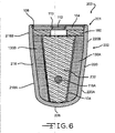
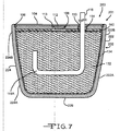
- FIGs. 5 to 7 illustrate another embodiment of an electrochemical cell 200 comprising a casing 201 according to the present invention.
- the casing 201 comprises a container 202 closed by a header comprising the lid 204 shown in FIGs. 2 to 4 .
- the casing container 202 comprises front and back sidewalls 218, 220 extending to and meeting with right and left end walls 222 and 224, respectively, at radiused or curved corners. At least some portions of the wall pairs 218, 220 and 222, 224 are in a non-parallel relationship with respect to each other.
- the wedge-shaped open-ended container 202 of the casing 201 comprises a compound planar, wedge-shaped front sidewall 218 opposite a compound planar, wedge-shaped back sidewall 220 ( FIG.
- the wedge-shaped front and back sidewalls 218, 220 and the wedge-shaped right and left end walls 222, 224 extend in a unitary construction from an arcuate or curved bottom wall 226 to an open end.
- This provides the container 202 as a deep-drawn member having a generally wedge shape with the front and back sidewalls 218, 220 and the right and left end walls 222, 224 forming respective pairs of walls that angle upwardly and outwardly with respect to each other along at least apportion of their lengths extending from the bottom wall 226 to the open container end.
- this wedge shape is shown by the relative distance "D" of end wall 222 adjacent to the bottom wall 226 being less than the distance "E” being substantially the same as the distance "F” adjacent to the open end of the container.
- the opposed end wall 224 is similarly shaped.
- the width of the sidewall 218 is shown by the relative distance "G” adjacent to the bottom wall 226 being less than the distance "H” being substantially the same as the distance "I” adjacent to the open end of the container.
- the opposed sidewall 220 is similarly shaped.
- a significant characterizing feature of the casing 201 is that the front and back major sidewalls 218, 220 are significantly wider at their maximum width than are the right and left end walls 222, 224.
- casing container 202 has wall pairs 218, 220 that comprise respective lower planar portions 218A, 220A that angle upwardly and outwardly with respect to each other and respective upper planar portions 218B, 220B that are substantially parallel to each other.
- the lower portions 218A, 220A account for the distances "G” being less that the distances "H” while the upper planar portions 218B and 220B account for the distances "H” being substantially the same as the distances "I”.
- the transition from the lower portions 218A, 220A to the upper portions 218B, 220B is curved or radiused. Furthermore, that portion of the relative distances "G", “H” and “I” on either side of an imaginary bisecting line 218C are substantially equal.
- the wall pairs 222, 224 comprise respective lower planar portions 222A, 224A and respective upper planar portions 222B, 224B.
- the lower portions 222A, 224A account for the distances "D" being less that the distances "E” while the upper planar portions 222B, 224B account for the distances "E” being substantially the same as the distances "F”.
- the transition from the lower portions 222A, 224A to the upper portions 222B, 224B is curved or radiused. Furthermore, that portion of the relative distances "D", "E” and “F” on either side of an imaginary bisecting line 222C are substantially equal.
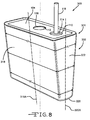
- FIG. 8 illustrates another embodiment of an electrochemical cell 300 comprising a casing 301 according to the present invention.
- the casing 301 comprises a container 302 closed by a header comprising the lid 104 shown in FIGs. 2 to 4 .
- the casing container 302 comprises front and back sidewalls 318, 320 extending to and meeting with right and left end walls 322 and 324, respectively, at radiused or curved corners.
- the wall pairs 318, 320 and 322, 324 are each in a non-parallel relationship with respect to each other.
- the wedge-shaped open-ended container 302 of the casing 301 comprises a generally planar rectangular-shaped front sidewall 318 opposite a generally planar rectangular-shaped back sidewall 320, both of which extend to and meet with opposed generally planar wedge-shaped right and left end walls 322 and 324.
- the rectangular-shaped front and back sidewalls 318, 320 and the wedge-shaped right and left end walls 322, 324 extend in a unitary construction from an arcuate or curved bottom wall 326 to an open end.
- This provides the container 302 as a deep-drawn member having a generally wedge shape with the front and back sidewalls 318, 320 and the right and left end walls 322, 324 forming respective wall pairs with only the sidewalls 318, 320 angling upwardly and outwardly with respect to each other along their entire extent from the bottom wall 326 to the open container end.
- the end walls 322, 324 are in a substantially parallel relationship with respect to each other.
- this wedge shape is shown by the relative distance "J" of end wall 322 adjacent to the bottom wall 326 being less than the distance "K” being less than the distance "L” adjacent to the open end of the container. Furthermore, that portion of the relative distances "J", “K” and “L” on either side of an imaginary bisecting line 322A are substantially equal.
- the opposed end wall 324 is similarly shaped.
- the widths of the respective sidewalls 318, 320 are shown by the relative distance "M" of sidewall 318 adjacent to the bottom wall 226 being substantially the same as the distance "N” being substantially the same as the distance “O” adjacent to the open end of the container. Furthermore, that portion of the relative distances "M”, “N” and “O” on either side of an imaginary bisecting line 318A are substantially equal.
- the opposed sidewall 320 is similarly shaped.
- a significant characterizing feature of the casing 301 is that the front and back major sidewalls 318, 320 are significantly wider at their maximum width than are the right left end walls 322, 324.
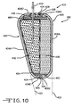
- FIGs. 9 and 10 illustrate another embodiment of an electrochemical cell 400 housed in a casing 402 having a wedge-shape according to the present invention.
- the wedge-shaped casing 402 includes a first or front clamshell portion 404 and a second or back clamshell portion 406 mated or otherwise secured to each other.
- the front clamshell 404 comprises a front major face wall 404A having a uniform width extending from adjacent a bottom portion of the casing to a lid portion.
- the lid portion includes a fill opening closed by a plug 408 and the terminal pin opening 410 supporting the glass-to-metal seal 412 and the terminal pin 414.
- the surrounding sidewall of the first clamshell extending from the front face wall 404A includes a right tapered end wall portion 404B, a left tapered end wall portion 404C, the right and left end wall portions 404B, 404C meeting a lid portion 404D and an arcuate bottom wall portion 404E.
- the wall portions 404B, 404C, 404D and 404E comprise the surrounding sidewall of the front clamshell 404 of the casing 402.
- the back clamshell 406 comprises a surrounding sidewall extending from the front face wall 406A.
- the surrounding sidewall includes a right end wall portion 406B, a left tapered end wall portion 406C, the right and left end wall portions 406B, 406C meeting a lid portion 406D and an arcuate bottom wall portion 406E.
- the wall portions 406B, 406C, 406D and 406E comprise the surround sidewall of the front clamshell 406 of the casing 402.
- a characterizing feature of the second clamshell portion 402 is that the wall portions 406B, 406C, 406D and 406E all have a similar height measured from where they meet the back face wall 406A to their distal edge.
- the height of the right and left end walls 404B, 404C of the first clamshell portion 404 having increasing heights measured from where they meet the front face wall 404A to their distal edges. This is illustrated by the combined widths of the right end wall portions 404B and 406B shown by,the relative distance "P" adjacent to the bottom wall portion 404E, 406E being less than their combined widths at intermediate location "Q” being less that their combined widths "R” adjacent to the lid portions 404D and 406D.
- the opposed left end wall portions 404C and 406C are similarly shaped.
- the non-right angling of front face wall 404A and the vertical orientation of the back face wall 406A are confirmed by comparing the imaginary line 420 projecting from the plane of front face wall 404A to the imaginary line 422 projecting from the back face wall 406A. These lines 420 and 422 intersect along the vertical path of the back face wall 406A.
- the clam shells may be butted together before they are sealed. This means that instead of the sidewall of one of the clamshells 404 or 406 being able to be partially housed or covered by the sidewall of the other clamshell, the sidewalls are of equal lengths and abut each other. The butted edges are sealed together such as by welding to form a hermetic enclosure.
- the front clamshell 404 has a front edge 424 and the back clamshell 406 has a back edge 426.
- the front edge 424 is relatively straight while the back edge 426 is a partial chicane shape (S-shaped) that receives the front edge 424.
- S-shaped partial chicane shape
- the respective front and back edges 424, 426 of the front and back clam shells 404, 406 are then secured to each other at hermetic seal 428.
- Other hermetic seals for mating clamshells are described in commonly assigned U.S. Patent No. 7,074,520 to Probst et al .
- this wedge-shape can be provided by a casing of the type described with respect to cells 100, 200 and 300. That is cells are housed in casing comprising a container closed by a lid, but having the shape shown with respect to cell 400.
- the seam between the clamshell portions would delineate one pair of major sidewalls or pair of end walls having one of the walls being in a vertical orientation while the other wall of the pair was in a angled relationship therewith. The included angle is acute.
- the electrode assembly housed inside the casing 402 includes an anode 430 positioned against the interior surface of the back clamshell 404 and a cathode 432 positioned against the front clamshell 404.
- a separator 434 completely envelopes the cathode 432 and maintains physical separation between the anode and cathode while providing for ionic flow therethrough.
- the cathode 432 is connected to the terminal pin 414 serving as the positive terminal electrically insulated from the casing by a glass-to-metal seal 436.
- the anode 430 is in direct contact with the casing 402 serving as the negative terminal in the case negative cell design.
- the anode can de provided in two portions on opposite side of an intermediate cathode in a similar manner as the electrode assembly described with respect to the cell 100 shown in FIGs. 2 to 4 .
- An insulator 460 preferably of a polymeric material, is provided as a ring-shaped member at an intermediate location between the weld 428 sealing the clamshell portion 404 and 406 together and the electrode assembly comprising the anode 430 and the cathode 432.
- the insulator 460 is for the purpose of preventing heat generated during the welding process from damaging the anode, cathode and separator 434.
- wedge-shape is characterized by at least one of the casing sidewalls being in a non-parallel relationship with a diametrically opposed sidewall. In some designs, both opposed sidewalls are in an angled alignment with respect to an imaginary vertical axis. In any event, such casing shapes are particularly useful where the cell is received in a "V-shaped" receptacle as may be demanded by modern tools and devices requiring a self container power source.
- the electrochemical cell comprises:
- the right and left end walls are parallel to each other.
- the front and back major sidewalls are significantly wider at their maximum width than are the right and left end walls.
- the first and third widths are the same.
- the second and fourth widths are the same.
- the front major sidewall has a fifth width near the lid and a sixth width less than the fifth width adjacent to the bottom wall
- the back major sidewall has a seventh width adjacent to the lid and a eighth width less than the seventh width adjacent to the bottom wall.
- the fifth and seventh widths are the same.
- the sixth width and the eighth width are the same.
- the front major sidewall has a fifth width near the lid, an intermediate sixth width less than the fifth width, and a seventh width less than the fifth and sixth widths adjacent to the bottom wall
- the back major sidewall has an eighth width adjacent to the lid, an intermediate ninth width less than the eight width, and a tenth width less than both the eighth and ninth widths, adjacent to the bottom wall.
- the fifth and sixth widths of the front major sidewall are substantially the same.
- the eighth and ninth widths of the back major sidewall are substantially the same.
- the right end wall has a fifth width near the lid, an intermediate sixth width less than the fifth width, and a seventh width less than the fifth and sixth widths adjacent to the bottom wall
- the left end wall has an eighth width adjacent to the lid, an intermediate ninth width less than the eight width, and a tenth width less than both the eighth and ninth widths, adjacent to the bottom wall.
- the fifth and sixth widths of the front major sidewall are substantially the same.
- the eighth and ninth widths of the back major sidewall are substantially the same.
- the pairs of the fifth and eighth widths, the sixth and ninth widths and the seventh and tenth widths are substantially the same.
- the front major sidewall has a first uniform width and the back major sidewall has a second uniform width, both extending from where they meet the bottom wall to a lid.
- the anode comprises a first anode portion and a second anode portion housed inside the casing with the cathode intermediate the first and second anode portions.
- the cathode has a wedge-shape substantially matching that of the right and left end walls.
- the front major sidewall resides in a plane that is not parallel to a plane of the back major sidewall, but in an angled relationship therewith.
- the front major sidewall, the back major sidewall, the right end wall, and the left end wall extend from the bottom wall and connect to each other at radiused corners in a unitary construction.
- the electrochemical cell comprises the features that
- the front portion of the right end wall and the front portion of the left end wall increase in width measured from the front major sidewall to an edge thereof as they extend from the front portion of the bottom wall to the front portion of the top wall of the front clamshell.
- the back portion of the bottom wall, the back portion of the right end wall, the back portion of the left end wall, and the back portion of the top wall forming the back clamshell are of a similar width extending from the back major sidewall to an edge therefore.
- another embodiment of the electrochemical cell comprises:
- the front and back major sidewalls are significantly wider at their maximum width than are the right and left end walls.
- the first and third widths are the same.
- the second and fourth widths are the same.
- the right end wall has a first uniform width and the left end wall has a second uniform width, both extending from where they meet the bottom wall to a lid.
- the front and back major sidewalls are parallel to each other.
- the anode comprises a first anode portion and a second anode portion housed inside the casing with the cathode intermediate the first and second anode portions.
- the cathode has a wedge-shape substantially matching that of the right and left end walls.
- the front major sidewall resides in a plane that is not parallel to a plane of the back major sidewall, but in an angled relationship therewith.
- the front major sidewall, the back major sidewall, the right end wall, and the left end wall extend from the bottom wall and connect to each other at radiused corners in a unitary construction.
- the invention also relates to a method for providing an electrochemical cell, said method comprising the steps of:
- the method includes the step of providing the right and left end walls being parallel to each other.
- the method includes the step of providing the front and back major sidewalls being significantly wider at their maximum width than are the right and left end walls.
- the method includes the step of providing the first and third widths being the same.
- the method includes the step of providing the second and fourth widths being the same.
- the method includes the step of providing the front major sidewall having a fifth width near the lid and a sixth width less than the fifth width adjacent to the bottom wall, and the back major sidewall having a seventh width adjacent to the lid and a eighth width less than the seventh width adjacent to the bottom wall.
- the method includes the step of providing the fifth and seventh widths being the same.
- the method includes the step of providing the sixth width and the eighth width being the same.
- the method includes the step of providing the front major sidewall having a fifth width near the lid, an intermediate sixth width less than the fifth width, and a seventh width less than the fifth and sixth widths adjacent to the bottom wall, and the back major sidewall having an eighth width adjacent to the lid, an intermediate ninth width less than the eight width, and a tenth width less than both the eighth and ninth widths adjacent to the bottom wall.
- the method includes the step of providing the fifth and sixth widths of the front major sidewall being substantially the same.
- the method includes the step of providing the eighth and ninth widths of the back major sidewall being substantially the same.
- the method includes the step of providing the pairs of the fifth and eighth widths, the sixth and ninth widths and the seventh and tenth widths being substantially the same.
- the method includes the step of providing the front major sidewall having a first uniform width and the back major sidewall having a second uniform width, both extending from where they meet the bottom wall to a lid.
- the method includes the step of providing the anode comprising a first anode portion and a second anode portion housed inside the casing with the cathode intermediate the first and second anode portions.
- the method includes the step of providing the cathode having a wedge-shape substantially matching that of the right and left end walls.
- the method includes the step of providing:
Landscapes
- Chemical & Material Sciences (AREA)
- Chemical Kinetics & Catalysis (AREA)
- Electrochemistry (AREA)
- General Chemical & Material Sciences (AREA)
- Sealing Battery Cases Or Jackets (AREA)
- Secondary Cells (AREA)
- Primary Cells (AREA)
Applications Claiming Priority (1)
| Application Number | Priority Date | Filing Date | Title |
|---|---|---|---|
| US95287907P | 2007-07-31 | 2007-07-31 |
Publications (2)
| Publication Number | Publication Date |
|---|---|
| EP2023423A2 true EP2023423A2 (fr) | 2009-02-11 |
| EP2023423A3 EP2023423A3 (fr) | 2011-03-16 |
Family
ID=40092046
Family Applications (1)
| Application Number | Title | Priority Date | Filing Date |
|---|---|---|---|
| EP08013771A Withdrawn EP2023423A3 (fr) | 2007-07-31 | 2008-07-31 | Pile électrochimique non prismatique |
Country Status (2)
| Country | Link |
|---|---|
| US (1) | US20090035652A1 (fr) |
| EP (1) | EP2023423A3 (fr) |
Families Citing this family (18)
| Publication number | Priority date | Publication date | Assignee | Title |
|---|---|---|---|---|
| CA2661469A1 (fr) * | 2008-04-11 | 2009-10-11 | Andre Foucault | Appareil de reeducation des jambes |
| US8405956B2 (en) * | 2009-06-01 | 2013-03-26 | Avx Corporation | High voltage electrolytic capacitors |
| US8605411B2 (en) | 2010-09-16 | 2013-12-10 | Avx Corporation | Abrasive blasted conductive polymer cathode for use in a wet electrolytic capacitor |
| US8514547B2 (en) | 2010-11-01 | 2013-08-20 | Avx Corporation | Volumetrically efficient wet electrolytic capacitor |
| US8259435B2 (en) | 2010-11-01 | 2012-09-04 | Avx Corporation | Hermetically sealed wet electrolytic capacitor |
| US9105401B2 (en) | 2011-12-02 | 2015-08-11 | Avx Corporation | Wet electrolytic capacitor containing a gelled working electrolyte |
| US9129747B2 (en) | 2012-03-16 | 2015-09-08 | Avx Corporation | Abrasive blasted cathode of a wet electrolytic capacitor |
| DE102012213577A1 (de) | 2012-08-01 | 2014-02-06 | Robert Bosch Gmbh | Gehäuse für eine Batterie, Batterie und Batterieanordnung |
| DE102012214443A1 (de) * | 2012-08-14 | 2014-02-20 | Robert Bosch Gmbh | Verspannen von Batteriezellen durch eine bombierte Ausgestaltung des Batteriegehäuses |
| GB2512481B (en) | 2013-03-15 | 2018-05-30 | Avx Corp | Wet electrolytic capacitor for use at high temperatures |
| GB2512486B (en) | 2013-03-15 | 2018-07-18 | Avx Corp | Wet electrolytic capacitor |
| EP3107584A1 (fr) * | 2014-02-19 | 2016-12-28 | Tetra Laval Holdings & Finance S.A. | Alimentation électrique |
| US20150280177A1 (en) * | 2014-03-28 | 2015-10-01 | Intel Corporation | Method for providing a sealing compound on a battery cell |
| US10109844B2 (en) * | 2016-11-02 | 2018-10-23 | Greatbatch Ltd. | Dual weld plug for an electrochemical cell |
| CN113764794B (zh) * | 2021-06-04 | 2023-06-06 | 广州倬粤电能科技有限公司 | 一种新型水平结构电池盒 |
| DE102021207360A1 (de) | 2021-07-12 | 2023-01-12 | Robert Bosch Gesellschaft mit beschränkter Haftung | Batteriezelle, Batteriezellenadapter, System mit Batteriezelle und Batteriezellenadapter, sowie Batteriemodulzellenhalter |
| CN114188639B (zh) * | 2021-12-17 | 2022-06-24 | 南京航空航天大学 | 一种复合材料模块化电池结构、装置及制备方法 |
| US12512274B2 (en) | 2022-08-26 | 2025-12-30 | KYOCERA AVX Components Corporation | Wet electrolytic capacitor containing a gelled working electrolyte |
Citations (11)
| Publication number | Priority date | Publication date | Assignee | Title |
|---|---|---|---|---|
| US4246327A (en) | 1979-10-01 | 1981-01-20 | Medtronic, Inc. | High energy-density battery system |
| US4310609A (en) | 1979-12-17 | 1982-01-12 | Wilson Greatbatch Ltd. | Metal oxide composite cathode material for high energy density batteries |
| US4391729A (en) | 1979-12-17 | 1983-07-05 | Wilson Greatbatch Ltd. | Metal oxide composite cathode material for high energy density batteries |
| US5443928A (en) | 1994-02-18 | 1995-08-22 | Wilson Greatbatch Ltd. | Carbon electrode for a nonaqueous secondary electrochemical cell |
| US5472810A (en) | 1993-03-17 | 1995-12-05 | W. Greatbatch Ltd. | Copper, silver, vanadium oxide composite cathode material for high energy density batteries |
| US5516340A (en) | 1993-03-17 | 1996-05-14 | Wilson Greatbatch Ltd. | Process for making a metal oxide composite cathode material for high energy density batteries |
| US5869205A (en) * | 1997-11-12 | 1999-02-09 | Eveready Battery Company, Inc. | Electrochemical cell having multiple anode compartments |
| US5958088A (en) | 1998-03-04 | 1999-09-28 | Duracell, Inc. | Prismatic cell construction |
| US6267790B1 (en) | 1998-03-18 | 2001-07-31 | Ntk Powerdex, Inc. | Treatment of conductive feedthroughs for battery packaging |
| US6831827B1 (en) | 2002-10-30 | 2004-12-14 | Wilson Greatbatch Technologies, Inc. | Universal family spacers for a battery electrical protection device |
| US7074520B2 (en) | 2001-07-19 | 2006-07-11 | Wilson Greatbatch Technologies, Inc. | Contoured casing of mating clamshell portions for an electrochemical cell |
Family Cites Families (16)
| Publication number | Priority date | Publication date | Assignee | Title |
|---|---|---|---|---|
| US3202600A (en) * | 1951-05-04 | 1965-08-24 | British Aluminium Co Ltd | Current conducting element for aluminum reduction cells |
| US3898097A (en) * | 1974-11-11 | 1975-08-05 | Anthony V Fraioli | Secondary power cell |
| US4469765A (en) * | 1983-03-04 | 1984-09-04 | Motorola, Inc. | Shock absorbing battery housing |
| YU122483A (en) * | 1983-06-02 | 1986-02-28 | Aleksandar Despic | Bipolar element of a chemical current source |
| US5015545A (en) * | 1990-01-03 | 1991-05-14 | General Motors Corporation | Method and apparatus for cooling an array of rechargeable batteries |
| US5250373A (en) * | 1991-09-10 | 1993-10-05 | Wilson Greatbatch Ltd. | Internal electrode and assembly method for electrochemical cells |
| ES2141764T3 (es) * | 1992-04-01 | 2000-04-01 | Moltech Invent Sa | Prevencion de la oxidacion de materiales carbonosos y otros a temperaturas elevadas. |
| US6224995B1 (en) * | 1997-03-06 | 2001-05-01 | Mitsubishi Chemical Corporation | Three dimensional free form battery apparatus |
| JP2001291499A (ja) * | 2000-04-06 | 2001-10-19 | Toyota Motor Corp | 組電池 |
| US6869710B2 (en) * | 2001-02-09 | 2005-03-22 | Evionyx, Inc. | Metal air cell system |
| US20020119368A1 (en) * | 2001-02-09 | 2002-08-29 | Tzeng George Tzong-Chyi | Anode structure for metal air electrochemical cells and method of manufacture thereof |
| US6610443B2 (en) * | 2001-03-19 | 2003-08-26 | Wilson Greatbatch Ltd. | One-piece header assembly for hermetic battery terminal feedthrough, fill and closure designs |
| WO2002093667A2 (fr) * | 2001-05-14 | 2002-11-21 | Reveo, Inc. | Accumulateur metal-air dans lequel sont incorpores des systemes d'isolement ionique |
| US6878482B2 (en) * | 2001-06-04 | 2005-04-12 | Evionyx, Inc. | Anode structure for metal air electrochemical cells |
| USD496331S1 (en) * | 2003-10-30 | 2004-09-21 | Nanma Manufacturing Co., Ltd | Battery box |
| USD528504S1 (en) * | 2005-10-31 | 2006-09-19 | Joseph Bobbin | Battery housing |
-
2008
- 2008-07-28 US US12/180,860 patent/US20090035652A1/en not_active Abandoned
- 2008-07-31 EP EP08013771A patent/EP2023423A3/fr not_active Withdrawn
Patent Citations (11)
| Publication number | Priority date | Publication date | Assignee | Title |
|---|---|---|---|---|
| US4246327A (en) | 1979-10-01 | 1981-01-20 | Medtronic, Inc. | High energy-density battery system |
| US4310609A (en) | 1979-12-17 | 1982-01-12 | Wilson Greatbatch Ltd. | Metal oxide composite cathode material for high energy density batteries |
| US4391729A (en) | 1979-12-17 | 1983-07-05 | Wilson Greatbatch Ltd. | Metal oxide composite cathode material for high energy density batteries |
| US5472810A (en) | 1993-03-17 | 1995-12-05 | W. Greatbatch Ltd. | Copper, silver, vanadium oxide composite cathode material for high energy density batteries |
| US5516340A (en) | 1993-03-17 | 1996-05-14 | Wilson Greatbatch Ltd. | Process for making a metal oxide composite cathode material for high energy density batteries |
| US5443928A (en) | 1994-02-18 | 1995-08-22 | Wilson Greatbatch Ltd. | Carbon electrode for a nonaqueous secondary electrochemical cell |
| US5869205A (en) * | 1997-11-12 | 1999-02-09 | Eveready Battery Company, Inc. | Electrochemical cell having multiple anode compartments |
| US5958088A (en) | 1998-03-04 | 1999-09-28 | Duracell, Inc. | Prismatic cell construction |
| US6267790B1 (en) | 1998-03-18 | 2001-07-31 | Ntk Powerdex, Inc. | Treatment of conductive feedthroughs for battery packaging |
| US7074520B2 (en) | 2001-07-19 | 2006-07-11 | Wilson Greatbatch Technologies, Inc. | Contoured casing of mating clamshell portions for an electrochemical cell |
| US6831827B1 (en) | 2002-10-30 | 2004-12-14 | Wilson Greatbatch Technologies, Inc. | Universal family spacers for a battery electrical protection device |
Also Published As
| Publication number | Publication date |
|---|---|
| EP2023423A3 (fr) | 2011-03-16 |
| US20090035652A1 (en) | 2009-02-05 |
Similar Documents
| Publication | Publication Date | Title |
|---|---|---|
| EP2023423A2 (fr) | Pile électrochimique non prismatique | |
| US6635381B2 (en) | Electrochemical lithium ion secondary cell having a scalloped electrode assembly | |
| US6586131B2 (en) | Apparatus for releasing gases from rechargeable lithium electrochemical cells during the formation stage of manufacturing | |
| US10170744B2 (en) | Electrochemical current collector screen designs utilizing ultrasonic welding | |
| US6641953B2 (en) | Secondary cell with high rate pulse capability | |
| EP1496562A1 (fr) | Accumulateur d'electrolyte non aqueux | |
| US6541140B1 (en) | Electrochemical lithium ion secondary cell having multiplate electrodes with differing discharge rate regions | |
| JP2000348768A (ja) | 再充電可能な電気化学電池における非水性電解液のための硝酸エステル添加剤 | |
| JP2000294282A (ja) | 非水性電解液の再充電可能な電池のための亜硫酸塩添加剤 | |
| JP5173095B2 (ja) | 密閉型電池 | |
| US11670816B2 (en) | Glass-to-metal seal terminal pin for an electrochemical cell | |
| JP2002198092A (ja) | 非水性電解液再充電可能な電池のホスフェート添加剤 | |
| US7022146B2 (en) | Method for providing a hermetically sealed coin cell | |
| US6623884B1 (en) | Electrochemical lithium ion secondary cell having multiplate and jellyroll electrodes with differing discharge rate regions | |
| US9300007B1 (en) | Ultrasonic welding of lithium onto a current collector | |
| US11114661B2 (en) | Electrochemical cell having a serpentine anode with a plurality of interleaved cathode plates having extending tabs stacked and connected to each other by a welded surrounding metal hoop | |
| US20140087239A1 (en) | Hermetic coin cell-type assemblies | |
| EP3958345A1 (fr) | Module de batterie | |
| JP2009205864A (ja) | 非水電解質電池 | |
| JP2000133306A (ja) | 非水性電解液の再充電可能な電池のための有機カ―ボネ―ト添加剤 | |
| EP4683054A1 (fr) | Cellule électrochimique et son procédé de fourniture | |
| EP4307409A1 (fr) | Joint élastomère en contact avec la surface interne du couvercle de boîtier d'une cellule électrochimique au lithium à décharge par impulsions | |
| JP4055395B2 (ja) | 密閉型電池 | |
| EP3806181B1 (fr) | Accumulateur, et batterie |
Legal Events
| Date | Code | Title | Description |
|---|---|---|---|
| PUAI | Public reference made under article 153(3) epc to a published international application that has entered the european phase |
Free format text: ORIGINAL CODE: 0009012 |
|
| AK | Designated contracting states |
Kind code of ref document: A2 Designated state(s): AT BE BG CH CY CZ DE DK EE ES FI FR GB GR HR HU IE IS IT LI LT LU LV MC MT NL NO PL PT RO SE SI SK TR |
|
| AX | Request for extension of the european patent |
Extension state: AL BA MK RS |
|
| PUAL | Search report despatched |
Free format text: ORIGINAL CODE: 0009013 |
|
| AK | Designated contracting states |
Kind code of ref document: A3 Designated state(s): AT BE BG CH CY CZ DE DK EE ES FI FR GB GR HR HU IE IS IT LI LT LU LV MC MT NL NO PL PT RO SE SI SK TR |
|
| AX | Request for extension of the european patent |
Extension state: AL BA MK RS |
|
| 17P | Request for examination filed |
Effective date: 20110831 |
|
| AKX | Designation fees paid |
Designated state(s): DE FR |
|
| STAA | Information on the status of an ep patent application or granted ep patent |
Free format text: STATUS: THE APPLICATION HAS BEEN WITHDRAWN |
|
| 17Q | First examination report despatched |
Effective date: 20120615 |
|
| 18W | Application withdrawn |
Effective date: 20120702 |