EP2023463A2 - Luminaire d'urgence - Google Patents
Luminaire d'urgence Download PDFInfo
- Publication number
- EP2023463A2 EP2023463A2 EP07118935A EP07118935A EP2023463A2 EP 2023463 A2 EP2023463 A2 EP 2023463A2 EP 07118935 A EP07118935 A EP 07118935A EP 07118935 A EP07118935 A EP 07118935A EP 2023463 A2 EP2023463 A2 EP 2023463A2
- Authority
- EP
- European Patent Office
- Prior art keywords
- circuit
- voltage
- converter
- output
- battery
- Prior art date
- Legal status (The legal status is an assumption and is not a legal conclusion. Google has not performed a legal analysis and makes no representation as to the accuracy of the status listed.)
- Withdrawn
Links
Images


Classifications
-
- H—ELECTRICITY
- H05—ELECTRIC TECHNIQUES NOT OTHERWISE PROVIDED FOR
- H05B—ELECTRIC HEATING; ELECTRIC LIGHT SOURCES NOT OTHERWISE PROVIDED FOR; CIRCUIT ARRANGEMENTS FOR ELECTRIC LIGHT SOURCES, IN GENERAL
- H05B41/00—Circuit arrangements or apparatus for igniting or operating discharge lamps
- H05B41/14—Circuit arrangements
- H05B41/26—Circuit arrangements in which the lamp is fed by power derived from DC by means of a converter, e.g. by high-voltage DC
- H05B41/28—Circuit arrangements in which the lamp is fed by power derived from DC by means of a converter, e.g. by high-voltage DC using static converters
- H05B41/295—Circuit arrangements in which the lamp is fed by power derived from DC by means of a converter, e.g. by high-voltage DC using static converters with semiconductor devices and specially adapted for lamps with preheating electrodes, e.g. for fluorescent lamps
- H05B41/298—Arrangements for protecting lamps or circuits against abnormal operating conditions
- H05B41/2988—Arrangements for protecting lamps or circuits against abnormal operating conditions for protecting the lamp against abnormal operating conditions
Definitions
- This invention is related to a type of emergency luminaire, specifically speaking, is related to an easily-installed emergency device which can be used to prolong the service life of the fluorescent lamp.
- the emergency luminaire both at home and abroad are loaded by fluorescent lamp.
- the installation of the device is complex for the fluorescent lamp has to be mated with ballast and inverter.
- the high-frequency and high-voltage AC power shifted from the battery by inverter is directly connected with the two ends of the fluorescent lamp.
- the fluorescent lamp will emit light after being punctured by high voltage. Since the fluorescent lamp does not start up and work in the matching state, the two ends of the bulb become dark quickly and the filament is easily broken. This largely shortens the service life of the fluorescent lamp.
- this invention is concerned with designing an electronic circuit with complete functions, using the most basic and easiest electronic components. It intends to convert AC into DC with electronic circuit in the interests of lightening the weight of the product and reducing the heat generated. Another feature of this new practical invention is that it simplifies the installation and maintenance program as well as increases the maintenance efficiency.
- This new practical device provides an emergency luminaire which includes the case made up of front cover, back cover and electronic circuit.
- the electronic circuit fixed on the interior side of the back cover, is comprised of an AC-DC converter, a charging circuit, a control circuit, a DC-DC converter, a DC-AC converter, an output AC-DC converter and a conversion circuit:
- the electronic circuit board is installed with many plug terminals connected respectively with power line, test switch, charging indicator, discharging indicator, rechargeable battery and electronic ballast.
- the input AC-DC circuit also includes over-current and over-voltage protection circuits made up of fuses in series or parallel connection with the Input end of the AC as well as varistors.
- the input AC-DC circuit also includes anti-interference circuit composed of capacitances in series or parallel connection with the input end of the AC and common-mode Inductances. This is used to eliminate the mutual interference between AC and post-circuit.
- the input AC-DC also includes AC automatic detecting circuit made up of a triode and three divider resistances and capacitances in series, which is connected with the two ends of the rectification circuit in the input AC-DC circuit.
- the charging circuit also includes:
- the charging display circuit used to indicate the charging condition of the battery.
- the emergency luminaire mentioned in the present invention also includes:
- the battery abnormity over-current protection is completed by the recoverable over-current fuse.
- the emergency luminaire mentioned in the present invention also includes:
- the emergency luminaire in the present invention features high efficiency, powerful functions, low power consumption, long service life of the fluorescent lamp and convenient installation.
- the present invention is simple in structure and convenient to fix. Comparing to the ordinary emergency luminaire, it reduces more than 1/3 of the assembly connection.
- the emergency output in the present invention directly affects the electronic ballast so that the fluorescent lamp can work in the matching state. Comparing to the ordinary emergency luminaire, it can prolong the service life of the fluorescent lamp for several dozens of times. Comparing to the ordinary emergency luminaire, the present invention possesses even more perfect functions. For example, it is provided with charging over-current and over-discharge protection for the rechargeable battery, discharge over-current protection circuit, AC under-voltage protection, charging and discharging indicator, and integrated testing function.
- the device in the present invention is loaded by electronic ballast, which makes the assembly extremely easy and minimizes the number of the assembly connection used.
- the emergency output is high voltage direct current and is directly connected with the input terminal of electronic ballast. In emergency, the electric power of the fluorescent lamp is supplied by the original electronic ballast for this will bring the fluorescent lamp under the best working condition; thus the service life of the fluorescent lamp can be maximized.
- the emergency luminaire in an implementation example of this invention include the case.
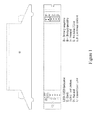
- Figure 1 is the diagram of the case of this emergency luminaire.
- This case comprises front cover (11), back cover (12), battery (13) (not showed in the Figure), and electronic circuit board (not showed in the Figure).
- the electronic circuit inside the emergency luminaire for energy-saving lights is started up.
- the electronic ballast (not showed in the Figure) and the fluorescent lamp (not showed in the Figure) connected with the output terminal start to emit light.
- the electronic circuit board is the core component and the control function of the case. It is fixed on back cover (12) by bolts and is covered with front cover (11), leaving only the input and output plug terminals which are connected respectively with charging and discharging indicators, safety ground lead, test switch, N line, U line (L line not connected with control switch), L line (connected with control switch), battery and interface of the electronic ballast.
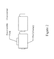
- Figure 2 is the installation structure diagram of recoverable over-current fuse and battery; the battery can be damaged when it is short-Circuited or faces other abnormal situations which will cause a large-current discharge.
- Recoverable over-current fuse can disconnect to protect the battery when a large-current discharge takes place; it can also come back to the normal state after the breakdown is excluded.
- Figure 3 is the interior circuit diagram of the electronic circuit board of the emergency luminaire in the present invention. It includes the input AC-DC converter diagram, the charge-circuit diagram; the control circuit diagram; the charging and discharging indicator circuit; the DC-AC converter diagram; the output AC-DC converter diagram; and the converter diagram. The specific explanations of these circuits are given with Figures as follows:
- Figure 4 is the input AC-DC converter diagram.
- the input AC-DC converter part of the circuit adopts a new type of switching power supply featuring high efficiency of conversion, stable working condition, wide range of application voltage, and protection of under-voltage.
- it can substitute the traditional power transformer component which is low in conversion efficiency and working stability, and narrow in the range of application voltage.
- the 220V AC is commutated by the rectifier bridge A1.
- the 220V unstable direct voltage was produced after the power factor correction circuit made up of diodes D3, D4 and D5 and capacitances C3 and C4 is filtered;
- Tube fuse FU is connected in series with the input terminal of the 220V AC for over-current protection;
- Varistor VR1 and FU comprise the over-voltage and over-current protection circuit of the AC.
- the common mode L1 connected in series with and C1 and C2 connected in parallel with the 220V AC is used to eliminate the mutual interference between AC and post-Circuit; resistances R2 and R3 are the starting-resistor of integrated circuit IC1.
- the induced voltage on the secondary coil of transformer Ts1 is converted to two groups of DC after commutated by diode D2 and D7 and then filtered by capacitances C8 and C9; one group charges the battery through diode D6; the other is fed to the control circuit with test switch TEST.
- the voltage induced on the secondary coil of transformer Ts2 is commutated through switching diode D13, filtered through C12 and then is fed on the control terminal C through photoelectric coupler A2; IC2, the voltage reference, tests the output voltage through resistances R11 and R12 to compare with the reference voltage 1.25V; when the direct voltage charging the battery rises, the current of the photoelectric coupler A2 flowed through photodiode increases and intensifies the conduction of the photosensitized receiving device through the photoelectric coupler A2.
- the output pulse length of IC1 becomes narrowing and is coupled through transformer to the secondary coil Ts1 in order to make the output voltage decrease, and vice versa, namely when the output voltage rises, the pulse length is made to be narrowing though feedback in order to make the output voltage decrease; when the output voltage decreases, the pulse length is made to be widening though feedback in order to make the output voltage rise. All is to guarantee the stabilizing of the output voltage.
- Capacitances C13, C14 and C15 are anti-interference capacitance.
- the resistance R7 and the capacitance C5 are soft-start circuits.
- the C voltage of IC1 rises slowly for it has to charge C5 in order to reduce the impact to IC1 during starting.
- Detector switch TEST the status-detect switch of the emergency luminaire in the present invention, is for the use of testing the switch between normal lighting and emergency lighting.
- AC is normal, the test switch is switched on.
- the emergency luminaire is being charged and the energy of the fluorescent lamp is provided by electronic ballast. Now switch off the test switch. Because AC is still fed to the Input end of the emergency luminaire for energy-saving light, it is still charging.
- the control circuit switches by reason of the power cut, and thus batteries change the circuit by DC-AC and output AC-DC to form a high voltage direct current which provides the fluorescent lamp with lighting power through electronic ballast.
- FIG. 5 is the current-limited charging circuit diagram. This circuit is made up of resistance R8 and triode V4. While the battery is being charged, the current flowed through R1 forms a voltage drop on R1. When the current increases and the voltage drop reaches 0.6V as a result, V4 is saturated and conducted, IC2 becomes a short circuit and the current flowed through the photoelectric coupler A1 increases. Then with the help of feedback circuit, the output pulse length of IC1 is made to be narrowing and the output voltage decreases. Sequentially the increase of charge current is curbed.
- Figure 6 is the control circuit diagram; When AC is normal, the direct voltage on the control circuit is shared by R13 and R17 and is fed on the base of triode V6 in order to make V6 saturated and conducted; then the base voltage of triode V7 is 0V and the voltage connected with the base of triode V7 through resistance R23 does not take effect.
- Relay RYL does not work, the battery voltage cannot be connected with B3 through the normal open contact of the relay, and DC-AC circuit does not work for short of power.
- Capacitance C11 and diode D15 make up the protection circuit of relay RYL.
- This voltage is divided by resistances R14, R25 and resistance R24 in order to maintain the continuous saturation and conduction of triode V7; at the same time, it provides power to DC-AC circuit through diode D14. Adjusting the resistance value of resistances R14, R24 and R25 can force triode V7 to stop working under different voltages in order to achieve the over-discharge protection of the battery as well as to avoid the damage of the battery from over-discharge.
- Figure 7 is the charging and discharging indicator circuit.
- the direct voltage formed after commutated through diode D2 and then filtered through capacitance C8 is larger than the breakdown voltage of stable diode D16, so stable diode D16 is conducted; direct voltage is fed on the base of triode V5 with stable diode D16 and current-limiting resistance R15 in order to make triode V5 saturated and conducted.
- the collector voltage of triode V5 is 0V; light-emitting diode D17-G does not work for short of power, and it shows battery unconnected.
- the direct voltage formed after commutated through diode D2 and then filtered through capacitance C8 is far less than the breakdown voltage of stable diode D16 so that stable diode D16 is closed.
- the base of triode V5 is powerless so that Triode V5 is closed.
- the collector voltage of triode V5 keeps the high level; light-emitting diode D17-G starts to emit light with power, and it shows battery connected; the resistance value of adjusting resistance R15 can change the light brightness of D17-G.
- the control circuit acts, B2 gets power from relay RYL, and the normal open contact gets power after turning on and is fed on light-emitting diode D17-R through current-limiting resistance R22; light-emitting diode D17-R starts to emit light with power and shows the discharge is in progress.
- the resistance value of adjusting resistance R22 can change the light brightness of light-emitting diode D17-R.
- FIG 8 is the DC-AC converter diagram.
- Triodes V1 and V2 make up the current-feedback push-pull oscillator; resistances R18, R19, R20 and R21 make up the start circuit; the battery voltage is fed on the center tap point of transformer L5 through Inductance L4.
- the control circuit acts, relay RYL gets power, the normal open contact is turned on, and the battery gets power from B2 through the normal open contact; diode D14, start resistances R18, R19, R20 and R21 trigger the oscillator to work and drive triodes V1 and V2 is driven to work and conducted alternatively; sinusoidal waveform high-frequency AC is formed at E1 and E2, both ends of the secondary coil of transformer.
- This circuit can still work continuously when loading changing or even open circuit. Adjusting the resistance value of resistances R18, R19, R20 and R21 as well as the parameter of transformer L5 can change the output voltage and
- Figure 9 is the input AC-DC converter diagram. It is to convert high-frequency and high-voltage AC into high-voltage DC. When AC is powered off, or the test switch is turned off or the input AC-DC converter in Figure 4 is under-voltage protection action, the control circuit acts.
- Figure 8 is the output high-frequency and high-voltage AC of DC-AC Converter. It becomes DC after flowing through the bridge rectifier circuit made up of diodes D9, D10, D11 and D12.
- Capacitance C10 is filtering capacitance. It is used to smooth the ripple of DC.
- Varistor VR2 can absorb the spike voltage and limit the maximum direct voltage in order to convert the output DC to the DC within the applicable voltage range of electronic ballast.
- Figure 10 is the converter circuit.
- relay RYL When AC is normal, relay RYL does not work, and the normal open contact is turned on.
- Line L in AC is connected with the normal closed contact (non-common end) of relay through control switch K and then is connected with terminal L of the input terminal of electronic ballast through the normal closed contact;
- Line N in AC is directly connected with terminal N of electronic ballast; electronic ballast starts to work with power; the fluorescent lamp emits light.
- the emitting of fluorescent lamp is controlled by electronic ballast and the bulb is mated with electronic ballast, so the service life of the bulb can be maximized. Comparing to the ordinary emergency luminaire, it can prolong the service life of the fluorescent lamp for several dozens of times.
Landscapes
- Circuit Arrangement For Electric Light Sources In General (AREA)
- Circuit Arrangements For Discharge Lamps (AREA)
Applications Claiming Priority (1)
| Application Number | Priority Date | Filing Date | Title |
|---|---|---|---|
| CNU2007201266898U CN201069088Y (zh) | 2007-08-06 | 2007-08-06 | 一种应急照明装置 |
Publications (2)
| Publication Number | Publication Date |
|---|---|
| EP2023463A2 true EP2023463A2 (fr) | 2009-02-11 |
| EP2023463A3 EP2023463A3 (fr) | 2010-11-17 |
Family
ID=39490475
Family Applications (1)
| Application Number | Title | Priority Date | Filing Date |
|---|---|---|---|
| EP07118935A Withdrawn EP2023463A3 (fr) | 2007-08-06 | 2007-10-19 | Luminaire d'urgence |
Country Status (2)
| Country | Link |
|---|---|
| EP (1) | EP2023463A3 (fr) |
| CN (1) | CN201069088Y (fr) |
Cited By (8)
| Publication number | Priority date | Publication date | Assignee | Title |
|---|---|---|---|---|
| DE102009044593A1 (de) * | 2009-11-19 | 2011-05-26 | Vossloh-Schwabe Deutschland Gmbh | Betriebssteuergerät zum Betreiben eines Leuchtmittels |
| CN105244997A (zh) * | 2015-10-30 | 2016-01-13 | 国家电网公司 | 一种采集终端双电源切换装置 |
| EP2856846A4 (fr) * | 2012-05-30 | 2016-04-20 | Fulham Co Ltd | Ballast avec batterie de secours |
| CN107834648A (zh) * | 2017-11-21 | 2018-03-23 | 江门市天王达科技实业有限公司 | 一种应用于应急照明灯具的充电电路及其方法 |
| CN108110860A (zh) * | 2018-01-26 | 2018-06-01 | 重庆科技学院 | 基于高电压低电流电能的蓄电放电装置 |
| CN110769560A (zh) * | 2019-12-03 | 2020-02-07 | 深圳市廿年科技有限公司 | 一种通过mcu控制实现led灯渐亮的控制电路 |
| CN112350423A (zh) * | 2020-11-04 | 2021-02-09 | 合肥联信电源有限公司 | 一种具有冗余电源的应急照明控制器 |
| CN112798985A (zh) * | 2019-10-28 | 2021-05-14 | 上海度普新能源科技有限公司 | 一种电池包电压线序检测电路 |
Families Citing this family (11)
| Publication number | Priority date | Publication date | Assignee | Title |
|---|---|---|---|---|
| US8274227B2 (en) * | 2010-05-06 | 2012-09-25 | Nextek Power Systems, Inc. | High-efficiency DC ballast arrangement with automatic polarity protection and emergency back-up for lighting fixture in a suspended DC-powered ceiling system |
| CN101915378B (zh) * | 2010-06-28 | 2013-04-24 | 海洋王照明科技股份有限公司 | 一种防爆标志灯 |
| CN102111936B (zh) * | 2010-11-26 | 2013-07-17 | 深圳市聚作照明股份有限公司 | Led驱动电源 |
| WO2013063761A1 (fr) * | 2011-11-01 | 2013-05-10 | 深圳市讯宇创科技有限公司 | Circuit et système de lampe d'éclairage de sécurité |
| CN103179719B (zh) * | 2011-12-20 | 2015-03-18 | 海洋王照明科技股份有限公司 | 一种led应急照明转换电路及应急灯 |
| CN102520297A (zh) * | 2011-12-30 | 2012-06-27 | 山东省产品质量监督检验研究院 | 消防应急照明及疏散指示系统移动式综合检测装置 |
| CN105262205A (zh) * | 2015-10-30 | 2016-01-20 | 国家电网公司 | 采集终端双电源切换控制电路 |
| CN106793368B (zh) * | 2016-11-07 | 2023-06-02 | 合肥东泰工贸有限公司 | 两线式应急照明逆变电源装置 |
| CN110657358B (zh) * | 2019-10-09 | 2021-08-24 | 汕头市德杰电子有限公司 | 一种应急照明灯 |
| CN110602835B (zh) * | 2019-10-17 | 2024-09-20 | 上海芯荃微电子科技有限公司 | 一种利用开关控制应急照明灯具充电的电路及方法 |
| CN116914893B (zh) * | 2023-09-12 | 2024-02-09 | 深圳市凌鑫电子有限公司 | 锂电池放电控制电路 |
Family Cites Families (6)
| Publication number | Priority date | Publication date | Assignee | Title |
|---|---|---|---|---|
| GB2016223B (en) * | 1978-02-09 | 1982-11-03 | Maylectro Ltd | Emergency lighting |
| US6933627B2 (en) * | 1991-01-08 | 2005-08-23 | Nextek Power Systems Inc. | High efficiency lighting system |
| JPH0698482A (ja) * | 1992-06-10 | 1994-04-08 | Digital Equip Corp <Dec> | 電力供給装置 |
| EP1099292A1 (fr) * | 1998-10-30 | 2001-05-16 | Lumatec SA | Element lumineux de secours pour actionner des lampes fluorescentes en cas de panne de secteur |
| DE102004035678A1 (de) * | 2004-07-22 | 2006-03-16 | Patent-Treuhand-Gesellschaft für elektrische Glühlampen mbH | Notlichtvorschaltelement mit digital adressierbarer Steuerschnittstelle |
| US20060120073A1 (en) * | 2004-12-06 | 2006-06-08 | Pickard Paul K | Emergency ballast |
-
2007
- 2007-08-06 CN CNU2007201266898U patent/CN201069088Y/zh not_active Expired - Fee Related
- 2007-10-19 EP EP07118935A patent/EP2023463A3/fr not_active Withdrawn
Cited By (12)
| Publication number | Priority date | Publication date | Assignee | Title |
|---|---|---|---|---|
| DE102009044593A1 (de) * | 2009-11-19 | 2011-05-26 | Vossloh-Schwabe Deutschland Gmbh | Betriebssteuergerät zum Betreiben eines Leuchtmittels |
| DE102009044593B4 (de) * | 2009-11-19 | 2018-07-12 | Vossloh-Schwabe Deutschland Gmbh | Betriebssteuergerät zum Betreiben eines Leuchtmittels |
| EP2856846A4 (fr) * | 2012-05-30 | 2016-04-20 | Fulham Co Ltd | Ballast avec batterie de secours |
| US9954390B2 (en) | 2012-05-30 | 2018-04-24 | Fulham Co., Ltd. | Ballast with battery backup |
| CN105244997A (zh) * | 2015-10-30 | 2016-01-13 | 国家电网公司 | 一种采集终端双电源切换装置 |
| CN107834648A (zh) * | 2017-11-21 | 2018-03-23 | 江门市天王达科技实业有限公司 | 一种应用于应急照明灯具的充电电路及其方法 |
| CN108110860A (zh) * | 2018-01-26 | 2018-06-01 | 重庆科技学院 | 基于高电压低电流电能的蓄电放电装置 |
| CN108110860B (zh) * | 2018-01-26 | 2023-10-20 | 重庆科技学院 | 基于高电压低电流电能的蓄电放电装置 |
| CN112798985A (zh) * | 2019-10-28 | 2021-05-14 | 上海度普新能源科技有限公司 | 一种电池包电压线序检测电路 |
| CN112798985B (zh) * | 2019-10-28 | 2022-07-26 | 上海度普新能源科技有限公司 | 一种电池包电压线序检测电路 |
| CN110769560A (zh) * | 2019-12-03 | 2020-02-07 | 深圳市廿年科技有限公司 | 一种通过mcu控制实现led灯渐亮的控制电路 |
| CN112350423A (zh) * | 2020-11-04 | 2021-02-09 | 合肥联信电源有限公司 | 一种具有冗余电源的应急照明控制器 |
Also Published As
| Publication number | Publication date |
|---|---|
| EP2023463A3 (fr) | 2010-11-17 |
| CN201069088Y (zh) | 2008-06-04 |
Similar Documents
| Publication | Publication Date | Title |
|---|---|---|
| EP2023463A2 (fr) | Luminaire d'urgence | |
| CN110536506B (zh) | Led频闪爆闪电路 | |
| CN205489733U (zh) | 一种基于单片机控制的充电器 | |
| CN104093245A (zh) | 一种高效隔离式led驱动电路 | |
| CN100554975C (zh) | 一种长时效张弛振荡闪光型高压带电显示器的电路结构 | |
| CN111343759B (zh) | Led驱动电路、灯管和照明装置 | |
| KR20140142134A (ko) | 형광등 안정기에 연결되어 구동하는 led형광등 구동장치 및 그 구동장치를 탑재한 led 형광등. | |
| CN219124395U (zh) | 一种抗浪涌、无余辉的led驱动电路、发光组件和led灯具 | |
| CN212572122U (zh) | 一种恒流限压自动断电充电器 | |
| CN104144548B (zh) | 一种荧光灯电子镇流器电弧抑制电路 | |
| CN211090067U (zh) | 宽负载恒流照明驱动电路系统 | |
| CN114123452A (zh) | 一种基于超级电容的飞机应急撤离灯电路 | |
| CN205584601U (zh) | 一种电子镇流器改进型启动电路 | |
| CN214544107U (zh) | 一种开关电源断电后储能电容自适应放电电路 | |
| CN2203018Y (zh) | 全自动交直流荧光灯 | |
| CN210670680U (zh) | 一种高精度高转换效率led驱动电路 | |
| CN223231361U (zh) | 标志灯具电路及标志灯具 | |
| CN104661402B (zh) | 一种作为照明装置光源的led模块 | |
| CN212031584U (zh) | 一种采用闪光方式的带电指示电路 | |
| CN220985906U (zh) | 一种动车检修灯用供电系统 | |
| CN105101594B (zh) | 一种双控调光电子镇流器 | |
| CN2802265Y (zh) | 矿用隔爆节能灯 | |
| CN218868406U (zh) | 一种无余辉的led驱动电路、发光组件和led灯具 | |
| US11647573B2 (en) | Driver circuit with reduced current ripple | |
| RU95948U1 (ru) | Электронный пускорегулирующий аппарат для газоразрядной лампы |
Legal Events
| Date | Code | Title | Description |
|---|---|---|---|
| PUAI | Public reference made under article 153(3) epc to a published international application that has entered the european phase |
Free format text: ORIGINAL CODE: 0009012 |
|
| AK | Designated contracting states |
Kind code of ref document: A2 Designated state(s): AT BE BG CH CY CZ DE DK EE ES FI FR GB GR HU IE IS IT LI LT LU LV MC MT NL PL PT RO SE SI SK TR |
|
| AX | Request for extension of the european patent |
Extension state: AL BA HR MK RS |
|
| PUAL | Search report despatched |
Free format text: ORIGINAL CODE: 0009013 |
|
| AK | Designated contracting states |
Kind code of ref document: A3 Designated state(s): AT BE BG CH CY CZ DE DK EE ES FI FR GB GR HU IE IS IT LI LT LU LV MC MT NL PL PT RO SE SI SK TR |
|
| AX | Request for extension of the european patent |
Extension state: AL BA HR MK RS |
|
| RIC1 | Information provided on ipc code assigned before grant |
Ipc: F21S 9/02 20060101ALI20101012BHEP Ipc: H02J 9/06 20060101ALI20101012BHEP Ipc: H02J 9/02 20060101ALI20101012BHEP Ipc: H02J 9/00 20060101AFI20081111BHEP |
|
| REG | Reference to a national code |
Ref country code: DE Ref legal event code: R108 |
|
| AKY | No designation fees paid | ||
| REG | Reference to a national code |
Ref country code: DE Ref legal event code: R108 Effective date: 20110714 |
|
| STAA | Information on the status of an ep patent application or granted ep patent |
Free format text: STATUS: THE APPLICATION IS DEEMED TO BE WITHDRAWN |
|
| 18D | Application deemed to be withdrawn |
Effective date: 20110518 |