EP2023503A2 - Procédé de sélection d'antennes dans un réseau sans fil - Google Patents
Procédé de sélection d'antennes dans un réseau sans fil Download PDFInfo
- Publication number
- EP2023503A2 EP2023503A2 EP08013623A EP08013623A EP2023503A2 EP 2023503 A2 EP2023503 A2 EP 2023503A2 EP 08013623 A EP08013623 A EP 08013623A EP 08013623 A EP08013623 A EP 08013623A EP 2023503 A2 EP2023503 A2 EP 2023503A2
- Authority
- EP
- European Patent Office
- Prior art keywords
- srs
- antennas
- transceiver
- level
- base station
- Prior art date
- Legal status (The legal status is an assumption and is not a legal conclusion. Google has not performed a legal analysis and makes no representation as to the accuracy of the status listed.)
- Withdrawn
Links
Images












Classifications
-
- H—ELECTRICITY
- H04—ELECTRIC COMMUNICATION TECHNIQUE
- H04B—TRANSMISSION
- H04B7/00—Radio transmission systems, i.e. using radiation field
- H04B7/02—Diversity systems; Multi-antenna system, i.e. transmission or reception using multiple antennas
- H04B7/04—Diversity systems; Multi-antenna system, i.e. transmission or reception using multiple antennas using two or more spaced independent antennas
- H04B7/06—Diversity systems; Multi-antenna system, i.e. transmission or reception using multiple antennas using two or more spaced independent antennas at the transmitting station
- H04B7/0602—Diversity systems; Multi-antenna system, i.e. transmission or reception using multiple antennas using two or more spaced independent antennas at the transmitting station using antenna switching
- H04B7/0608—Antenna selection according to transmission parameters
- H04B7/061—Antenna selection according to transmission parameters using feedback from receiving side
-
- H—ELECTRICITY
- H04—ELECTRIC COMMUNICATION TECHNIQUE
- H04B—TRANSMISSION
- H04B7/00—Radio transmission systems, i.e. using radiation field
- H04B7/02—Diversity systems; Multi-antenna system, i.e. transmission or reception using multiple antennas
- H04B7/04—Diversity systems; Multi-antenna system, i.e. transmission or reception using multiple antennas using two or more spaced independent antennas
- H04B7/0404—Diversity systems; Multi-antenna system, i.e. transmission or reception using multiple antennas using two or more spaced independent antennas the mobile station comprising multiple antennas, e.g. to provide uplink diversity
-
- H—ELECTRICITY
- H04—ELECTRIC COMMUNICATION TECHNIQUE
- H04B—TRANSMISSION
- H04B7/00—Radio transmission systems, i.e. using radiation field
- H04B7/02—Diversity systems; Multi-antenna system, i.e. transmission or reception using multiple antennas
- H04B7/04—Diversity systems; Multi-antenna system, i.e. transmission or reception using multiple antennas using two or more spaced independent antennas
- H04B7/06—Diversity systems; Multi-antenna system, i.e. transmission or reception using multiple antennas using two or more spaced independent antennas at the transmitting station
- H04B7/0686—Hybrid systems, i.e. switching and simultaneous transmission
- H04B7/0691—Hybrid systems, i.e. switching and simultaneous transmission using subgroups of transmit antennas
Definitions
- This invention relates generally to antenna selection in wireless networks, and more particularly to selecting antennas in wireless networks.
- Orthogonal frequency division multiplexing is a multicarrier communication technique, which employs multiple orthogonal sub-carriers to transmit parallel data streams. Due to the relatively low symbol-rate on each of the sub-carriers, OFDM is robust to severe channel conditions, such as frequency attenuation, narrowband interference, and frequency-selective fading. By prepending a cyclic prefix (CP) in front of each symbol, OFDM can eliminate inter-symbol interference (ISI) when the delay spread of the channel is shorter than the duration of CP. OFDM can also simplify frequency-domain channel equalization because the multiple sub-carriers are orthogonal to each other to eliminate inter-carrier interference (ICI).
- ICI inter-carrier interference
- OFDMA orthogonal frequency division multiplexed access
- OFDMA allocates different sub-carriers or groups of sub-carriers to different transceivers (user equipment (UE)).
- UE user equipment
- OFDMA exploits both frequency and multi-user diversity gains.
- OFDMA is included in various wireless communication standards, such as IEEE 802.16 also known as Wireless MAN.
- WiMAX Worldwide Interoperability for Microwave Access
- 3GPP 3 rd generation partnership project
- LTE long-term evolution
- GSM Global System for Mobile Communications
- the basic uplink (UL) transmission scheme in 3GPP LTE uses a single-carrier FDMA (SC-FDMA) with cyclic prefix (CP) to achieve uplink inter-user orthogonality and to enable efficient frequency-domain equalization at the receiver side.
- SC-FDMA single-carrier FDMA
- CP cyclic prefix
- This allows for a relatively high degree of commonality with the downlink OFDM scheme such that the same parameters, e.g., clock frequency, can be used.
- MIMO multiple-input-multiple-output
- MIMO increases system capacity without increasing system bandwidth.
- MIMO can be used to improve the transmission reliability and to increase the throughput by appropriately utilizing the multiple spatially diverse channels.
- MIMO systems perform well, they may increase the hardware cost, signal processing complexity, power consumption, and component size at the transceivers, which limits the universal application of MIMO technique.
- the RF chains of MIMO systems are usually expensive.
- the signal processing complexity of some MIMO methods also increases exponentially with the number of antennas.
- Antenna selection reduces some of the complexity drawbacks associated with MIMO systems.
- a subset of an set of the available antennas is adaptively selected by a switch, and only signals for the selected subset of antennas are processed by the available RF chains.
- one scheme uses 1 of bit information, either explicitly or implicitly, into an "uplink scheduling grant" message, which indicates the antenna selection decision, 0 means antenna A, and 1 indicates antenna B.
- antenna selection is typically performed using pilot signals. Furthermore, antenna selection has been performed only for small-range indoor wireless LANs (802.11n), and where only a single user is on a wideband channel at any one time, which greatly simplifies antenna selection.
- SRS sounding reference signals
- DM data demodulation
- a protocol and exact message structure for performing antenna selection for large-range, outdoor OFDMA 3GPP networks is not known at this time. It is desired to provide this protocol and message structure for performing antennas selection for an uplink of an OFDMA 3GPP wireless network.
- the embodiments of the invention provide a method and system for selecting antennas in an uplink of an OFDM wireless networks using sounding reference frames. Three levels of signaling are described.
- Level-A signaling is used to indicate if both the transmitter and the receiver support antenna selection.
- Level-A signaling occurs rarely, e.g., only during user registration, i.e., when the UE transceiver joins the network.
- Level-B signaling is used to provide antenna selection parameters to the UE transceiver using, for example, network layer three radio resource control (RRC) messages, and possibly the request to start or stop antenna selection.
- RRC radio resource control
- Level-C signaling is used to indicate antenna selection decisions, and possibly the request to start or stop antenna selection.
- the antenna selection can be explicit or implicit.
- the protocol supports various periodic and adaptive antenna selection configurations, and also allows for switching between periodic and adaptive antenna selections.
- the protocol also supports antenna selection for non-hopping SRS and hopping SRS.
- the SRS can be either a wideband signal, a variable bandwidth signal, or a narrow-band signal.
- the protocol supports antenna selection for packet retransmission in both asynchronous HARQ and synchronous HARQ modes.
- FIG. 1 shows the general structure of an OFDMA 3GPP LTE wireless network according to an embodiment of the invention.
- Multiple user equipments (UEs) or transceivers 111-113 communicate with a base station 110.
- the base station also operates as a transceiver.
- reference to transceivers means UE, unless specified otherwise.
- invention can also be used with SC-FDMA and OFDM networks.
- the base station is called an evolved Node B (eNodeB) in the 3GPP LTE standard.
- the eNodeB 110 manages and coordinates all communications with the transceivers in a cell using connections 101, 102, 103.
- Each connection can operate as a downlink from the base station to the UE or an uplink from the UE to the base station. Because the transmission power available at the base station is orders of magnitude greater than the transmission power at the UE, the performance on the uplink is much more critical.
- both the eNodeB and the transceivers are equipped with at least one RF chain and one antenna.
- the number of antennas and the number of RF chains are equal at the eNodeB.
- the number of antennas at the base station can be quite large, e.g., dozens.
- UE transceivers usually have less RF chains than antennas 115.
- the number of antennas available at the UE is relatively small, e.g., two or four, when compared with the base station. Therefore, antenna selection as described is applied at the transceivers.
- the base station can also perform the antenna selection as described herein.
- antennas selection selects a subset of antennas from a set of available antennas at the transceivers.
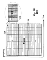
- Figure 1B shows the basic structure of a 10 ms frame 200 according to an embodiment of the invention.
- the horizontal axis indicates time and the vertical axis indicates frequency.
- the frame includes ten 1 ms sub-frames 210 in the time domain.
- the frame is also partitioned into frequency bands 220, e.g. fifty. The number of bands depends on the total bandwidth of the channels, which can be in the ranges of several megaHertz.
- Each sub-frame/band constitutes a resource block, see inset 230 and Figure 2C for details.
- FIG. 1C shows the basic method for antenna selection according to an embodiment of the invention.
- the base station 110 specifies times and frequencies to transmit sounding reference signals (SRSs) 161, and specifies which antennas of the set of available antennas to use to transmit the SRSs for the specified times and frequencies.
- the transceiver 101 transmits the SRSs 161 according to the specified times, frequencies, and antennas 151.
- the base station selects 170 a subset of antennas 181 based on the received SRSs 161.
- the base station indicates 180 the selected subset of antenna 181 to the transceiver.
- the transceiver 101 can transmit 190 data 191 using the selected subset of antennas 181.
- the transceiver can also use the same subset of antennas for receiving data from the base station.
- FIG. 2A shows a general structure of a sub-frame according to an embodiment of the invention.
- the transmission time of a frame is partitioned into TTIs (transmission time interval) 201 of duration 1.0 ms.
- TTIs transmission time interval
- the terms 'TTI' and 'sub-frame' are used interchangeably.
- the frame is 10 ms long, which includes 10 TTIs.
- the TTIs include time-slots 202.
- FIG. 2B shows a general structure of a time-slot according to an embodiment of the invention.
- the TTI is the basic transmission unit.
- One TTI includes two equal length time-slots 202 each with a duration of 0.5 ms.
- the time-slot includes seven long blocks (LB) 203 for symbols.
- the LBs are separated by cyclic prefixes (CP) 204.
- CP cyclic prefixes
- one TTI comprises fourteen LB symbols. It should be noted that the invention is not limited to a specific frame, sub-frame, or time-slot structure.
- FIG. 2C shows the details of one resource block (RB) 230 during one TTI 201 according to an embodiment of the invention.
- the TTI is partitioned, in time, into fourteen LBs 203. Each LB can carry a symbol.
- the entire system bandwidth e.g., of 5 MHz or 10 MHz or 20 MHz, is partitioned or divided into sub-carriers 205 at different frequencies. Groups of twelve contiguous sub-carriers, as shown, within one TTI are called resource blocks (RBs). For example, 10 MHz of bandwidth within 1 TTI might include fifty RBs in the frequency domain.
- the two shaded LBs 210 i.e., the 4 th and the 11 th LBs, carry data demodulation (DM) reference signals (RS) that are known to the receiver.
- DM data demodulation
- RS data demodulation reference signals
- the DM RS enables the receiver to estimate the channel state of the RBs assigned to the transceiver and coherently demodulate the unknown data carried in the other LBs. That is, in the prior art, DM reference signals are only used for channel estimation prior to data demodulation. For clarity the CPs are not shown in Figure 2C . It should be noted that the invention is not limited to a specific number of LBs during the TTI or the location of the DM RSs in the TTI. According to one embodiment of the invention, the DM reference signal is also used for antenna selection.
- SRS Sounding Reference Signal
- the other LBs are used for transmitting control and data signals, as well as uplink sounding reference signals (SRS).
- SRS uplink sounding reference signals
- the first LB can carry the SRS.
- the SRS is usually a wideband or variable bandwidth signal.
- the SRS enables the base station to estimate the frequency response of the entire system bandwidth or a portion thereof. This information enables the base station to perform resource allocation such as uplink frequency-domain scheduling.
- the SRSs are also used for antenna selection.
- a frequency-hopping (FH) based SRS is a frequency-hopping (FH) based SRS.
- FH frequency-hopping
- a hopping SRS with a bandwidth smaller than the system bandwidth, is transmitted based on a pre-determined hopping pattern.
- the hopped SRSs over multiple transmissions, span a large portion of the system bandwidth or even the entire system bandwidth. With frequency hopping the probability that transceivers interfere with each other during sounding is decreased.
- the eNodeB can enable and disable SRS transmission by the UE transceiver. Moreover, when antenna selection is enabled, the eNodeB can specify the SRS parameters to the transceiver, including transmission bandwidth, starting or ending bandwidth position, transmission period, cyclic shift hopping sequence, transmission sub-frame, repetition factor for indicating the density of the pilot subcarriers in the SRS LB, duration of SRS transmission, symbol position of SRS within a sub-frame, and hopping SRS related parameters, among others. Furthermore, to support antenna selection by using SRS, the same SRS is used by all antennas. Thus, the eNodeB knows in advance, which antenna is sending the SRS.
- SRS antenna selection SRS
- R-SRS regular SRS
- our invention comprises three levels of messages, namely, Level-A registration signaling, Level-B slow signaling, and Level-C fast signaling, all or some of which can be used for antenna selection.
- Level-A registration signaling Level-B slow signaling
- Level-C fast signaling All or some of which can be used for antenna selection.
- Table 1A and Table 1B A summary of the possible signaling messages for enabling antenna selection is shown in Table 1A and Table 1B, where the two tables correspond to two slightly different signaling options: Option1 and Option2.
- Option1 The major difference between Option1 and Option2 is the "SRS start/stop" message.
- SRS start/stop is a Level-B message in Option1 and a Level-C message in Option2.
- Option1 we first describe Option1 in details. Then, we describe Option2 by mainly focusing on the differences between the two options.
- the Level-A registration signaling indicates whether both the transceiver and the eNodeB support uplink (UL) antenna selection. If the eNodeB does not support antenna selection but the transceiver does, the transceiver can use open-loop antenna selection, which does not require any support from the eNodeB. This information is exchanged between the transceiver and the eNodeB at the beginning of the communications, for example, when the transceiver registers with the wireless network upon entry.
- UL uplink
- Level-B is a layer 3 (or radio resource control (RRC) layer) signaling that is used to set up AS training parameters for the SRS.
- Level-B is a slow form of signaling that is used infrequently.
- the eNodeB uses Level-B signaling to stop and start the transceiver to send the A-SRS, or to change the A-SRS parameters.
- Level-C is fast signaling that is used by the eNodeB to communicate to the transceiver its antenna selection decisions, and to enable the antenna selection to track short-term variations due to channel fading.
- the uplink In the uplink (UL), only the Level-A message is needed from the transceiver to notify the eNodeB of its capability of supporting AS. In the downlink (DL), some or all of the three levels of messages may be necessary.
- the Level-A registration signaling is used to indicate if both the transceiver and the eNodeB support uplink antenna selection. This information is exchanged between the transceiver and the eNodeB when the transceiver enters the network and before beginning data communications.
- the basic procedure between transceiver and eNodeB to exchange the registration information is shown in Figure 3 .
- the uplink (UL) 1-bit information is required for the UE transceiver 301 to notify the base station eNodeB 302 whether it is an antenna selection capable transceiver, or not.
- the downlink (DL) 1-bit information is needed for the eNodeB 302 to inform the transceiver about its capability to support uplink transmit AS.
- the "UE capability information” contains a “radio access capability” field.
- the “radio access capability” field further comprises a “physical channel capability” field. Similar to the “UE MIMO support” already included in the “physical channel capability", a 1-bit “UE AS support” field is added into the "physical channel capability” to indicate the UE's antenna selection capability.
- Level-A signaling information can be included into other messages.
- RRC radio resource control
- Level-B message [Option1] is shown in Table 2.
- the Level-B signaling is used to set up AS parameters. This information is required when the eNodeB requests the transceiver to start or stop sending the SRS, or to change A-SRS parameters.
- R-SRS and A-SRS share the same Level-B signaling message, except that two fields (i.e., "A-SRS Enable” and "Period2" shown in boldface in Table 2) are for A-SRS.
- A-SRS Enable i.e., "A-SRS Enable” and "Period2" shown in boldface in Table 2
- Period2 shown in boldface in Table 2
- Table 2 Frame structure for Level-B message [Option1] Field Size (bits) Comment SRS Start/Stop [1] Request to start (when set to 1) or stop (when set to 0) sending SRS.
- Periodic/Adaptive [1] Indicates whether the SRS is performed periodically (when set to 1, until told to stop) or adaptively (when set to 0, one-shot SRS).
- BW & Position The bandwidth (in terms of number of RBs) and the starting position (in terms of RB index) for the SRS.
- Start Sub-frame The index of the sub-frame within a radio frame that the UE starts sending the SRS.
- Symbol Position The index of the LB within a sub-frame at which the SRS is located (SRS is not necessary at the 1 st LB of a sub-frame).
- Period1 The interval (in terms of number of TTIs) between two consecutive SRSs. This value does not matter for non-hopping adaptive R-SRS.
- Period2 [FFS] The interval (in terms of number of SRSs) between two consecutive A-SRSs and pattern of transmission.
- Hopping Related Fields Indicates hopping related information such as number of hops, hopping pattern, etc.
- SRS Start/Stop when set to 1, indicates the request from the eNodeB to start sending SRS (for both A-SRS and R-SRS cases). Otherwise, when this bit is set to 0, then the eNodeB requests the transceiver to stop sending SRS.
- A-SRS Enable when set to 1, indicates that the A-SRS is enabled. Then, all the other fields of this message are used for setting up A-SRS parameters. The meaning of each field is described in the "Comment” column of Table 2. If “A-SRS Enable” is set to 0, then R-SRS is enabled. Thus, the other fields (except “Period2") of this message are used for setting up R-SRS parameters. By sharing parameter fields with R-SRS, the overhead for enabling A-SRS is low.
- Period1 indicates the interval (in terms of number of TTIs) between any two consecutive SRSs, which is used for both A-SRS and R-SRS.
- Period2 indicates the interval between two consecutive A-SRSs as well as the pattern of transmission of the A-SRS.
- Period2 the eNodeB can dynamically adjust the portion of the SRSs that are sent from the unselected antenna, achieving a tradeoff between the performance and the antenna-switching overhead.
- the format e.g., either A-SRS or R-SRS; either periodic or adaptive, etc
- Level-B message A number of variations for the structure of the above Level-B message are possible. First, all the fields need not be sent together at the same time. Depending on the function categories, the Level-B message might be split into sub-messages and sent separately. Second, the 1-bit field "A-SRS Enable" can be inside another field of this message. Depending on how R-SRS signaling is designed in 3GPP LTE, A-SRS signaling may need to be adjusted accordingly in compliance with R-SRS.
- the frame structure for Level-C message [Option1] is shown in Table 3.
- the Level-C fast signaling message is used to signal the transceiver about which antenna to use for data transmission. For selecting one antenna out of two possible candidates, a 1-bit information field suffices. One option is to include this 1-bit information in the "uplink scheduling grant" message. It should be noted that all the message format descriptions provided herein are only examples.
- the "uplink scheduling grant” is used by the eNodeB to make an uplink scheduling decision for a transceiver specified by the "ID" field.
- the eNodeB In the “resource assignment” field, the eNodeB notifies the transceiver which RBs are assigned for its data transmission.
- the 1-bit antenna selection decision can be created in this field. Thus, when antenna selection is enabled, the "resource assignment" field indicates a joint scheduling and antenna selection decision.
- the "AS Decision" bit when set to 1, indicates that the transceiver should switch to a different transmit antenna to transmit data. If this field is set to 0, then the transceiver uses the same antenna to transmit data. Upon receiving this message, the transceiver continues to use the same antenna, or switches to a different antenna, according to the decision made by the eNodeB.
- the above method corresponds to a "relative antenna index" based approach. That is, the eNodeB does not know exactly which antenna is used. Instead, the eNodeB just notifies the transceiver to either "switch” or “not switch” the subset of selected antennas. It is also possible to use an "absolute antenna index" based approach to indicate the antenna selection decision, where the eNodeB notifies the transceiver either to use the 1 st antenna or the 2 nd antenna, or otherwise designated subsets.
- AS decision information in other fields (e.g., "TF" field) of the uplink scheduling grant message, or even inside other message.
- [Option2] is similar to [Option1] except for the "SRS start/stop" message, which is a Level-B message in [Option1] and a Level-C message in [Option2].
- the advantage of [Option 2] is that the SRSs (both R-SRS and A-SRS) can be configured quickly to start/stop (especially stop) for granting a priority to other transceivers.
- the disadvantage is the slightly larger payload of the Level C messages.
- the A-SRS parameters are combined together with SRS request (either to start or stop).
- the A-SRS parameters and SRS request are sent separately. Therefore, in [Option2], the Level-B message does not include "SRS start/stop" field (i.e., the first field in Table 2). Meanwhile, 2 bits are added to the Level-C message in order to achieve the same "SRS start/stop" function. Thus, a total of 3 bits are required for Level-C message in [Option2].
- Level-C message [Option2] are shown in Table 4.
- the Level-C message is used to indicate A-SRS request to start or stop and antenna selection decision.
- the transceiver also checks the "AS Decision" bit.
- the responses to "AS Decision” bit are the same as [Option1] at transceiver.
- SRS Start and SRS Stop information inside another field (e.g., "TF" field) of the uplink scheduling grant message, or even inside other message.
- the "SRS Start” and “SRS Stop” can be at a separate message from the "AS Decision”.
- the "SRS Start” and “SRS Stop” can be combined together into 1 bit, just as that in [Option1].
- A-SRS and R-SRS share the same SRS request.
- A-SRS signaling may need to be adjusted accordingly in compliance with R-SRS.
- our protocol utilizes the sounding reference signal (SRS) 161 for uplink transmit antenna selection, R1-073067, "Adaptive antenna switching with low sounding reference signal overhead," Mitsubishi Electric, 3GPP RAN1#49bis, R1-073068, “Impact of sounding reference signal loading on system-level performance of adaptive antenna switching,” Mitsubishi Electric, 3GPP RAN1#49bis.
- SRS sounding reference signal
- the antenna switching is performed within a TTI , but we do not preclude between TTI switching.
- the protocol is flexible and applicable to different antenna selection scenarios.
- both periodic antenna selection and adaptive antenna selection are supported.
- the protocol can switch between different periodic AS (with different sounding intervals), or between different adaptive AS (with different sounding intervals), or between periodic and adaptive AS, or even allow them together, as dictated by the eNodeB.
- the protocol supports antenna selection based on different SRSs, including wideband SRS, variable bandwidth SRS, and narrow-band SRS.
- the protocol supports antenna selection for packet retransmission in both asynchronous HARQ and synchronous HARQ modes.
- the current protocol focuses on 1 out of 2 antenna selection, while the extension to multiple antenna selection is possible with a cost of additional signaling overhead.
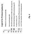
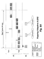
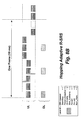
- Figure 4 shows the legend for protocol [Option1], which is used for the Figure 5A to Figure 8B , according to an embodiment of the invention.
- the legends are intended to simplify the details of the otherwise complex drawings.
- the legends are Wideband or variable bandwidth SRS 401, Narrow-band hopping SRS 402, Data block (sub-frame) if no SRS is sent at the same TTI 403, Data block (sub-frame) if SRS is sent at the same TTI 404, No data to send in a TTI 405, Level-B slower signaling: SRS parameters & SRS request 406, and Level-C faster signaling: AS & scheduling decision 407.
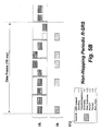
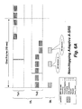
- FIGs 5A and 5B show the protocol illustration for non-hopping periodic A-SRS and R-SRS, respectively.
- the eNodeB sends a set of SRS parameters 501, which includes an "SRS Start" request.
- the detailed parameters are listed at the bottom-left corner 502 in Figure 5A .
- the transceiver receives this request at the 2 nd TTI 503, and gets ready to send SRS as per the parameters.
- the difference is that the decision from eNodeB is only a scheduling decision, not an antenna switching decision.
- the "Period2" field is no use for R-SRS case.
- FIGs 6A and 6B show the protocol for non-hopping adaptive A-SRS and R-SRS, respectively.
- adaptive SRS is a "one-shot" SRS transmission as per the eNodeB's request.
- A-SRS shown in Figure 6A two SRSs are sent by the two antennas successively, with the interval determined by the "Period1" field in the parameter list.
- the eNodeB makes scheduling and/or AS decision based on the received A-SRSs.
- the R-SRS shown in Figure 6B only one SRS is sent by the transmit antenna. Therefore, the "Period1" field is of no use in this case.
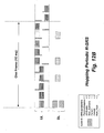
- FIGs 7A and 7B show the protocol for hopping periodic A-SRS and R-SRS, respectively.
- Num_Hops 2 hops
- each narrow-band SRS spans half of the available bandwidth.
- the SRS 702 at the 5 th TTI, the SRS 703 at the 8 th TTI, and the SRS 704 at the 1 st TTI of the next fame are sent from the unselected antenna, while the rest SRSs are sent from the selected antenna.
- the eNodeB can make a scheduling and AS decision each time when it receives an A-SRS.
- the transceiver transmits R-SRS from only one antenna.
- a total of 2 SRSs are required in each cycle to sound the entire bandwidth.
- the eNodeB makes scheduling decisions without any antenna selection.
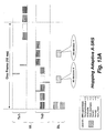
- Figure 8A and 8B show the protocol for hopping adaptive A-SRS and R-SRS, respectively.
- the transceiver upon receiving the request 801 from the eNodeB, the transceiver sends a total of 4 SRSs. Based on one or more SRSs, the eNodeB can make AS and scheduling decisions at any time.
- AS Enable 0
- a total of 2 SRSs is sent by the transceiver for the eNodeB to make scheduling decisions.
- the interval between the 2 SRSs is determined by the "Period1" field.
- Figure 9 shows the legend for protocol [Option2], which is used for the illustrations from Figure 10A to Figure 13B .
- the legends are Wideband or variable bandwidth SRS 901, Narrow-band hopping SRS 902, Data block (sub-frame) if no SRS is sent at the same TTI 903, Data block (sub-frame) if SRS is sent at the same TTI 904, No data to send in a TTI 905, Level-B slower signaling: SRS parameters, 906, Level-C faster signaling: SRS request (to start) 907, and Level-C faster signaling: AS & scheduling decision 908. For clarity Level-A signaling exchange is omitted herein. It should be noted that all the protocol illustrations provided herein are only
- Figures 10A to 13B show the same SRS scenarios when the signaling is set to [Option2], respectively.
- the Level-B SRS parameters are sent separately from the Level-C SRS start/stop request.
- the transceiver has obtained the required SRS parameters in a separate Level-B message (or uses default values for the parameter values it has not received yet).
- the eNodeB can send the SRS parameters 1001 and the SRS request 1002 at the same TTI.
- the SRS parameter 1101 can also be sent before the SRS request 1102. The other procedures are the same as [Option1].
- a Level-B slower signaling from the eNodeB to the transceiver is required for both [Option1] and [Option2] to set up different SRS parameters.
- an "SRS Start" from the eNodeB to the transceiver is also needed.
- the eNodeB can possibly send SRS request and the AS decision in the same TTI. It should also be noted that when the number of hops (i.e., the "Num_Hops" field in parameter list) is larger than 2, different hopping patterns that jointly span the frequency-space domain can be designed. The pattern can be either signaled by the eNodeB or is chosen from a pre-determined set. In Figures 5A to 8B and Figures 10A to 13B , only the procedure of "SRS Start” is shown. The procedure of "SRS Stop” is not shown in these figures, and is sent in a similar manner.
- the eNodeB indicates to the transceiver when, which RBs, and with what MCS (modulation and coding scheme) to retransmit the packet. Because the eNodeB has complete control over the packet retransmission in asynchronous HARQ, the eNodeB can also signal the transceiver whether or not to switch the antenna for retransmission. It can also indicate to the transceiver to send an aperiodic or a periodic A-SRS. In this case, the eNodeB makes a j oint AS and scheduling decision for the retransmitted packet, similar to that for a normal packet.
- MCS modulation and coding scheme
- the transceiver knows a priori exactly when to retransmit the packet when it does not receive an ACK from the eNodeB after a pre-specified number of TTIs. In this case, the transceiver uses the same resource block (RB) and same MCS for the retransmission. Because the transceiver has complete control over the packet retransmission in synchronous HARQ, whenever retransmission occurs, the transceiver can automatically switch to another subset of antennas to retransmit (using the same RB and MCS). This is to avoid the scenario that the channel quality of the previously selected subset of antennas is poor.
- RB resource block
- the transceiver Upon receiving the Level-B message, the transceiver first checks the "Period1" field. If “Period1" is non-zero, then the transceiver starts sending SRS according to the indicated format, e.g., either A-SRS or R-SRS, either periodic or adaptive, etc. as defined in the parameter list of the Level-B message. Otherwise, when the Period1 field is zero, the transceiver stops sending SRS, and the other fields of this message are omitted.
- the indicated format e.g., either A-SRS or R-SRS, either periodic or adaptive, etc.
- Level-B signaling message is possible.
- the fields are partitioned into sub-messages and transmitted separately.
- Some parameters such as "Symbol Position” and “BW & Position” can be specific for a particular cell or base station. Therefore, it is also possible to broadcast the parameters via the dynamic broadcast channel (D-BCH) by the eNodeB (base station).
- D-BCH dynamic broadcast channel
- the AS dependent parameters "A-SRS Enable” and “Period2" can be an "OP" field in L3 signaling, meaning an optional extension. If the "Period2" parameter is ignored, then the SRSs are alternately transmitted from the two transmit antennas in the A-SRS case.
- the sub-frame position of UL grant is used to implicitly indicate antenna selection decisions. Specifically, even sub-frames of the UL grants indicate using the first antenna or subset of antennas, and odd sub-frames indicate the second antenna or subset of antennas.
- the UL grant when transmitted during the even sub-frame, indicates that the transceiver will use the first antenna to send data. On the other hand, if the UL grant is transmitted during the odd sub-frame, then the UE will use the second antenna to send data.
- the above method corresponds to an "absolute antenna index” based approach. It is also possible to use a “relative antenna index” based approach, where the even and odd sub-frames of the UL grant indicate "switch to a different antenna” and "keep using the same antenna", respectively.
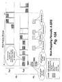
- Figure 14A shows the protocol for non-hopping periodic A-SRS in the presence of parameter "Period2".
- the eNodeB sends Level-B signaling including a set of SRS parameters 1401, which is treated as an implicit "SRS Start" request. Only relevant parameters are shown in the list 1401, and the other parameters are omitted for simplicity.
- the eNodeB Based on the received SRS 1403, the eNodeB makes a joint scheduling and AS decision 1404 in the 3 rd sub-frame. Because the UL grant 1404 is transmitted at the odd sub-frame 1421, this control signaling indicates that the UE should use Tx2 for data transmission.
- the transceiver receives the decision in the 4 th TTI 1405, and responds accordingly.
- the UL grants transmitted at the 5 th TTI of the same frame and the 1 st TTI of the next frame also indicates that the UE should use Tx2 for data transmission.
- the UL grants transmitted at the even (6 th , 8 th , and 10 th ) TTIs indicates 1422 that the UE should switch to Tx1 for data transmission.
- this message requests the UE to stop sending SRS.
- the UE disables SRS 1410 at the 4 th TTI of the next frame.
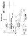
- Figure 14B shows the protocol for non-hopping periodic A-SRS, when ignoring the parameter "Period2".
- the only difference between Figure 14A and Figure 14B is that, in the absence of "Period2", the SRSs 1444 are alternately transmitted by the two antennas.
- the transmission pattern of SRS is independent of data transmission.
- protocol illustration Figure 14A and 14B we only show the examples of non-hopping A-SRS.
- the protocol also supports other SRS patterns such as narrow-band hopping SRS, adaptive SRS, R-SRS, and the combination of the above as described herein.
- the embodiments of the invention provide signaling and protocol for antenna selection in the uplink of OFDM 3GPP wireless network between the transceiver and the eNodeB.
Landscapes
- Engineering & Computer Science (AREA)
- Computer Networks & Wireless Communication (AREA)
- Signal Processing (AREA)
- Mobile Radio Communication Systems (AREA)
- Radio Transmission System (AREA)
Applications Claiming Priority (2)
| Application Number | Priority Date | Filing Date | Title |
|---|---|---|---|
| US11/834,345 US8086272B2 (en) | 2007-08-06 | 2007-08-06 | Wireless networks incorporating antenna selection based on received sounding reference signals |
| US11/924,703 US8055301B2 (en) | 2007-08-06 | 2007-10-26 | Wireless networks incorporating implicit antenna selection based on received sounding reference signals |
Publications (2)
| Publication Number | Publication Date |
|---|---|
| EP2023503A2 true EP2023503A2 (fr) | 2009-02-11 |
| EP2023503A3 EP2023503A3 (fr) | 2011-11-16 |
Family
ID=40085581
Family Applications (1)
| Application Number | Title | Priority Date | Filing Date |
|---|---|---|---|
| EP08013623A Withdrawn EP2023503A3 (fr) | 2007-08-06 | 2008-07-29 | Procédé de sélection d'antennes dans un réseau sans fil |
Country Status (3)
| Country | Link |
|---|---|
| US (1) | US8055301B2 (fr) |
| EP (1) | EP2023503A3 (fr) |
| JP (1) | JP2009060596A (fr) |
Cited By (6)
| Publication number | Priority date | Publication date | Assignee | Title |
|---|---|---|---|---|
| WO2011090413A1 (fr) * | 2010-01-21 | 2011-07-28 | Telefonaktiebolaget L M Ericsson (Publ) | Transmission srs en poussée |
| EP2592803A4 (fr) * | 2010-08-09 | 2013-08-07 | Huawei Tech Co Ltd | Procédé, station de base et équipement d'abonné pour envoyer et recevoir un signal de référence de sondage |
| CN104363630A (zh) * | 2010-10-04 | 2015-02-18 | 株式会社Ntt都科摩 | 移动终端装置、无线通信方法以及无线通信系统 |
| AU2014265044B2 (en) * | 2010-10-04 | 2016-05-19 | Ntt Docomo, Inc. | Radio base station apparatus, mobile terminal apparatus and radio communication method |
| CN110233718A (zh) * | 2013-12-27 | 2019-09-13 | 华为技术有限公司 | 自适应tti与lte共存的系统和方法 |
| CN111480309A (zh) * | 2017-10-11 | 2020-07-31 | Lg电子株式会社 | 发送和接收srs的方法及其通信设备 |
Families Citing this family (59)
| Publication number | Priority date | Publication date | Assignee | Title |
|---|---|---|---|---|
| JP3728631B2 (ja) * | 1995-07-15 | 2005-12-21 | 森田産業株式会社 | レンタルマット敷設方法 |
| US8824420B2 (en) * | 2007-03-22 | 2014-09-02 | Mitsubishi Electric Research Laboratories, Inc. | Method and system for generating antenna selection signals in OFDM tranceivers with fewer RF chains than antennas in MIMO wireless networks |
| CN104468067B (zh) | 2007-08-08 | 2017-11-24 | 知识产权之桥一号有限责任公司 | 基站装置和接收方法 |
| ES2964018T3 (es) | 2007-08-08 | 2024-04-03 | Ericsson Telefon Ab L M | Sondeo de canales utilizando múltiples configuraciones de señales de sondeo |
| CN103402264B (zh) | 2007-08-14 | 2017-06-06 | 松下电器产业株式会社 | 基站装置、集成电路和通信方法 |
| WO2009085973A2 (fr) * | 2007-12-21 | 2009-07-09 | Research In Motion Limited | Système et procédé pour utilisation de ressource en liaison ascendante |
| US9332264B2 (en) * | 2007-12-30 | 2016-05-03 | Intel Corporation | Configurable performance motion estimation for video encoding |
| CN101505485B (zh) * | 2008-02-05 | 2014-11-05 | 三星电子株式会社 | Lte tdd系统中发送srs的方法和装置 |
| US7965657B2 (en) * | 2008-03-26 | 2011-06-21 | Texas Instruments Incorporated | Sounding reference signal cell specific sub-frame configuration |
| US9363054B2 (en) * | 2008-04-29 | 2016-06-07 | Texas Instruments Incorporated | Sounding reference signal user equipment specific sub-frame configuration |
| US9025471B2 (en) | 2008-05-07 | 2015-05-05 | Mitsubishi Electric Research Laboratories, Inc. | Antenna selection with frequency-hopped sounding reference signals |
| US8238405B2 (en) * | 2009-03-31 | 2012-08-07 | Mitsubishi Electric Research Laboratories, Inc. | Antenna selection with frequency-hopped sounding reference signals |
| EP2297980B1 (fr) * | 2008-06-24 | 2018-08-29 | Mitsubishi Electric Corporation | Sélection d antennes à l aide de signaux de référence de sondage avec saut de fréquence |
| CN101615928B (zh) * | 2008-06-25 | 2016-05-18 | 三星电子株式会社 | Lte系统中传输srs信令的方法和装置 |
| US8724488B2 (en) * | 2009-03-17 | 2014-05-13 | Interdigital Patent Holdings, Inc. | Method and apparatus for power control of sounding reference signal (SRS) transmission |
| EP2765811B1 (fr) * | 2009-03-17 | 2017-08-16 | Huawei Technologies Co., Ltd. | Procédé, dispositif, terminal et produit logiciel d'ordinateur pour déterminer un mode de transmission |
| KR101709499B1 (ko) * | 2009-03-25 | 2017-02-23 | 엘지전자 주식회사 | 무선 통신 시스템에서 사운딩 참조 신호 송신 방법 및 이를 위한 장치 |
| JP5378848B2 (ja) * | 2009-03-26 | 2013-12-25 | 京セラ株式会社 | 無線基地局、無線基地局におけるサウンディング制御方法、および無線基地局におけるサウンディング制御プログラム |
| KR101128817B1 (ko) * | 2009-05-15 | 2012-03-23 | 엘지전자 주식회사 | 무선 통신 시스템에서 사운딩 참조 신호 송신 방법 및 이를 위한 장치 |
| US8855062B2 (en) | 2009-05-28 | 2014-10-07 | Qualcomm Incorporated | Dynamic selection of subframe formats in a wireless network |
| US9137815B2 (en) * | 2009-06-17 | 2015-09-15 | Qualcomm Incorporated | Multi-user multiple input multiple output wireless communications |
| CN101594633B (zh) * | 2009-06-19 | 2015-06-10 | 中兴通讯股份有限公司 | 使用多天线传输测量参考信号的基站、终端、系统和方法 |
| US8649337B2 (en) * | 2009-06-19 | 2014-02-11 | Qualcomm Incorporated | Control channel design for dynamic sub-frame selection |
| WO2011013410A1 (fr) * | 2009-07-29 | 2011-02-03 | 日本電気株式会社 | Système de communication sans fil à sauts multiples, dispositif de commande, station relais et procédé de commande |
| US9602250B2 (en) * | 2009-08-18 | 2017-03-21 | Lg Electronics Inc. | Method for retransmitting data in wireless communication system |
| JP5415197B2 (ja) * | 2009-09-24 | 2014-02-12 | シャープ株式会社 | 無線通信システム、基地局装置および移動局装置 |
| JP5471343B2 (ja) * | 2009-11-18 | 2014-04-16 | 富士通株式会社 | 基地局および品質測定方法 |
| US9531514B2 (en) * | 2009-12-03 | 2016-12-27 | Qualcomm Incorporated | Sounding reference signal enhancements for wireless communication |
| US20110171964A1 (en) * | 2010-01-08 | 2011-07-14 | Mediatek Inc. | Resource allocation and signaling method for LTE sounding |
| JP2013516816A (ja) * | 2010-01-08 | 2013-05-13 | 聯發科技股▲ふん▼有限公司 | Lteサウンディングのリソース割り当てとシグナル伝達 |
| JP2013516817A (ja) * | 2010-01-08 | 2013-05-13 | 聯發科技股▲ふん▼有限公司 | 無線通信システムにおけるアップリンクチャネルサウンディングのマルチアンテナリソース割り当て方法 |
| EP2536047B1 (fr) | 2010-02-09 | 2020-03-04 | LG Electronics Inc. | Procédé d'émission d'un signal montant dans un système de communication sans fil et dispositif correspondant |
| EP2360864A1 (fr) * | 2010-02-12 | 2011-08-24 | Panasonic Corporation | (Dés)activation de véhicules de composants dans les systèmes de communication utilisant une agrégation de porteuses |
| JP2011166699A (ja) * | 2010-02-15 | 2011-08-25 | Ntt Docomo Inc | 無線基地局装置、移動端末装置及び無線通信方法 |
| KR101643225B1 (ko) * | 2010-02-23 | 2016-07-27 | 엘지전자 주식회사 | 무선 통신 시스템에서 사운딩 신호 송신 방법 |
| CA2797249A1 (fr) * | 2010-04-29 | 2011-11-03 | Fujitsu Limited | Procede et appareil d'emission aperiodique de signaux de reference de sondage |
| KR101752025B1 (ko) * | 2010-04-30 | 2017-06-28 | 선 페이턴트 트러스트 | 단말 장치 및 참조 신호의 전력 제어 방법 |
| US8780860B2 (en) * | 2010-05-01 | 2014-07-15 | Pantech Co., Ltd. | Apparatus and method for transmitting sounding reference signal in wireless communication system supporting multiple component carriers |
| JP5530257B2 (ja) * | 2010-05-27 | 2014-06-25 | 京セラ株式会社 | 基地局、基地局の通信方法、移動局、移動局の通信方法 |
| KR20110137983A (ko) * | 2010-06-18 | 2011-12-26 | 주식회사 팬택 | 다중 요소 반송파 시스템에서 잉여전력 정보의 전송장치 및 방법 |
| KR101227520B1 (ko) | 2010-07-09 | 2013-01-31 | 엘지전자 주식회사 | 다중 안테나 무선 통신 시스템에서 상향링크 참조 신호 송신 방법 및 이를 위한 장치 |
| WO2012026603A1 (fr) * | 2010-08-27 | 2012-03-01 | 京セラ株式会社 | Station de base sans fil et procédé de commande de communication |
| JP5654602B2 (ja) * | 2010-08-27 | 2015-01-14 | 京セラ株式会社 | 無線基地局及び通信制御方法 |
| WO2012026601A1 (fr) * | 2010-08-27 | 2012-03-01 | 京セラ株式会社 | Station de base sans fil et procédé de commande de communication |
| AU2010361416A1 (en) * | 2010-10-01 | 2013-05-02 | Blackberry Limited | Frequency-hopping method for LTE aperiodic sounding reference signals |
| EP3621390B1 (fr) * | 2010-11-16 | 2024-10-09 | Sun Patent Trust | Dispositif de communication et procédé de commande de transmission srs |
| JP2012129962A (ja) * | 2010-12-17 | 2012-07-05 | Kyocera Corp | 無線基地局、無線端末及び通信制御方法 |
| JP5629607B2 (ja) * | 2011-02-25 | 2014-11-26 | 京セラ株式会社 | 無線基地局及び通信制御方法 |
| JP5775706B2 (ja) * | 2011-02-25 | 2015-09-09 | 京セラ株式会社 | 無線基地局及び通信制御方法 |
| US20130329687A1 (en) * | 2011-02-25 | 2013-12-12 | Kyocera Corporation | Radio base station and communication control method |
| JP5632319B2 (ja) | 2011-03-29 | 2014-11-26 | 京セラ株式会社 | 基地局 |
| US9337982B2 (en) * | 2013-04-05 | 2016-05-10 | Qualcomm Incorporated | Adaptive antenna management in LTE |
| JP5550774B2 (ja) * | 2013-09-24 | 2014-07-16 | 京セラ株式会社 | 無線端末、サウンディング情報送信方法、およびサウンディング情報送信プログラム |
| EP3361804B1 (fr) * | 2016-02-04 | 2021-05-19 | Guangdong Oppo Mobile Telecommunications Corp., Ltd. | Procédé et dispositif de transmission d'informations de liaison montante sur une porteuse sans licence |
| JP6891419B2 (ja) | 2016-07-29 | 2021-06-18 | ソニーグループ株式会社 | 端末装置、基地局、方法及び記録媒体 |
| EP3625996B1 (fr) | 2017-05-18 | 2021-07-07 | Telefonaktiebolaget LM Ericsson (publ) | Transmission de signal de référence de sondage écoénergétique |
| WO2019110869A1 (fr) * | 2017-12-04 | 2019-06-13 | Nokia Technologies Oy | Surveillance de liens avec auto-raccordement pour réseaux sans fil |
| CN110149132B (zh) * | 2019-07-08 | 2021-07-20 | 维沃移动通信有限公司 | 一种发射天线的切换方法及终端设备 |
| CN115603786B (zh) * | 2021-07-09 | 2025-03-14 | 华为技术有限公司 | 信号发射方法及无线通信装置 |
Family Cites Families (6)
| Publication number | Priority date | Publication date | Assignee | Title |
|---|---|---|---|---|
| GB0212165D0 (en) * | 2002-05-27 | 2002-07-03 | Nokia Corp | A wireless system |
| US7120395B2 (en) * | 2003-10-20 | 2006-10-10 | Nortel Networks Limited | MIMO communications |
| US7853205B2 (en) * | 2005-11-02 | 2010-12-14 | Texas Instruments Incorporated | Methods for improving transmission efficiency of control channels in communication systems |
| US7620423B2 (en) * | 2005-12-07 | 2009-11-17 | Cisco Technology, Inc. | Method and system for creating beamformed channels in a multi-input multi-output network |
| US8417248B2 (en) * | 2006-08-14 | 2013-04-09 | Texas Instruments Incorporated | Methods and apparatus to schedule uplink transmissions in wireless communication systems |
| KR101380558B1 (ko) * | 2007-06-19 | 2014-04-02 | 엘지전자 주식회사 | 사운딩 기준신호의 전송방법 |
-
2007
- 2007-10-26 US US11/924,703 patent/US8055301B2/en not_active Expired - Fee Related
-
2008
- 2008-07-25 JP JP2008191866A patent/JP2009060596A/ja active Pending
- 2008-07-29 EP EP08013623A patent/EP2023503A3/fr not_active Withdrawn
Non-Patent Citations (6)
| Title |
|---|
| MITSUBISHI ELECTRIC ET AL: "Low cost training for transmit antenna selection on the uplink", 3GPP DRAFT; R1-063089, 3RD GENERATION PARTNERSHIP PROJECT (3GPP), vol. RAN WG1, no. Riga, Latvia; 20061101, 1 November 2006 (2006-11-01), XP050103548, * |
| NOKIA SIEMENS NETWORKS ET AL: "UL Sounding Reference Signal", 3GPP DRAFT; R1-072988, 3RD GENERATION PARTNERSHIP PROJECT (3GPP), vol. RAN WG1, no. Orlando, USA; 20070620, 20 June 2007 (2007-06-20), XP050106652, * |
| NOKIA SIEMENS NETWORKS ET AL: "UL sounding", 3GPP DRAFT; R1-072296, 3RD GENERATION PARTNERSHIP PROJECT (3GPP), vol. RAN WG1, no. Kobe, Japan; 20070502, 2 May 2007 (2007-05-02), XP050106026, * |
| NORTEL: "Adaptation between Closed-loop and Open-loop Switching Transmit Diversities for UL MIMO", 3GPP DRAFT; R1-070712(NORTEL-UL_ANTENNACL_SWITCHING), 3RD GENERATION PARTNERSHIP PROJECT (3GPP), vol. RAN WG1, no. St. Louis, USA; 20070206, 6 February 2007 (2007-02-06), XP050104744, * |
| NTT DOCOMO ET AL: "Closed Loop Antenna Switching in E-UTRA Uplink", 3GPP DRAFT; R1-070860 CL-BASED ANTENNA SWITCHING, 3RD GENERATION PARTNERSHIP PROJECT (3GPP), vol. RAN WG1, no. St. Louis, USA; 20070206, 6 February 2007 (2007-02-06), XP050104875, * |
| Samsung: "Summary of Reflector Discussions on EUTRA UL RS", 3GPP TSG RAN WG1 Meeting #49bis, 25 June 2007 (2007-06-25), pages 1-4, XP002660335, Orlando, FL, USA Retrieved from the Internet: URL:http://www.3gpp.org/ftp/Specs/html-info/TDocExMtg--R1-49b--26481.htm * |
Cited By (18)
| Publication number | Priority date | Publication date | Assignee | Title |
|---|---|---|---|---|
| WO2011090413A1 (fr) * | 2010-01-21 | 2011-07-28 | Telefonaktiebolaget L M Ericsson (Publ) | Transmission srs en poussée |
| US10097324B2 (en) | 2010-01-21 | 2018-10-09 | Telefonaktiebolaget Lm Ericsson (Publ) | SRS transmission in PUSCH |
| EP2592803A4 (fr) * | 2010-08-09 | 2013-08-07 | Huawei Tech Co Ltd | Procédé, station de base et équipement d'abonné pour envoyer et recevoir un signal de référence de sondage |
| US9681443B2 (en) | 2010-10-04 | 2017-06-13 | Ntt Docomo, Inc. | Radio base station apparatus, mobile terminal apparatus and radio communication method |
| RU2654500C2 (ru) * | 2010-10-04 | 2018-05-21 | Нтт Докомо, Инк. | Мобильный терминал, способ радиосвязи и система радиосвязи |
| AU2011313367B2 (en) * | 2010-10-04 | 2015-11-26 | Ntt Docomo, Inc. | Radio base station apparatus, mobile terminal apparatus and radio communication method |
| AU2014265044B2 (en) * | 2010-10-04 | 2016-05-19 | Ntt Docomo, Inc. | Radio base station apparatus, mobile terminal apparatus and radio communication method |
| US9629149B2 (en) | 2010-10-04 | 2017-04-18 | Ntt Docomo, Inc. | Radio base station apparatus, mobile terminal apparatus and radio communication method |
| EP2627145A4 (fr) * | 2010-10-04 | 2015-05-06 | Ntt Docomo Inc | Appareil formant station de base radio, appareil formant terminal mobile et procédé de communication sans fil |
| US9832766B2 (en) | 2010-10-04 | 2017-11-28 | Ntt Docomo, Inc. | Radio base station apparatus, mobile terminal apparatus and radio communication method |
| EP2890038A1 (fr) * | 2010-10-04 | 2015-07-01 | Ntt Docomo, Inc. | Appareil de station de base radio, appareil terminal mobile et procédé de communication radio |
| CN104363630A (zh) * | 2010-10-04 | 2015-02-18 | 株式会社Ntt都科摩 | 移动终端装置、无线通信方法以及无线通信系统 |
| CN104363630B (zh) * | 2010-10-04 | 2019-01-01 | 株式会社Ntt都科摩 | 移动终端装置、无线通信方法以及无线通信系统 |
| CN110233718A (zh) * | 2013-12-27 | 2019-09-13 | 华为技术有限公司 | 自适应tti与lte共存的系统和方法 |
| US11606179B2 (en) | 2013-12-27 | 2023-03-14 | Huawei Technologies Co., Ltd. | System and method for adaptive TTI coexistence with LTE |
| CN111480309A (zh) * | 2017-10-11 | 2020-07-31 | Lg电子株式会社 | 发送和接收srs的方法及其通信设备 |
| CN111480309B (zh) * | 2017-10-11 | 2023-05-23 | Lg电子株式会社 | 发送和接收srs的方法及其通信设备 |
| US11700096B2 (en) | 2017-10-11 | 2023-07-11 | Lg Electronics Inc. | Method for transmitting and receiving SRS and communication device therefor |
Also Published As
| Publication number | Publication date |
|---|---|
| US8055301B2 (en) | 2011-11-08 |
| EP2023503A3 (fr) | 2011-11-16 |
| US20090042616A1 (en) | 2009-02-12 |
| JP2009060596A (ja) | 2009-03-19 |
Similar Documents
| Publication | Publication Date | Title |
|---|---|---|
| US8055301B2 (en) | Wireless networks incorporating implicit antenna selection based on received sounding reference signals | |
| US8086272B2 (en) | Wireless networks incorporating antenna selection based on received sounding reference signals | |
| US11979214B2 (en) | Transmission of information in a wireless communication system | |
| US8046029B2 (en) | Method for selecting antennas in a wireless networks | |
| US8331297B2 (en) | Method and system for generating antenna selection signals in wireless networks | |
| CN102017453B (zh) | 利用跳频探测参考信号的天线选择 | |
| US8223723B2 (en) | Method and system for generating antenna selection signals in wireless networks | |
| US8009580B2 (en) | Signaling and training for antenna selection in OFDMA networks | |
| CN102017455B (zh) | 利用跳频探测参考信号的天线选择 | |
| CN109845166B (zh) | 在无线通信系统中通过终端和基站发送和接收信号的方法和支持该方法的设备 | |
| US7583939B2 (en) | Method and system for antenna selection in wireless networks | |
| CN109478942B (zh) | 无线通信系统中发送和接收下行链路信号的方法及其装置 | |
| CN118784009A (zh) | 传输方法及装置 | |
| CN102017454B (zh) | 无线通信网络以及无线通信网络中的天线选择方法 | |
| US20110188593A1 (en) | Mobile station apparatus, mobile communication system and transmission method | |
| HK1172450B (en) | Transmission of information in a wireless communication system | |
| HK1170620B (en) | Transmission of information in a wireless communication system | |
| HK1172450A (en) | Transmission of information in a wireless communication system |
Legal Events
| Date | Code | Title | Description |
|---|---|---|---|
| PUAI | Public reference made under article 153(3) epc to a published international application that has entered the european phase |
Free format text: ORIGINAL CODE: 0009012 |
|
| AK | Designated contracting states |
Kind code of ref document: A2 Designated state(s): AT BE BG CH CY CZ DE DK EE ES FI FR GB GR HR HU IE IS IT LI LT LU LV MC MT NL NO PL PT RO SE SI SK TR |
|
| AX | Request for extension of the european patent |
Extension state: AL BA MK RS |
|
| PUAL | Search report despatched |
Free format text: ORIGINAL CODE: 0009013 |
|
| RIC1 | Information provided on ipc code assigned before grant |
Ipc: H04B 7/06 20060101AFI20111004BHEP |
|
| AK | Designated contracting states |
Kind code of ref document: A3 Designated state(s): AT BE BG CH CY CZ DE DK EE ES FI FR GB GR HR HU IE IS IT LI LT LU LV MC MT NL NO PL PT RO SE SI SK TR |
|
| AX | Request for extension of the european patent |
Extension state: AL BA MK RS |
|
| RIC1 | Information provided on ipc code assigned before grant |
Ipc: H04B 7/06 20060101AFI20111012BHEP |
|
| STAA | Information on the status of an ep patent application or granted ep patent |
Free format text: STATUS: THE APPLICATION IS DEEMED TO BE WITHDRAWN |
|
| AKY | No designation fees paid | ||
| REG | Reference to a national code |
Ref country code: DE Ref legal event code: R108 |
|
| 18D | Application deemed to be withdrawn |
Effective date: 20120201 |
|
| REG | Reference to a national code |
Ref country code: DE Ref legal event code: R108 Effective date: 20120725 |