EP2023630A2 - Système de conférence, serveur, procédé d'affichage d'images et produit de programme informatique - Google Patents
Système de conférence, serveur, procédé d'affichage d'images et produit de programme informatique Download PDFInfo
- Publication number
- EP2023630A2 EP2023630A2 EP08252634A EP08252634A EP2023630A2 EP 2023630 A2 EP2023630 A2 EP 2023630A2 EP 08252634 A EP08252634 A EP 08252634A EP 08252634 A EP08252634 A EP 08252634A EP 2023630 A2 EP2023630 A2 EP 2023630A2
- Authority
- EP
- European Patent Office
- Prior art keywords
- image
- image data
- terminal
- display
- data
- Prior art date
- Legal status (The legal status is an assumption and is not a legal conclusion. Google has not performed a legal analysis and makes no representation as to the accuracy of the status listed.)
- Granted
Links
Images





Classifications
-
- G—PHYSICS
- G06—COMPUTING OR CALCULATING; COUNTING
- G06F—ELECTRIC DIGITAL DATA PROCESSING
- G06F3/00—Input arrangements for transferring data to be processed into a form capable of being handled by the computer; Output arrangements for transferring data from processing unit to output unit, e.g. interface arrangements
- G06F3/14—Digital output to display device ; Cooperation and interconnection of the display device with other functional units
-
- G—PHYSICS
- G06—COMPUTING OR CALCULATING; COUNTING
- G06F—ELECTRIC DIGITAL DATA PROCESSING
- G06F3/00—Input arrangements for transferring data to be processed into a form capable of being handled by the computer; Output arrangements for transferring data from processing unit to output unit, e.g. interface arrangements
- G06F3/14—Digital output to display device ; Cooperation and interconnection of the display device with other functional units
- G06F3/1454—Digital output to display device ; Cooperation and interconnection of the display device with other functional units involving copying of the display data of a local workstation or window to a remote workstation or window so that an actual copy of the data is displayed simultaneously on two or more displays, e.g. teledisplay
-
- G—PHYSICS
- G09—EDUCATION; CRYPTOGRAPHY; DISPLAY; ADVERTISING; SEALS
- G09G—ARRANGEMENTS OR CIRCUITS FOR CONTROL OF INDICATING DEVICES USING STATIC MEANS TO PRESENT VARIABLE INFORMATION
- G09G5/00—Control arrangements or circuits for visual indicators common to cathode-ray tube indicators and other visual indicators
- G09G5/14—Display of multiple viewports
-
- H—ELECTRICITY
- H04—ELECTRIC COMMUNICATION TECHNIQUE
- H04L—TRANSMISSION OF DIGITAL INFORMATION, e.g. TELEGRAPHIC COMMUNICATION
- H04L12/00—Data switching networks
- H04L12/02—Details
- H04L12/16—Arrangements for providing special services to substations
- H04L12/18—Arrangements for providing special services to substations for broadcast or conference, e.g. multicast
- H04L12/1813—Arrangements for providing special services to substations for broadcast or conference, e.g. multicast for computer conferences, e.g. chat rooms
- H04L12/1822—Conducting the conference, e.g. admission, detection, selection or grouping of participants, correlating users to one or more conference sessions, prioritising transmission
-
- H—ELECTRICITY
- H04—ELECTRIC COMMUNICATION TECHNIQUE
- H04L—TRANSMISSION OF DIGITAL INFORMATION, e.g. TELEGRAPHIC COMMUNICATION
- H04L67/00—Network arrangements or protocols for supporting network services or applications
- H04L67/14—Session management
-
- H—ELECTRICITY
- H04—ELECTRIC COMMUNICATION TECHNIQUE
- H04L—TRANSMISSION OF DIGITAL INFORMATION, e.g. TELEGRAPHIC COMMUNICATION
- H04L67/00—Network arrangements or protocols for supporting network services or applications
- H04L67/14—Session management
- H04L67/148—Migration or transfer of sessions
-
- G—PHYSICS
- G06—COMPUTING OR CALCULATING; COUNTING
- G06F—ELECTRIC DIGITAL DATA PROCESSING
- G06F16/00—Information retrieval; Database structures therefor; File system structures therefor
- G06F16/90—Details of database functions independent of the retrieved data types
- G06F16/95—Retrieval from the web
- G06F16/957—Browsing optimisation, e.g. caching or content distillation
- G06F16/9577—Optimising the visualization of content, e.g. distillation of HTML documents
-
- H—ELECTRICITY
- H04—ELECTRIC COMMUNICATION TECHNIQUE
- H04M—TELEPHONIC COMMUNICATION
- H04M1/00—Substation equipment, e.g. for use by subscribers
- H04M1/02—Constructional features of telephone sets
- H04M1/0202—Portable telephone sets, e.g. cordless phones, mobile phones or bar type handsets
- H04M1/026—Details of the structure or mounting of specific components
- H04M1/0264—Details of the structure or mounting of specific components for a camera module assembly
Definitions
- the present invention relates to a conferencing system which includes a terminal, a server, and an image display device connected via a prescribed communication channel.
- Patent Cited Reference discloses a technology whereby screen capture images from a number of terminals connected on a network are combined by a projector and projected as a single split-screen display.
- conferencing systems employing this kind of the projector require the use of a special projector, so if a user who already owns a conventional projector wishes to participate in such a conferencing system, this will require the purchase of a new special projector, at considerable expense to the user.
- a user who is operating the projector wishes to modify the currently projected split-screen display, for example, in order to toggle one of the terminal screens shown in the split-screen display to the screen of another terminal which is not currently displayed, there can be considerable wait time until the projector creates and projects the new combined image.
- An aspect of the conferencing system having a terminal, a server, and an image display device connected via a prescribed communication channel, wherein the terminal includes a first transmission unit that transmits to the server, via the prescribed communication channel, terminal image data representing an image handled by the terminal; the server includes: a reception unit that receives the terminal image data transmitted from the terminal, an image synthesis unit that generates synthesized image data for the purpose of displaying a synthesized image which has been created by synthesizing the image represented by the received terminal image data with another image, and a second transmission unit that transmits the synthesized image data so generated as data for display to the image display device via the prescribed communication channel; and the image display device includes a display unit for receiving the data for display and displaying the data as an image
- the server In the conferencing system of the above design, the server generates synthesized image data for the purpose of displaying a synthesized image created by synthesizing an image represented by terminal image data received with another image, and transmits the synthesized image data to the image display device. Consequently, the image display device will be able to display a synthesized image simply by receiving and displaying the synthesized image data, thus making it possible for an existing image display device lacking any special split-screen display functionality to display images handled by terminals connected on a prescribed communication channel, in the form of single split-screen display.
- the expression "prescribed communication channel” is used herein in a broad sense to include not only various types of networks such as local area networks, wide area networks, the Internet and so on, but also communications units of various kinds, such as communications units having direct local connections between devices rather than network connections.
- the present invention may also be embodied as a server for displaying images on an image processing device; an image display method for display of images by a computer; or a computer program for displaying images.
- the computer program may be recorded on a computer-readable storage medium. Recording media that can be used for this purpose include flexible disks, CD-ROM, DVD-ROM, magnetooptical disks, memory cards, hard disks, and other media.
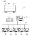
- FIG. 1 A configuration for a conferencing system 10 according to this embodiment is depicted in Fig. 1 .
- This conferencing system 10 is an image display system capable of simultaneous displaying by means of a projector an on-screen display of multiple terminals; the system includes computers PC1 through PC5, a moderator's computer PCm, and a projector PR1 which are connected on a prescribed communication channel.
- the computers PC1 through PC5, the moderator's computer PCm, and the projector PR1 are connected on a local area network LAN. While not shown in the drawing, other devices equivalent to the moderator's computer PCm and the projector PR1 are installed on the local area network LAN as well.
- connection of the computers PC1 through PC5, the moderator's computer PCm, and the projector PR1 is not limited to the mode described above, and various other connection methods could be set up depending on the work environment, required communication speed, and other considerations.
- a local connection such as a D-sub cable or USB cable connection, between the moderator's computer PCm and the projector PR1.
- Connections are not limited to wired connections, and wireless connections may be employed as well. Naturally, connections via the Internet would be possible as well.
- the projector PR1 is capable of displaying through projection onto a screen SC1 a synthesized image that has been created by the moderator's computer PCm synthesizing four different images into a single screen image.
- the four areas of the split-screen display on the screen SC1 will be denoted as split-screen areas SC11 through SC14, as shown in the drawings.
- the computer PC1 in the conferencing system 10 is a personal computer on which prescribed programs have been installed, and is provided for use by a certain Student A.
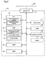
- the general configuration of the computer PC1 is depicted in Fig. 2 .
- Computers PC2 to PC5 which have been provided for use by Students B to E are comparable in configuration to the computer PC1 and as such need not be discussed here.
- the computer PC1 includes a CPU 20, a hard disk drive 30, a ROM 36, a RAM 38, a network interface 41, an input system 51, a VRAM 61, a graphics controller 63, and a display 65, which are respectively interconnected via a bus.
- the CPU 20 performs control of the computer PC1 by loading into RAM 38 firmware or an OS which is stored on the hard disk drive 30 or in the ROM 36, and then executing it. Also, through execution of programs stored on the hard disk drive 30 the CPU 20 can function as a data transmission module 21 or as a communications module 22. These function modules will be discussed in detail later.
- the hard disk drive 30 contains memory areas set aside for storing, in addition to the IP address of the computer PC1, an address/server name management table 31, a server name profile 32, and an hourly profile 83. These elements will be discussed in detail later. These memory areas are not limited to being provided on the hard disk drive 30, and may instead be set aside in EEPROM, a type of rewritable nonvolatile memory.
- the network interface 41 constitutes the interface for connection to the local area network LAN; the computer PC1 is connected to the local area network LAN via this network interface 41.
- the input system 51 includes a keyboard and a pointing device (a mouse in this example).
- the graphics controller 63 using the VRAM 61 as a buffer, displays images intended to be shown on the display 65.
- the moderator's computer PCm in the conferencing system 10 is a personal computer on which prescribed programs have been installed, and is provided for use by an Instructor M.
- this moderator's computer PCm corresponds to the element of the server in the claims.
- the general configuration of the moderator's computer PCm is depicted in Fig. 3 .
- the moderator's computer PCm includes a CPU 70, a hard disk drive 80, a ROM 86, a RAM 88, a network interface 91, a USB interface 93, an input system 101, a VRAM 111, a graphics controller 113, and a display 115, which are respectively interconnected via a bus.
- the CPU 70 can function as a data communications control module 71, an image synthesis module 72, a synthesized image reception module 73, an image toggling reception module 74, GUI control module 75, a communications module 76, a transmission instruction reception module 77, and a completed synthesis alert module 78.
- These function modules will be discussed in detail later.
- the transmission instruction reception module 77 and the completed synthesis alert module 78 are function modules provided in an alternative embodiment, described later.
- the hard disk drive 80 contains memory areas set aside for storing, in addition to the IP address of the moderator's computer PCm, an address/client name management table 81, a client name profile 82, an hourly profile 83, and a class makeup profile 84. These elements will be discussed in detail later. A number of GUI programs, discussed later, are stored as well. These will be discussed in detail later. These memory areas are not limited to being provided on the hard disk drive 80, and may instead be set aside in EEPROM, a type of rewritable nonvolatile memory.
- the USB interface 93 is a USB compliant interface for connection to the projector PR1, and the moderator's computer PCm is connectable to the projector PR1 with a USB cable.
- the ROM 86, the RAM 88, the network interface 91, the input system 101, the VRAM 111, the graphics controller 113, and the display 115 are similar in design to those of the computers PC1 -PC5, and need not be described in detail.
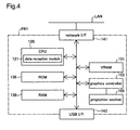
- the projector PR1 in the conferencing system 10 is a conventional projector lacking any special split-screen display capability; its general configuration is depicted in Fig. 4 .
- the projector PR1 includes a CPU 120, a ROM 136, a RAM 138, a network interface 141, a USB interface 143, a VRAM 151, a graphics controller 153, and a projection section 155, which are respectively interconnected via a bus.
- the CPU 120 can function as a data reception module 121. This function module will be discussed in detail later.
- the network interface 141 is an interface for connection to the local area network LAN; the projector PR1 is connected to local area network LAN through this network interface 141.
- the USB interface 143 is a USB-compliant interface for connection to the moderator's computer PCm, and the projector PR1 is connectable to the moderator's computer PCm with a USB cable.
- the graphics controller 153 controls the projection section 155 to project images.
- the projection section 155 is an LCD projection system that displays images on the screen SC1 by projecting light that has passed through liquid crystal panels for each of the RGB color components. While LCD technology is employed in this embodiment, no particular limitation to this technology is implied thereby, and it would be possible to use other technologies such as a CRT, DLP, LCOS, or GLV technology.
- the Instructor M in his or her capacity as the facilitator of the lesson will control the moderator's computer PCm, and via the projector PR1 will display on the screen SC1 in full-screen display any of the on-screen display images PCT1 - PCT5 shown on the display 65 of each of the computers PCT1 -PCT5 being used by the Students A -E, or the on-screen display image PCTm shown on the display 115 of the moderator's computer PCm; or a split-screen display that shows selected on-screen display images from among the on-screen display images PCT1 -PTC5 and PCTm.
- the on-screen display images PCT1 -PTC5 and PCTm are images that show data created respectively by the Students A - E and the Instructor M; depending on the circumstances of the lesson, the Students A -E and the Instructor M may take turns explaining the data they have individually created.
- initial setup refers to the initial setup for the purpose of communication among the computers PC1 -PC5 and the moderator's computer PCm.
- the initial setup process is initiated when, first, the Instructor M launches a prescribed software application, and each Student A - E then launches the prescribed software application.
- the CPU 20 of each of the computers PC1 -PC5 will issue a search command for global broadcast onto the local area network LAN.
- the CPU 70 of the moderator's computer PCm having received the search command will reply to each of the computers PC1 -PC5 with the computer name (instructor name) and IP address of the moderator's computer PCm.
- the computers PC1 -PC5 upon receipt of the computer name and IP address, will register the information in the address/server name management table 31.
- the CPU 20 of each of the computers PC1 -PC5 will then individually transmit the computer name (student name) and IP address of its computer PC1 -PC5 to the moderator's computer PCm. Upon receipt of these computer names and IP addresses, the moderator's computer PCm will register them in the address/client name management table 81.
- the computers PC1 -PC5 will identify the IP address of the moderator's computer PCm and establish communication.
- the moderator's computer PCm will identify the IP addresses of the computers PC1 -PC5 and establish communication.
- this initial setup process is designed to be carried out each time that aforementioned software application is launched in order to deal with instances in which a new student has been added or an IP address has changed; however, it is possible to dispense with this updating of initial setup in instances where there has been no change in registration over a prescribed time period.
- the initial setup process described above may also be designed to be input by the Instructor M and the Students A -E using the input systems 51 and 101.
- IP addresses of the computers PC1 -PC5 and the moderator's computer PCm have been saved on the respective hard disk drives of the computers by being set beforehand by the Students A -E and the Instructor M; however, no particular limitation to such a mode is intended. For example, it would be acceptable, prior to the initial setup described above, for a DHCP server on the local area network LAN to receive IP address requests globally broadcast by the computers PC1 - PC5 and by the moderator's computer PCm, and to individually assign IP addresses.
- Fig. 5 and Fig. 6 depict the flow of the process establishing connections among the computers PC1 -PC5 and the moderator's computer PCm.
- Fig. 5 depicts the process carried out on the computer PC1 -PC5 side by the CPU 20 through a process in its capacity as the communications module 22.
- Fig. 6 depicts the process carried out on the moderator's computer PCm side by the CPU 70 through a process in its capacity as the communications module 76.
- the description below assumes that the Students A -E have been assigned computers for their own exclusive use. These processes will be initiated upon launch of the aforementioned software application and completion of initial setup.
- Step S200 the CPU 20 of each of the computers PC1 -PC5 will load the hourly profile 33 stored on the hard disk drive 30, as depicted in Fig. 5 (Step S200).
- the hourly profile 33 is a profile that establishes access points on a hourly basis; in this case, lesson time slots for first period to fourth period Monday through Friday are associated with names of the instructors of the lessons taking place in those lesson time slots. That is, the hourly profile 33 represents a lesson schedule for the Students A -E, specifying for example that first period on Mondays will be taught by Instructor M, and that third period on Tuesdays will be taught by Instructor N. This hourly profile 33 will have been input beforehand by each Student A -E using the input system 51, and stored on the hard disk 30.
- the CPU 20 will compare the current time with the hourly profile 33 and decide whether there is any profile data corresponding to the current time (Step S201).
- Step S201 YES
- this will mean that lesson attendance has been scheduled for the time in question, and the CPU 20 will accordingly request a connection to the computer (in this embodiment, the moderator's computer PCm) of the instructor in question (in this embodiment, Instructor M), at the time in question (Step S202).
- the computer in this embodiment, the moderator's computer PCm
- Instructors N to Q shown in Fig. 7 also have individually assigned moderator's computers that are connected to the local area network LAN, and if there are times at which other lessons have been scheduled, requests will be made to connect to the computers of Instructors N to Q.
- Step S201: NO this will mean that no lesson has been scheduled for the time in question, and the process will terminate.
- the hourly profile 83 is a profile that establishes access points on a hourly basis; in this case, lesson time slots for first period to fourth period Monday through Friday are associated with the names of the lessons to be taught in those lesson time slots. That is, the hourly profile 83 represents a teaching schedule for Instructor M, specifying for example that he or she will teach Class 1 during first period on Mondays, and will teach Class 2 during second period on Mondays.
- the class makeup profile 84 is a profile indicating the makeup of classes on an individual lecture attendance basis; here, the names of the students making up the class in question have been associated respectively with Class 1 to Class 7.
- This hourly profile 83 and the class makeup profile 84 will have been input beforehand by Instructor M, and stored on the hard disk drive 80.
- the CPU 70 will decide on an ongoing basis whether connection requests have been made by the Students A -E, i.e. by the computers PC1 - PC5 (Step S222).
- Step S222 if no connection request has been made (Step S222: NO), it will await a connection request. If on the other hand it is decided that a connection request has been made (Step S222: YES), the CPU 70 will refer to the hourly profile 83 and to the class makeup profile 84 in order to decide whether the student making the connection request is a student belonging to the class that corresponds to the current time specified in the hourly profile 83 (Step S223).
- Step S223 YES
- the CPU 70 will allow connection in response to the connection request from the student, and a connection will be set up (Step S224). If on the other hand the student does not belong to the class, since the student in question is not authorized to attend the lesson being held at this time, the CPU 70 will refuse the connection request from the student (Step S225), whereupon the process will return to the aforementioned Step S222 and await a new connection request from a student. In this way, connections between the computers PC1 - PC5 and the moderator's computer PCm are set up via the local area network LAN.
- Step S200 the CPU 20 will prompt the student to enter his or her name, and in the aforementioned Step S202 will transmit the student's name, together with the connection request, to the moderator's computer PCm.
- profiles are stored only by the moderator's computer PCm
- the moderator's computer PCm will be able to look up in the hourly profile 83 and the class makeup profile 84, and allow connections only for the computers PC1 -PC5 that match these profiles, thereby making it possible for connections between the computers PC1-PC5 and the moderator's computer PCm to be set up automatically.
- Step S225 it would be acceptable to employ an arrangement whereby if the moderator's computer PCm refuses a connection in Step S225, the computer PC1 -PC5 that was refused the connection will be notified of the refused connection. By so doing, the Student A -E may rapidly be apprised that he or she is not authorized to attend the lesson in question.
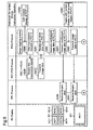
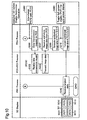
- Fig. 9 and Fig. 10 depict an exemplary flow of a split-screen display switching process in which the conferencing system 10 of the embodiment is used to project the on-screen displays of the computers PC1 -PC5 onto the screen SC1 as a split-screen display image while switching among the on-screen displays.
- the right column in Fig. 9 and Fig. 10 depicts operations performed by the Instructor M using the moderator's computer PCm, to specify on-screen displays for projection onto the screen SC1.
- FIG. 10 depict processes of the moderator's computer PCm in response to the operations performed by the Instructor M shown in the right column, and processes of the computers PC1 -PC5 and in the projector PR1 in response to the processes of the moderator's computer PCm.
- the left columns in Fig. 9 and Fig. 10 depict the images projected onto the screen at each stage of the processes shown in the middle columns.
- the instruction operation is one instructing the projector PR1 to project on-screen display images PCT1 -PCT4 of the computers PC1 -PC4, in the form of four split-screen images (Operation 0360).
- Operation 0360 is specified using the input system 101, and a GUI (graphical user interface) that is displayed on the display 115 of the moderator's computer PCm.
- GUI graphical user interface
- the CPU 70 will use the graphics controller 113 to bring up on the display 115 a window for selecting the projector and for making on-screen display settings.
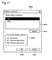
- Fig. 11 depicts a Projector Selection window W400 as an example of such a window.
- the Projector Selection window W400 includes a projector selection sub-window 410 and an on-screen display settings sub-window W420.
- the projector selection sub-window 410 displays a list of the projectors connected to the moderator's computer PCm.
- the projectors displayed here are projectors whose connection to the moderator's computer PCm have been recognized automatically through plug-and-play.
- Fig. 11 depicts the projector PR1 selected as the projector for use from among the connected projectors PR1 and PR2. While not shown in Fig. 1 , for the purposes of this example the projector PR2 is assumed to be connected on the local area network LAN through a configuration similar to the projector PR1.
- the aforementioned list of projectors in the projector selection sub-window 410 will show the results of a search by the CPU 70 for projectors when the software application is launched; however, by clicking on a Search button B412 it will be possible to search again for connected projectors.
- the on-screen display settings sub-window W420 shows display options for images to be displayed on the screen SC1 by the projector PR1.
- the options are full screen display, two-screen display, and four-screen display; of these, the four-screen display option is depicted as having been selected.
- Two-screen display and four-screen display represent display options whereby different images will be displayed simultaneously in split-screen display. By selecting from among these display modes it is a simple matter to switch between split-screen display and full-screen display; a detailed discussion will follow later.
- the options for split-screen display are not limited to two-screen display and four-screen display shown here by way of example; naturally, a three-screen display, or a display of five or more screens, would be acceptable as well.
- Fig. 12 depicts a Projector Operation window W500 as one example of such a window.
- the Projector Operation window W500 includes a moderator indicator sub-window W510, a participant indicator sub-window W520, a Projector Operation sub-window W600, and a Preview sub-window W700.
- the moderator indicator sub-window W510 shows as the moderator's name the name of the predetermined user of the moderator's computer PCm. Where the moderator's computer PCm is shared among multiple users, the moderator may be prompted to input his or her name at launch of the software application.
- the participant indicator sub-window W520 shows a list of computers enabled for projection by the projector PR1, as well as the status of each of these.
- a projection-enabled computer refers to a computer with which a connection with the moderator's computer PCm was set up in the aforementioned Step S224 and the moderator's computer PCm.
- the computers are designated by the name of the user of the computer in question, for convenience in identification.
- Status refers to information indicating whether a computer is currently being projected.
- the moderator indicator sub-window W510 displays the moderator name "Instructor M"
- the participant indicator sub-window W520 displays "Student A - E" using computers PC1 - PC5.
- the displays of the moderator indicator sub-window W510 and the participant indicator sub-window W520 could be displayed instead.
- the Projector Operation sub-window W600 includes an upper left screen sub-window W610, an upper right screen sub-window W620, a lower right screen sub-window W630, and a lower left screen sub-window W640.
- the reason that four screen sub-windows are provided here is that "four-screen display” was selected from the on-screen display settings sub-window W420 discussed previously; if "two-screen display” had been selected, the number of screen sub-windows would be two, and if "full-screen display” had been selected, the number of screen sub-windows would be one. That is, the number and placement of the screen sub-windows provided in the Projector Operation sub-window W600 will correspond to the split-screen display shown on the screen SC1.
- screen sub-windows are associated with a specific number of divided areas and placement thereof within the split-screen display; however, no particular limitation is imposed thereby and sub-windows may instead be associated with various other split-screen display modes. For example, where individual split screen constituent areas making up a split-screen display are shown with screen borders of different colors, the colors of the corresponding screen sub-windows could be associated with the colors of these borders; or where individual split screen constituent areas differ from one another in shape or size, the shape or size of the corresponding screen sub-windows could be associated with the shape or size of these split screen constituent areas.
- the upper left screen sub-window W610 includes a projector user indicator field D611; a Project button B613; a Quit button B614; and a Full Screen Display button B615.
- the projector user indicator field D611 is field that indicates the user of the computer that corresponds to the image for display in the upper left split-screen display area (the split screen constituent area SC11).
- the Project button B613 and the Quit button B614 are control buttons used to start and stop projecting a prescribed image in the upper left split-screen display area, independently of other split-screen display areas. For example, with "Student A" selected in the participant indicator sub-window W520 as depicted in Fig.
- the operation of selecting "Student A" from the participant indicator sub-window W520 and assigning the screen display image PCT1 to the split screen constituent area SC11 from the Projector Operation sub-window W600 may be accomplished by dragging and dropping "Student A" into W610 in the participant indicator sub-window W520, rather than clicking on the Project button B613.
- the Full Screen Display button B615 is a button used to toggle between the four-screen split-screen display and the full-screen display. For example, if the four-screen split-screen display is currently being displayed on the screen SC1, clicking the Full Screen Display button B615 will toggle the image displayed in the upper left split screen area to full-screen display. Clicking the Full Screen Display button B615 again will toggle back from full-screen display to the original four-screen split-screen display. Since the upper right screen windows W620 -W640 are similar to the upper left screen window 610, they will not be discussed here.
- the Projector Operation sub-window W600 includes a PLAY button B601, a STOP button B602, and a PAUSE button B603 for controlling projection operation of the projector PR1. These buttons are used to perform collective operations on images transmitted to the projector PR1 by the moderator's computer PCm, and they permit images projected by the projector PR1 to be played, stopped, or paused through collective operations, regardless of whether the display on the screen SC1 is currently a split-screen display or a full-screen display.
- the Preview sub-window W700 is an area that, when any of the Students A - E displayed in the participant indicator sub-window W520 have been selected, provides a preview of the on-screen display image PCT1 - PCT5 that corresponds to the selected student, irrespective of the image projected by the projector PR1; it is possible to enlarge or shrink the display using an Enlarge button B701 or a Shrink button B702 provided for this purpose.
- the preview function may employ, for example, image data of reduced data size that was received from the computers PC1 -PC5 by the moderator's computer PCm sending data transmission requests to the computers PC1 -PC5 when the Students A - E are selected from the participant indicator sub-window W520.
- the Projector Operation window W500 provided with these sub-windows further includes a Select Projector button B501 and a Configuration button B502.
- the Select Projector button B501 is a button for selecting a projector and for resetting the on-screen display; clicking this button will bring up the Projector Selection window W400 discussed earlier. Accordingly, by clicking the Select Projector button B501 to bring up the Projector Selection window W400 it will be possible for the Instructor M to select a projector or to modify the on-screen display settings even while the conferencing system 10 is currently in use.
- the Configuration button B502 is a button for configuring settings such as whether to use the input history to the projector PR1.
- the subsequently displayed Projector Operation window W500 will change to reflect these changes. For example, if from the Projector Selection window W400 an operation is performed to switch from four-screen display to two-screen display, the CPU 70 through a process in its capacity as the GUI control module 75 will load from among the GUI programs stored on the hard disk drive 80 the GUI program that corresponds to two-screen display, and will display the Projector Operation window W500 that now includes a Projector Operation sub-window W600 composed of two screen sub-windows. Where, the screen sub-windows have been associated with the display modes of split-screen display color, shape, or size as mentioned above, the Projector Operation sub-window W600 may be modified to reflect the changes in display mode.
- the screen sub-windows W610 - W640 that make up the Projector Operation sub-window W600 display thumbnails that the CPU 70 has created on the basis of image data for display in the corresponding split-screen display area and stored in the RAM 88.
- the screen sub-windows W610 -W640 may be provided with display fields for displaying the thumbnails, at locations that will not interfere with the buttons etc.; or semitransparent thumbnails created by dimming the luminance signal may be displayed superposed over the buttons etc. This will make it easier to ascertain relationships between split-screen display areas and the screen sub-windows W610 -W640, affording simpler operation.
- the Instructor M selects "Student A" from the participant indicator sub-window W520, and after confirming the content of the on-screen display image PCT1 displayed in the Preview sub-window W700, clicks the Project button B613 of the upper left screen sub-window W610.
- the instructor will click the Project button B623 -B643 in each of the corresponding upper right screen sub-windows W620 -W640.
- the purpose of this operation is to instruct projection of the screen display images PCT1 -PCT4 of the computers PC1 -PC4 in a four-screen split-screen display by the projector PR1.
- These instructions will be handled by the CPU 70 through a process in its capacity as the synthesized image reception module 73.
- the CPU 70 of the moderator's computer PCm will send a sequence of data transmission requests to the computers PC1-PC4 (Step S300).
- Step S320 upon receipt of the data transmission request sent by the moderator's computer PCm (Step S320), the CPU 20 of each of the computers PC1 -PC4, through a process in its capacity as the data transmission module 21, will transmit to the moderator's computer PCm image data of the on-screen display image PCT1 -PCT4 displayed on its individual display 65 (Step S321).
- This image data of the on-screen display images PCT1 -PCT4 represents image data (here, RGB image data) that was saved in the RAM 61 of the computer PC1 -PC4 at the time that the data transmission request was received, and will be transmitted together with settings information for the graphics controller 63 necessary for the image data to be displayed in image form.
- Settings information for the graphics controller 63 need not be transmitted if the graphics controller 63 of each of the computers PC1 -PC4, the graphics controller 113 of the moderator's computer PCm, and the graphics controller 153 of the projector PR1 have standardized settings.
- the CPU 70 of the moderator's computer PCm through a process in its capacity as the data communications control module 71 will receive the image data of the on-screen display images PCT1 -PCT4 respectively transmitted by the computers PC1 -PC4, and save it in the RAM 85 in association with the name of the computer (Step S301).
- the CPU 70 will then generate in the RAM 85 synthesized image data representing a synthesized image of the on-screen display images PCT1-PCT4 (Step S302).
- the CPU 70 will transmit the synthesized image data of the on-screen display images PCT1-PCT4 to the projector PR1 (Step S304).
- the CPU 120 will receive the synthesized image data of the on-screen display images PCT1 -PCT4, and record it to the VRAM 151.
- the graphics controller 153 will then read the image data from the VRAM 151 and will project the image onto the screen SC1 using the projection section 155 (Step S340).
- a four-screen split-screen showing the respective on-screen display images PCT1-PCT4 will be displayed on the screen SC1.
- the Projector Operation window W500 discussed above will assume a condition like that depicted in Fig. 13 .
- the participant indicator sub-window W520 "Currently projecting" status is shown for the Students A -D.
- the Projector Operation sub-window W600 "Students A -D" are respectively shown in the projector user indicator fields D611 -D641.
- the Preview sub-window W700 the on-screen display image PCT4 which corresponds to the last-selected Student D is shown in the participant indicator sub-window W520.
- Step S302 and Step S304 the synthesized image data was transmitted after the CPU 70 has received image data from all of the computers PC1 -PCT4 and had generated the synthesized image data; however, generation and transmission of the synthesized image data may take place at prescribed timing intervals as well.
- the four-screen split-screen display image will appear suddenly on the screen SC1; whereas in the latter instance, the images will be displayed progressively in the course of generating the four-screen split-screen display.
- the Instructor M will operate the input system 101 to instruct toggling of the image projected onto the screen SC1 from the four-screen split-screen display image of the on-screen display images PCT1 -PCT4 to a full-screen display of the on-screen display image PCT1 of the computer PC1 (Operation 0361). Specifically, from the Projector Operation window W500 displayed on the display 115 of the moderator's computer PCm, the Instructor M will click on the Full Screen Display button B615 of the upper left screen sub-window W610.
- Step S305 Upon receiving this instruction, in the moderator's computer PCm, through a process in its capacity as the image toggling reception module 74 the CPU 70 will receive the instruction; and through a process in its capacity as the data communications control module 71 will transmit the image data of the on-screen display image PCT1 recorded in the RAM 85 in association with the name of the computer PC1 to the projector PR1 (Step S305).
- the CPU 120 through a process in its capacity as the data reception module 121 will receive the image data of the on-screen display image PCT1 sent by the moderator's computer PCm, and in the same manner as in Step S340 discussed previously, will project the image onto the screen SC1 (Step S341).
- the on-screen display image PCT1 will be displayed in full-screen display on the screen SC1.
- the Instructor M will project the on-screen display image PCT1 in full-screen display onto the screen SC1, and while the Student A is explaining the on-screen display image PCT1, will control the input system 101 to instruct creation of synthesized image data in which, of the synthesized image data of the screen display images PCT1 -PCT4, the on-screen display image PCT5 is interchanged with the on-screen display image PCT2 (Operation 0362).
- the Instructor M will click on the Quit button B624 of the upper right screen sub-window W620 that corresponds to the split-screen display area of the on-screen display image PCT2; and then from the participant indicator sub-window W520 will select "Student E" and click on the Project button B823 of the upper right screen sub-window W620.
- This operation is in preparation for split-screen display of the on-screen display images PCT1, 5, 3, and 4 after explanation of the on-screen display image PCT1 has been completed.
- the CPU 70 of the moderator's computer PCm Upon receiving this instruction, the CPU 70 of the moderator's computer PCm, through a process in its capacity as the synthesized image reception module 73, will receive the instruction, and through lookup in the client name profile 82 and the hourly profile 83 will identify the IP address of the other device, and send a data transmission request to the computer PC5 (Step S306).
- Step S322 upon receipt of the data transmission request sent by the moderator's computer PCm (Step S322), the CPU 20 of the computer PC5 through a process in its capacity as the data transmission module 21 will transmit the image data of the on-screen display image PCT5 currently displayed on the display 65 to the moderator's computer PCm (Step S323).
- transmission of this image data in Step S323 and Step S321 may take place in a compressed format such as JPEG.
- the CPU 70 of the moderator's computer PCm upon receipt of the transmission from the computer PC5, through a process in its capacity as the data communications control module 71 the CPU 70 of the moderator's computer PCm will receive the image data of the on-screen display image PCT5 sent by the computer PC5, and will save it to the RAM 85 in association with the computer name (Step S307).
- the CPU 70 will generate from the image data of the on-screen display images PCT1, 5, 3, and 4 that was saved in the RAM 85 synthesized image data that represents a synthesized image of the on-screen display images PCT1, 5, 3, and 4, and will record this data to the RAM 85 (Step S308).
- the Instructor M will control the input system 101 to instruct toggling of the image being projected onto the screen SC1, from full-screen display of the on-screen display image PCT to split-screen display (Operation 0363). Specifically, from the Projector Operation window W500 displayed on the display 115 of the moderator's computer PCm, the Instructor M will click on the Full Screen Display button B615 of the upper left screen sub-window W610.
- the CPU 70 of the moderator's computer PCm Upon receiving this instruction, the CPU 70 of the moderator's computer PCm, through a process in its capacity as the image toggling reception module 74, will receive the instruction, and then through a process in its capacity as the data communications control module 71 will send to the projector PR1 the synthesized image data of the on-screen display images PCT1, 5, 3, 4 that was recorded in the RAM 85 (Step S310).
- Step S342 the CPU 120 will receive the synthesized image data of the on-screen display images PCT1, 5, 3, 4, and in the same manner as in the aforementioned Step S340 and Step S341 will project the image onto the screen SC1 (Step S342).
- Step S342 a four-screen split-screen showing the respective on-screen display images PCT1, 5, 3, and 4 will be displayed in the split-screen areas SC11-SC14. This completes the screen toggling process of the embodiment.
- the computers PC1 -PC5 in response to a data transmission request from the moderator's computer PCm, the computers PC1 -PC5 will send to the moderator's computer PCm image data recorded in the VRAM 61 at the time that the transmission request was received; however, no limitation to such an arrangement is intended.
- the computers PC1 -PC5 could instead at periodic intervals transmit image data recorded in the VRAM 61 to the moderator's computer PCm.
- data could be transmitted to the moderator's computer PCm each time that data in the VRAM 61 is updated.
- the on-screen display images PCT1-PCT5 of the computers PC1 -PC5 constitute the images for projection onto the screen SC1, but no limitation is intended thereby and it would be acceptable to display any other image handled by the computers PC1 -PC5.
- the computers PC1 -PC5 are equipped with webcams, images taken thereby could be projected.
- a projector was described by way of the image display device included in the conferencing system 10, but various other types of display devices, such as a plasma display, liquid crystal display, organic EL display or the like could be used as well.
- the computers PC1 -PC5 were described as the terminals included in the conferencing system 10, the terminals could be composed of various other kinds of communications terminals such as mobile phones, PDAs (Personal Digital Assistant), and so on.
- the moderator's computer PCm functioned as the server for receiving image data from the computers PC1 -PC5, generating synthesized images, transmitting these the projector PR1 and so on; however, the moderator's computer PCm operated by the Instructor M and the server may be provided as separate devices. This can reduce the load on the moderator's computer PCm, and enhance the usage capabilities of the moderator's computer PCm.
- the hourly profiles saved on the hard disks 30 of the computers PC1 -PC5, as well as the hourly profile 83 and the class makeup profile 84 stored on the hard disk 80 of the moderator's computer PCm may be managed by the server instead. This will enable the schedules of the Instructor M and the Students A -E, the makeup of each class, and so on to be managed in an integrated fashion, making management easier.
- the conferencing system 10 of the above configuration uses image data of images handled by the computers PC1 -PC5 and received by the moderator's computer PCm from the computers PC1 -PC5, as well as image data of images handled by the moderator's computer PCm, the conferencing system 10 of the above configuration generates synthesized image data and transmits the data to the projector PR1. Consequently, the projector PR1 can display a synthesized image simply by displaying the synthesized image data it has received. That is, utilizing an existing projector PR1 that lacks any special split-screen display functionality, it is possible for images handled by the computers PC1 -PC5 and by the moderator's computer PCm which are connected on the local area network LAN to be displayed as a single split-screen display. Additionally, through simple operation using the moderator's computer PCm, the operator of the moderator's computer PCm will be able to display desired images from his or her own computer as well, without the need to operate a separate terminal.
- the conferencing system 10 can switch the image data transmitted to the projector PR1 by the data communications control module 71 of the moderator's computer PCm between synthesized image data, and image data handled by any of the computers PC1 -PC5 or by the moderator's computer PCm. Consequently, users will be able to conference while displaying a synthesized image, an image handled by any of the computers PC1 -PC5, or an image handled by the moderator's computer PCm, as conditions warrant.
- the conferencing system 10 of the above configuration can generate desired synthesized images through operation of the moderator's computer PCm, and once generation of the image is finished can toggle the display on the screen SC1 from full-screen display to split-screen display in order to display the image of the synthesized image data thusly created; accordingly, during switching between screens, it will be possible to avoid unnecessary wait time for the synthesized image data to be generated and displayed, so the discussion can continue uninterrupted.
- the conference may therefore proceed smoothly.
- the moderator's computer PCm is provided with a unit for receiving an instruction to transmit image data to the projector PR1, and a unit for alerting the user of the moderator's computer PCm when generation of the synthesized image is done. This difference will be discussed in detail below.
- Fig. 14 and Fig. 15 are illustrations depicting exemplary flow of a split-screen display toggling process in the alternative embodiment.
- process steps comparable to those in the embodiment have been assigned the same symbols as in the embodiment, and are not discussed in any detail.
- This process will be initiated when the Instructor M instructs the moderator's computer PCm to generate synthesized image data that represents the on-screen display images PCT1 -PCT4 of the computers PC1 - PC4 as a four-screen split-screen display image (Operation 0380). While the Operation 0360 in the embodiment was an operation for instructing both generation and transmission of synthesized image data, this operation differs from the Operation 0360 in that it instruct only generation of the synthesized image data.
- the above Operation 0380 is carried out through a method comparable to the Operation 0360 in the embodiment.
- the GUI employed in this alternative embodiment has a few differences from that in the previous embodiment.
- a specific example of the Projector Operation window W500 employed in the alternative embodiment is depicted in Fig. 16 .
- a point of difference from the embodiment is that the Projector Operation sub-window W600 included in the Projector Operation window W500 has a Send button B605 and a completed image synthesis indicator field D607. These will be discussed in detail later.
- the CPU 70 When an instruction to generate synthesized image data is received, the CPU 70 will receive image data from the computers PC1 -PC4, and will generate synthesized image data of the on-screen display images PCT1 -PCT4 (Steps S300 -S302, S320, 321). When generation of the synthesized image data is finished, through a process in its capacity as the completed synthesis alert module 78 the CPU 70 will alert the user of the moderator's computer PCm, i.e. the Instructor M, when generation of the synthesized image data is done (Step S303). Specifically, the message "Image Synthesis Done" will appear in the completed image synthesis indicator field D607, for example.
- Step S303 that generation of the synthesized image data is finished, the Instructor M will now use the input system 101 to click on the Send button B605 and instruct that the synthesized image data so generated be sent to the projector PR1 (0381).
- the CPU 70 of the moderator's computer PCm Upon receiving this Send instruction, through a process in its capacity as the transmission instruction reception module 77 the CPU 70 of the moderator's computer PCm will transmit the generated synthesized image data to the projector PR1 for display of the on-screen display images PCT1 - PCT4 in four-screen split-screen display (Steps S304, S340).
- the Instructor M will instruct the moderator's computer PCm to create, from the synthesized image data of the on-screen display images PCT1 -PCT4, synthesized image data in which the on-screen display image PCT2 is replaced by the on-screen display image PCT5 (Operation 0382).
- the CPU 70 of the moderator's computer PCm will receive the image data of the on-screen display image PCT5 from the computer PC5, and generate synthesized image data representing a synthesized image of the on-screen display images PCT1, 5, 3, and 4 (Steps S306 -S308, S322, S323).
- Step S309 the completed image synthesis indicator field D607 can be used as the specific method of alert.
- Step S309 that generation of the synthesized image data is finished
- the Instructor M will now use the input system 101 to click on the Send button B605 and instruct that the synthesized image data so generated be sent to the projector PR1 (0383).
- the CPU 70 of the moderator's computer PCm Upon receiving this Send instruction, through a process in its capacity as the transmission instruction reception module 77, the CPU 70 of the moderator's computer PCm will transmit the generated synthesized image data to the projector PR1 for display of the on-screen display images PCT1, 5, 3, and 4 in four-screen split-screen display (Steps S310, S342).
- the completed image synthesis indicator field D607 of the Projector Operation sub-window W600 is employed as the unit by which the CPU 70 notifies the Instructor M when generation of synthesized image data is done; however, no limitation to this particular mode is intended.
- the CPU 70 could instead look up in the RAM 88 and display the generation conditions of the synthesized image data in the Preview sub-window W700. With such a mode as this as well, the Instructor M can be apprised when generation of the synthesized image data is done.
- the moderator's computer PCm will transmit display data only upon receiving an instruction to transmit image data to the projector PR1. Consequently, synthesized image data representing a new split-screen display (e.g. on-screen display images PCT1, 5, 3, 4) can be generated through a process separate from the previous display, while the projector PR1 is still displaying the previous prescribed split-screen display (e.g. in-screen display images PCT1 - PCT4). Then, after generation of the new display is finished, once an instruction to send the synthesized image data to the projector PR1 is received, when toggling from the previous prescribed split-screen display to the new split-screen display it will be possible to avoid unnecessary wait time before the synthesized image data is generated and displayed.
- synthesized image data representing a new split-screen display e.g. on-screen display images PCT1, 5, 3, 4
- the previous prescribed split-screen display e.g. in-screen display images PCT1 - PCT4
- the moderator's computer PCm alerts the user of the moderator's computer PCm when generation of the synthesized image data is finished
- the user of the moderator's computer PCm can switch the display image after being apprised that generation of the synthesized image data is finished. Consequently, when switching between display images, it will be possible to make this switch while accurately estimating the timing in such a way as to avoid unnecessary wait time to generate and display the image data.
- One such mode is a conferencing system as set forth above, wherein the terminals are composed of a plurality of terminals; the reception unit receives terminal image data from at least two of the plurality of terminals; and the other image includes an image represented by at least one set of image data from among the received terminal image data from at least two terminals.
- the terminals are composed of multiple terminals, and the reception unit receives respective terminal image data from at least two terminals among the plurality of terminals, images handled by the plurality of terminals can be displayed in a single split-screen display.
- the other image may include an image handled by the server.
- an image handled by a terminal and an images handled by the server can be displayed a single split-screen display. Consequently, through simple operation using the server, the user of the server will be able to display a desired image from his or her own computer as well, without the need to operate a separate terminal.
- the second transmission unit may include a switching unit that switches the transmitted data for display from the synthesized image data to the terminal image data received by the reception unit, or to server image data representing an image handled by the server.
- the second transmission unit includes a switching unit for switching the transmitted display data from the synthesized image data to the terminal image data or to server image data, users can conference while displaying either a synthesized image, a terminal image, or a server image as conditions warrant.
- the server may further include a first reception unit that receives an instruction to switch the data for display; and the second transmission unit may switch the data for display on the basis of an instruction received by the first reception unit.
- the server receives an instruction to switch the data for display, and switched the data for display depending on this instruction. Consequently, the user can toggle among displayed images as conditions of the conference warrant, and the conference can proceed smoothly and in a highly flexible manner.
- the image synthesis unit may generate new synthesized image data when the second transmission unit has switched the data for display from the synthesized image data to the terminal image data or to the server image data.
- new synthesized image data will be generated when the data for display has been switched from synthesized image data to terminal image data or to server image data. Consequently, during the time that the image display device is displaying the terminal image or the server image, new synthesized image data can be generated; and once generation thereof is finished, by then switching the data for display to the new synthesized image and displaying the new synthesized image, it will be possible to avoid unnecessary wait time for generating and displaying the synthesized image data when the display image is switched.
- the server may further include a second reception unit that receives an instruction to transmit the data for display to the image display device; and the second transmission unit may transmit the data for display on the basis of an instruction received by the second reception unit.
- the server receives an instruction to transmit data for display to an image display device, and transmits the data for display on the basis of this instruction. Consequently, during the time that prescribed synthesized image data is being transmitted to image display device as data for display and the synthesized image is being displayed on the image display device, new synthesized image data can be generated; and once generation thereof is finished, by then issuing an instruction to transmit the new synthesized image data to the image display device as data for display, it will be possible to avoid unnecessary wait time for generating and displaying the synthesized image data when the display image is switched.
- the server may further include a unit that alerts the user of the server when generation of the synthesized image data by the synthesis unit is complete.
- the user of the server With a conferencing system having this configuration, the user of the server will be alerted that generation of the synthesized image data by the synthesis unit is finished, and thus the user of the server will be able to switch the displayed image upon confirming that generation of the synthesized image data is finished. Consequently, when switching between display images, it will be possible to make the switch while accurately estimating the timing in such a way as to avoid unnecessary wait time to generate and display the image data.
- the server may further include a third reception unit that receives an instruction to specify images for making up a synthesized image; and the image synthesis unit may generate the synthesized image data on the basis of an instruction received by the third reception unit.
- the server receives an instruction to specify images for inclusion in the synthesized image, and on the basis of the instruction generates synthesized image data. Consequently, the user can toggle among displayed images as conditions of the conference warrant, and the conference can proceed smoothly and in a highly flexible manner.
- the image handled by the terminal may be an image that is displayed on a display screen provided to the terminal.
- a conferencing system having this configuration, since an image displayed on the display screen provided to the terminal can be displayed, the user of a terminal can explain displayed content on the image display device while verifying the display screen of the terminal in question.
Landscapes
- Engineering & Computer Science (AREA)
- Theoretical Computer Science (AREA)
- Signal Processing (AREA)
- General Physics & Mathematics (AREA)
- Computer Networks & Wireless Communication (AREA)
- Physics & Mathematics (AREA)
- General Engineering & Computer Science (AREA)
- Human Computer Interaction (AREA)
- Computer Hardware Design (AREA)
- Multimedia (AREA)
- Controls And Circuits For Display Device (AREA)
- Two-Way Televisions, Distribution Of Moving Picture Or The Like (AREA)
- Digital Computer Display Output (AREA)
Applications Claiming Priority (1)
| Application Number | Priority Date | Filing Date | Title |
|---|---|---|---|
| JP2007205647A JP2009044328A (ja) | 2007-08-07 | 2007-08-07 | 会議システム、サーバ、画像表示方法、コンピュータプログラム及び記録媒体 |
Publications (3)
| Publication Number | Publication Date |
|---|---|
| EP2023630A2 true EP2023630A2 (fr) | 2009-02-11 |
| EP2023630A3 EP2023630A3 (fr) | 2010-12-01 |
| EP2023630B1 EP2023630B1 (fr) | 2018-09-19 |
Family
ID=39930746
Family Applications (1)
| Application Number | Title | Priority Date | Filing Date |
|---|---|---|---|
| EP08252634.4A Active EP2023630B1 (fr) | 2007-08-07 | 2008-08-05 | Système de conference, serveur, methode de visualisation d'image et produit de logiciel d'ordinateur |
Country Status (5)
| Country | Link |
|---|---|
| US (2) | US8984061B2 (fr) |
| EP (1) | EP2023630B1 (fr) |
| JP (1) | JP2009044328A (fr) |
| CN (1) | CN101365097A (fr) |
| BR (1) | BRPI0803498A2 (fr) |
Cited By (4)
| Publication number | Priority date | Publication date | Assignee | Title |
|---|---|---|---|---|
| EP2645622A1 (fr) * | 2012-03-30 | 2013-10-02 | Ricoh Company, Ltd. | Système de traitement dýimages et appareil de traitement dýimages |
| EP3024198A1 (fr) * | 2014-11-21 | 2016-05-25 | Delta Electronics, Inc. | Appareil d'affichage, système vidéo, procédé d'affichage et projecteur |
| US10298678B2 (en) | 2014-02-17 | 2019-05-21 | International Business Machines Corporation | Omnichannel approach to application sharing across different devices |
| EP3917136A1 (fr) * | 2020-05-29 | 2021-12-01 | BenQ Intelligent Technology (Shanghai) Co., Ltd | Procédé et système de commande à deux régions affichage |
Families Citing this family (40)
| Publication number | Priority date | Publication date | Assignee | Title |
|---|---|---|---|---|
| US8074581B2 (en) | 2007-10-12 | 2011-12-13 | Steelcase Inc. | Conference table assembly |
| US8875026B2 (en) | 2008-05-01 | 2014-10-28 | International Business Machines Corporation | Directed communication in a virtual environment |
| US20140361954A1 (en) * | 2013-06-07 | 2014-12-11 | Lewis Epstein | Personal control apparatus and method for sharing information in a collaboration workspace |
| US10631632B2 (en) | 2008-10-13 | 2020-04-28 | Steelcase Inc. | Egalitarian control apparatus and method for sharing information in a collaborative workspace |
| US9639963B2 (en) * | 2008-12-08 | 2017-05-02 | Microsoft Technology Licensing, Llc | Command remoting techniques |
| JP5375338B2 (ja) | 2009-05-29 | 2013-12-25 | セイコーエプソン株式会社 | 画像表示システム、画像表示装置、画像表示方法、画像供給装置、およびプログラム |
| US10884607B1 (en) | 2009-05-29 | 2021-01-05 | Steelcase Inc. | Personal control apparatus and method for sharing information in a collaborative workspace |
| JP5522381B2 (ja) | 2010-03-15 | 2014-06-18 | セイコーエプソン株式会社 | 表示装置、端末装置、表示システム、プログラム、情報記憶媒体、表示方法および画像変更方法 |
| US20120030595A1 (en) * | 2010-07-29 | 2012-02-02 | Seiko Epson Corporation | Information storage medium, terminal apparatus, and image generation method |
| JP5516882B2 (ja) | 2010-07-29 | 2014-06-11 | セイコーエプソン株式会社 | プログラム、情報記憶媒体、端末装置、表示システムおよび画像生成方法 |
| JP2012032508A (ja) * | 2010-07-29 | 2012-02-16 | Seiko Epson Corp | 表示装置、表示システムおよび表示方法 |
| JP5413605B2 (ja) * | 2010-07-29 | 2014-02-12 | セイコーエプソン株式会社 | プログラム、情報記憶媒体、端末装置、表示システムおよび画像生成方法 |
| JP2012049848A (ja) * | 2010-08-27 | 2012-03-08 | Sony Corp | 信号処理装置及び方法、並びにプログラム |
| WO2012040621A2 (fr) * | 2010-09-23 | 2012-03-29 | Carnegie Mellon University | Techniques et outils de visualisation d'annotation de contenu multimédia et système de visualisation d'un comportement global utilisant de tels outils et de telles techniques |
| JP5585506B2 (ja) * | 2011-03-18 | 2014-09-10 | セイコーエプソン株式会社 | プログラム、情報記憶媒体、端末装置、及び表示システム |
| US8756348B2 (en) * | 2011-09-14 | 2014-06-17 | Barco N.V. | Electronic tool and methods for meetings |
| US9122444B2 (en) * | 2012-02-08 | 2015-09-01 | Ricoh Company, Ltd. | Network accessible projectors that display multiple client screens at once |
| TWI465828B (zh) * | 2012-06-18 | 2014-12-21 | Acer Inc | 無線互動式投影方法以及系統 |
| CN102799385B (zh) * | 2012-07-19 | 2016-12-21 | 腾讯科技(深圳)有限公司 | 桌面控制方法和装置 |
| US9952879B2 (en) * | 2012-08-30 | 2018-04-24 | Microsoft Technology Licensing, Llc | Application pre-layout in byte-addressable persistent random access memory |
| JP6107026B2 (ja) * | 2012-09-27 | 2017-04-05 | ブラザー工業株式会社 | 情報表示装置、情報提供装置、情報表示プログラム、情報提供プログラム、及び、通信システム |
| TWI468843B (zh) | 2013-05-30 | 2015-01-11 | Delta Electronics Inc | 互動式投影系統及互動式影像偵測方法 |
| CN103702064B (zh) * | 2013-12-27 | 2019-01-18 | 三亚中兴软件有限责任公司 | 一种视频会议方法、终端和系统 |
| JP6054892B2 (ja) * | 2014-01-14 | 2016-12-27 | レノボ・シンガポール・プライベート・リミテッド | 複数のディスプレイに対するアプリケーション画像の表示方法、電子機器およびコンピュータ・プログラム |
| JP2015194982A (ja) | 2014-03-28 | 2015-11-05 | セイコーエプソン株式会社 | 情報処理装置、情報処理方法およびプログラム |
| JP2016031411A (ja) * | 2014-07-28 | 2016-03-07 | 株式会社リコー | 無線通信システム、表示装置、及び表示方法 |
| JP2016177097A (ja) * | 2015-03-19 | 2016-10-06 | キヤノン株式会社 | 通信装置、通信装置の制御方法、及び表示システム |
| CN106303651A (zh) * | 2015-05-15 | 2017-01-04 | 中强光电股份有限公司 | 显示系统及显示系统的显示方法 |
| JP6805642B2 (ja) * | 2015-09-14 | 2020-12-23 | 株式会社リコー | 表示システム |
| JP6747025B2 (ja) * | 2016-04-13 | 2020-08-26 | セイコーエプソン株式会社 | 表示システム、表示装置、及び、表示システムの制御方法 |
| US10264213B1 (en) | 2016-12-15 | 2019-04-16 | Steelcase Inc. | Content amplification system and method |
| CN108282677A (zh) * | 2018-01-24 | 2018-07-13 | 上海哇嗨网络科技有限公司 | 通过客户端实现内容投屏的方法、投屏装置及系统 |
| CN108665740A (zh) * | 2018-04-25 | 2018-10-16 | 衢州职业技术学院 | 一种基于互联网的情景交融的课堂教学控制系统 |
| JP7151340B2 (ja) * | 2018-09-28 | 2022-10-12 | 株式会社リコー | 情報処理システム、情報処理装置、情報処理方法及びプログラム |
| CN110032349B (zh) * | 2019-03-29 | 2021-10-22 | 联想(北京)有限公司 | 控制方法、展示方法、控制装置及计算机可读存储介质 |
| US11310465B1 (en) * | 2021-03-17 | 2022-04-19 | Ampula Inc. | Video conference teminal and system there of |
| CN113703706B (zh) * | 2021-08-27 | 2024-10-29 | 海信视像科技股份有限公司 | 一种多路投屏的显示方法、显示设备及终端 |
| CN114095290B (zh) * | 2021-09-30 | 2024-03-22 | 联想(北京)有限公司 | 一种信息处理方法、信息处理装置和电子设备 |
| JP7708013B2 (ja) * | 2022-06-20 | 2025-07-15 | トヨタ自動車株式会社 | 教育支援装置、通信システム、プログラム、及び教育支援方法 |
| CN115328421B (zh) * | 2022-08-10 | 2023-12-22 | 上海为旌科技有限公司 | 一种多子图分屏显示方法、系统、硬件电路及存储介质 |
Citations (1)
| Publication number | Priority date | Publication date | Assignee | Title |
|---|---|---|---|---|
| JP2004054134A (ja) | 2002-07-23 | 2004-02-19 | Seiko Epson Corp | ネットワーク対応表示装置および表示制御プログラム |
Family Cites Families (81)
| Publication number | Priority date | Publication date | Assignee | Title |
|---|---|---|---|---|
| US4097135A (en) * | 1977-01-12 | 1978-06-27 | Castor Richard R | Apparatus for audio visual presentation of music |
| US5267333A (en) * | 1989-02-28 | 1993-11-30 | Sharp Kabushiki Kaisha | Image compressing apparatus and image coding synthesizing method |
| US5353074A (en) * | 1992-05-22 | 1994-10-04 | The Walt Disney Company | Computer controlled animation projection system |
| US5408424A (en) * | 1993-05-28 | 1995-04-18 | Lo; James T. | Optimal filtering by recurrent neural networks |
| JP3574170B2 (ja) * | 1994-03-17 | 2004-10-06 | 富士通株式会社 | 分散型画像処理装置 |
| JPH08286868A (ja) | 1995-04-19 | 1996-11-01 | Toshiba Corp | 画面プレゼンテーション機能を持つ文書作成装置及び画面プレゼンテーション方法 |
| US5715516A (en) * | 1995-10-18 | 1998-02-03 | Cellular Telecom, Ltd. | Method and apparatus for wireless communication employing collector arrays |
| JP4153995B2 (ja) * | 1996-08-07 | 2008-09-24 | 松下電器産業株式会社 | 画像復号化符号化装置、画像符号化装置及び画像復号化装置 |
| KR100200616B1 (ko) * | 1996-09-02 | 1999-06-15 | 윤종용 | 감시 화면 분할 표시장치 및 그 방법 |
| JPH10164542A (ja) | 1996-12-02 | 1998-06-19 | Nec Corp | 画像多地点通信制御システム |
| DE69734562T2 (de) * | 1996-12-26 | 2006-07-27 | Canon K.K. | Informationsverarbeitungvorrichtung und Steuerungsverfahren dafür |
| JP2751923B1 (ja) * | 1997-02-05 | 1998-05-18 | 日本電気株式会社 | 多地点テレビ会議システムおよび多地点テレビ会議装置 |
| WO1998037473A2 (fr) * | 1997-02-07 | 1998-08-27 | General Internet, Inc. | Systeme d'exploitation de donnees en collaboration sur internet |
| US6654135B2 (en) * | 1997-04-23 | 2003-11-25 | Canon Kabushiki Kaisha | Printing control system, a print controller, an image server, an information processing apparatus and a method therefor, and a storage medium storing a program readable by a computer |
| EP0889636B1 (fr) * | 1997-06-30 | 2005-08-24 | Fuji Photo Film Co., Ltd. | Système et procédé de communication d'images |
| US6128774A (en) * | 1997-10-28 | 2000-10-03 | Necula; George C. | Safe to execute verification of software |
| JP2000023149A (ja) | 1998-07-02 | 2000-01-21 | Seiko Epson Corp | プロジェクタにおける画像データの再生方法及びプロジェクタ |
| US6504826B1 (en) * | 1998-08-24 | 2003-01-07 | Hitachi, Ltd. | Digital broadcasting receiver |
| JP3595745B2 (ja) * | 1999-01-29 | 2004-12-02 | キヤノン株式会社 | 画像処理装置 |
| US6745160B1 (en) * | 1999-10-08 | 2004-06-01 | Nec Corporation | Verification of scheduling in the presence of loops using uninterpreted symbolic simulation |
| US20040169722A1 (en) * | 1999-10-16 | 2004-09-02 | Pena Martin Rangel | Method and system for computer-aided telecommunication and financial transactions |
| JP2001188910A (ja) * | 1999-10-22 | 2001-07-10 | Toshiba Corp | 画像の輪郭抽出方法、画像からの物体抽出方法およびこの物体抽出方法を用いた画像伝送システム |
| US7154538B1 (en) * | 1999-11-15 | 2006-12-26 | Canon Kabushiki Kaisha | Image processing system, image processing method, image upload system, storage medium, and image upload server |
| US20020045266A1 (en) * | 2000-02-08 | 2002-04-18 | Hicham Fenniri | Method for determining the structure of an active member of a chemical library |
| ATE249125T1 (de) * | 2000-04-28 | 2003-09-15 | Swisscom Mobile Ag | Verfahren und system für videokonferenzen |
| JP2001313915A (ja) | 2000-04-28 | 2001-11-09 | Matsushita Electric Ind Co Ltd | テレビ会議装置 |
| US6968542B2 (en) * | 2000-06-16 | 2005-11-22 | Hewlett-Packard Development Company, L.P. | Method for dynamically identifying pseudo-invariant instructions and their most common output values on frequently executing program paths |
| US20020046207A1 (en) * | 2000-06-30 | 2002-04-18 | Seiko Epson Corporation | Information distribution system, information distribution method, and computer program for implementing the method |
| US7193628B1 (en) * | 2000-07-13 | 2007-03-20 | C4Cast.Com, Inc. | Significance-based display |
| US7580876B1 (en) * | 2000-07-13 | 2009-08-25 | C4Cast.Com, Inc. | Sensitivity/elasticity-based asset evaluation and screening |
| US6943752B2 (en) * | 2000-09-28 | 2005-09-13 | Matsushita Electric Industrial Co., Ltd. | Presentation system, a display device, and a program |
| JP2002123283A (ja) * | 2000-10-12 | 2002-04-26 | Nissan Motor Co Ltd | 音声認識操作装置 |
| JP2002185943A (ja) * | 2000-12-12 | 2002-06-28 | Nec Corp | 放送視聴方法、放送送信サーバ、携帯端末及び多地点通話・放送制御視聴装置 |
| JP4918200B2 (ja) * | 2001-04-24 | 2012-04-18 | パナソニック株式会社 | 駐車運転支援装置 |
| JP3964159B2 (ja) * | 2001-06-25 | 2007-08-22 | 株式会社ノヴァ | 通信回線を使用した教育サービスシステムおよび教育サービス提供方法 |
| JP3795772B2 (ja) * | 2001-06-25 | 2006-07-12 | 株式会社ノヴァ | マルチメディア情報通信サービスシステム |
| US7237004B2 (en) * | 2001-10-17 | 2007-06-26 | Infocus Corporation | Dataconferencing appliance and system |
| SE0103853D0 (sv) * | 2001-11-15 | 2001-11-15 | Ericsson Telefon Ab L M | Method and system of retransmission |
| US7450149B2 (en) * | 2002-03-25 | 2008-11-11 | Polycom, Inc. | Conferencing system with integrated audio driver and network interface device |
| JP3915573B2 (ja) | 2002-03-29 | 2007-05-16 | 富士ゼロックス株式会社 | 画像処理装置 |
| JP2004005265A (ja) * | 2002-05-31 | 2004-01-08 | Omron Corp | 画像合成方法、画像合成装置、画像合成システム |
| AU2002315983A1 (en) * | 2002-06-20 | 2004-01-06 | Telefonaktiebolaget L M Ericsson (Publ) | Apparatus and method for resource allocation |
| CN1268122C (zh) | 2002-07-23 | 2006-08-02 | 精工爱普生株式会社 | 显示方法及投影机 |
| JP3609074B2 (ja) | 2002-11-20 | 2005-01-12 | 株式会社サンライズ | 携帯電話における画像加工処理方法 |
| JP3849645B2 (ja) * | 2003-01-20 | 2006-11-22 | ソニー株式会社 | 監視装置 |
| US7352809B2 (en) * | 2003-02-21 | 2008-04-01 | Polycom, Inc. | System and method for optimal transmission of a multitude of video pictures to one or more destinations |
| US7545736B2 (en) * | 2003-03-31 | 2009-06-09 | Alcatel-Lucent Usa Inc. | Restoration path calculation in mesh networks |
| JP4211460B2 (ja) * | 2003-03-31 | 2009-01-21 | コニカミノルタホールディングス株式会社 | 画像編集サービスシステム及び画面情報生成方法 |
| JP3638942B2 (ja) * | 2003-04-17 | 2005-04-13 | シャープ株式会社 | 表示装置、無線通信システム、表示装置の制御方法、無線通信システムの制御方法、表示装置制御プログラム、無線通信システム制御プログラム、および該プログラムを記録した記録媒体 |
| JP2004336727A (ja) * | 2003-04-17 | 2004-11-25 | Sharp Corp | ワイヤレス制御システム、制御機器、被制御機器、機器の制御方法、制御プログラム及びそれを記録したコンピュータ読み取り可能な記録媒体 |
| JP2004336723A (ja) * | 2003-04-17 | 2004-11-25 | Sharp Corp | 端末装置、センタ装置、通信システム、端末装置の制御方法、センタ装置の制御方法、端末装置制御プログラム、センタ装置制御プログラム、および該プログラムを記録した記録媒体 |
| JP2004343232A (ja) * | 2003-05-13 | 2004-12-02 | Nec Corp | 通信装置及び通信方法 |
| JP4037886B2 (ja) * | 2003-05-29 | 2008-01-23 | 富士通株式会社 | ネットワーク制御プログラム、ネットワーク制御装置およびネットワーク制御方法 |
| JP2005010863A (ja) * | 2003-06-16 | 2005-01-13 | Toho Business Kanri Center:Kk | 端末装置、表示システム、表示方法、プログラム、及び記録媒体 |
| JP4565232B2 (ja) | 2003-08-29 | 2010-10-20 | 学校法人慶應義塾 | 講義ビデオ作成システム |
| WO2005026933A1 (fr) * | 2003-09-10 | 2005-03-24 | Fujitsu Limited | Dispositif de traitement d'informations permettant de definir une image d'arriere-plan, procede d'affichage d'informations et programme |
| JP4363166B2 (ja) * | 2003-11-20 | 2009-11-11 | 日本電気株式会社 | コミュニケーションサービス提供システム、サーバ、サービス提供方法およびサービス提供プログラム |
| US7577091B2 (en) * | 2004-02-04 | 2009-08-18 | Telefonaktiebolaget Lm Ericsson (Publ) | Cluster-based network provisioning |
| KR101078962B1 (ko) * | 2004-03-10 | 2011-11-01 | 파나소닉 주식회사 | 화상 전송 시스템 및 화상 전송 방법 |
| US7667729B2 (en) * | 2004-03-25 | 2010-02-23 | Nec Corporation | Multi-point conference system and multi-point conference device |
| JP4613511B2 (ja) * | 2004-04-22 | 2011-01-19 | アイシン・エィ・ダブリュ株式会社 | 経路案内方法、及びナビゲーション装置 |
| CN1914915A (zh) * | 2004-04-23 | 2007-02-14 | 住友电气工业株式会社 | 活动图像数据的编码方法、解码方法及实施这些方法的终端装置、以及双向对话型系统 |
| US7957266B2 (en) * | 2004-05-28 | 2011-06-07 | Alcatel-Lucent Usa Inc. | Efficient and robust routing independent of traffic pattern variability |
| WO2006051982A1 (fr) * | 2004-11-15 | 2006-05-18 | Pioneer Corporation | Systeme d’affichage de l’itineraire |
| FR2885475B1 (fr) * | 2005-05-09 | 2007-07-27 | Radiotelephone Sfr | Procede et systeme de planification de puissance des porteuses dans un reseau cellulaire de telecommunication |
| US7945938B2 (en) * | 2005-05-11 | 2011-05-17 | Canon Kabushiki Kaisha | Network camera system and control method therefore |
| JP2006333132A (ja) * | 2005-05-26 | 2006-12-07 | Sony Corp | 撮像装置及び撮像方法、プログラム、プログラム記録媒体並びに撮像システム |
| US20060291477A1 (en) * | 2005-06-28 | 2006-12-28 | Marian Croak | Method and apparatus for dynamically calculating the capacity of a packet network |
| JP4564432B2 (ja) | 2005-09-14 | 2010-10-20 | 株式会社東芝 | 映像合成装置、映像合成方法およびプログラム |
| JP4809057B2 (ja) * | 2005-12-28 | 2011-11-02 | 富士通株式会社 | 画像処理システム、画像処理方法、画像処理プログラム、画像処理装置及び通信端末装置 |
| JP4779696B2 (ja) * | 2006-02-21 | 2011-09-28 | 富士ゼロックス株式会社 | 画像形成装置および印刷物 |
| JP4692364B2 (ja) * | 2006-04-11 | 2011-06-01 | 富士ゼロックス株式会社 | 電子会議支援プログラム、電子会議支援方法、電子会議システムにおける情報端末装置 |
| JP2007286780A (ja) * | 2006-04-14 | 2007-11-01 | Fuji Xerox Co Ltd | 電子会議システム、電子会議支援プログラム及び方法、電子会議制御装置 |
| JP2008016880A (ja) * | 2006-06-30 | 2008-01-24 | Toshiba Corp | 通信システム、サーバ装置及び表示制御方法 |
| JP2008040347A (ja) * | 2006-08-09 | 2008-02-21 | Toshiba Corp | 画像表示装置、画像表示方法および画像表示プログラム |
| US20080071533A1 (en) * | 2006-09-14 | 2008-03-20 | Intervoice Limited Partnership | Automatic generation of statistical language models for interactive voice response applications |
| WO2008039759A2 (fr) * | 2006-09-25 | 2008-04-03 | Intelligent Management Systems Corporation | Système et procédé pour une gestion des ressources |
| JP4341662B2 (ja) * | 2006-10-06 | 2009-10-07 | ソニー株式会社 | 映像合成装置 |
| US20080230604A1 (en) * | 2007-03-22 | 2008-09-25 | Robert Jason Fong | System for optimizing on-premises advertisements |
| US8325217B2 (en) * | 2007-04-30 | 2012-12-04 | Hewlett-Packard Development Company, L.P. | Sending video data over a network |
| JP2009038795A (ja) * | 2007-07-12 | 2009-02-19 | Ricoh Co Ltd | 画像形成装置管理システム、画像形成装置、管理装置、画像形成方法、画像形成プログラム、管理方法、管理プログラム |
-
2007
- 2007-08-07 JP JP2007205647A patent/JP2009044328A/ja active Pending
-
2008
- 2008-08-01 CN CNA2008101313099A patent/CN101365097A/zh active Pending
- 2008-08-05 EP EP08252634.4A patent/EP2023630B1/fr active Active
- 2008-08-06 BR BRPI0803498-2A patent/BRPI0803498A2/pt not_active Application Discontinuation
- 2008-08-06 US US12/186,620 patent/US8984061B2/en active Active
-
2011
- 2011-09-27 US US13/246,627 patent/US9298412B2/en active Active
Patent Citations (1)
| Publication number | Priority date | Publication date | Assignee | Title |
|---|---|---|---|---|
| JP2004054134A (ja) | 2002-07-23 | 2004-02-19 | Seiko Epson Corp | ネットワーク対応表示装置および表示制御プログラム |
Cited By (10)
| Publication number | Priority date | Publication date | Assignee | Title |
|---|---|---|---|---|
| EP2645622A1 (fr) * | 2012-03-30 | 2013-10-02 | Ricoh Company, Ltd. | Système de traitement dýimages et appareil de traitement dýimages |
| US9098947B2 (en) | 2012-03-30 | 2015-08-04 | Ricoh Company, Ltd. | Image processing apparatus and image processing system |
| US10298678B2 (en) | 2014-02-17 | 2019-05-21 | International Business Machines Corporation | Omnichannel approach to application sharing across different devices |
| US11128707B2 (en) | 2014-02-17 | 2021-09-21 | International Business Machines Corporation | Omnichannel approach to application sharing across different devices |
| US11128706B2 (en) | 2014-02-17 | 2021-09-21 | International Business Machines Corporation | Omnichannel approach to application sharing across different devices |
| US11184438B2 (en) | 2014-02-17 | 2021-11-23 | International Business Machines Corporation | Omnichannel approach to application sharing across different devices |
| EP3024198A1 (fr) * | 2014-11-21 | 2016-05-25 | Delta Electronics, Inc. | Appareil d'affichage, système vidéo, procédé d'affichage et projecteur |
| US9665338B2 (en) | 2014-11-21 | 2017-05-30 | Delta Electronics, Inc. | Display apparatus, video system, display method and projector |
| EP3917136A1 (fr) * | 2020-05-29 | 2021-12-01 | BenQ Intelligent Technology (Shanghai) Co., Ltd | Procédé et système de commande à deux régions affichage |
| US11494150B2 (en) | 2020-05-29 | 2022-11-08 | Benq Intelligent Technology (Shanghai) Co., Ltd | Dual display regions control method and dual display regions control system |
Also Published As
| Publication number | Publication date |
|---|---|
| JP2009044328A (ja) | 2009-02-26 |
| US8984061B2 (en) | 2015-03-17 |
| US20120019560A1 (en) | 2012-01-26 |
| EP2023630B1 (fr) | 2018-09-19 |
| US9298412B2 (en) | 2016-03-29 |
| CN101365097A (zh) | 2009-02-11 |
| EP2023630A3 (fr) | 2010-12-01 |
| US20090043846A1 (en) | 2009-02-12 |
| BRPI0803498A2 (pt) | 2009-03-31 |
Similar Documents
| Publication | Publication Date | Title |
|---|---|---|
| EP2023630B1 (fr) | Système de conference, serveur, methode de visualisation d'image et produit de logiciel d'ordinateur | |
| JP4692529B2 (ja) | グラフィカルユーザインタフェース装置 | |
| JP4010199B2 (ja) | 表示システム | |
| EP1385336B1 (fr) | Système d'affichage, dispositif d'affichage interactif pour réseau, terminal et programme de contrôle | |
| JP4010198B2 (ja) | ネットワーク対応表示装置、ネットワーク対応プロジェクタおよび表示制御プログラム | |
| CN102938834B (zh) | 一种多屏多视频缩微视图调度系统及调度操作方法 | |
| CN102685426B (zh) | 终端装置以及显示系统 | |
| JP4479761B2 (ja) | 会議システム、接続方法 | |
| JP2002118738A (ja) | 画像表示装置及び方法、該画像表示装置を用いた情報処理装置、並びに記憶媒体 | |
| US9002947B2 (en) | Display device, terminal device, display system, display method, and image alteration method | |
| US20120030595A1 (en) | Information storage medium, terminal apparatus, and image generation method | |
| JP5825324B2 (ja) | 画像表示装置が表示する分割画面に画像の割り当てを行う端末装置、端末装置の制御方法およびコンピュータープログラム | |
| JP5445661B2 (ja) | グラフィカルユーザインタフェース装置および制御方法 | |
| JP2026032085A (ja) | 端末装置、プログラム、コンテンツ共有方法及び情報処理システム | |
| JP5136663B2 (ja) | グラフィカルユーザインタフェース装置 | |
| JP2013033105A (ja) | プロジェクションシステム、pc端末プログラム及びプロジェクタプログラム | |
| JP5874711B2 (ja) | 会議システム、サーバ、画像表示方法、コンピュータプログラム及び記録媒体 | |
| JPWO2010021047A1 (ja) | 画像表示システム、画像供給装置、画像出力装置、情報端末、画像表示方法及びプログラム | |
| JP5408033B2 (ja) | 会議システム、サーバ、画像表示方法、コンピュータプログラム及び記録媒体 | |
| JP7734298B1 (ja) | 映像集約表示システム、および、映像集約表示方法 | |
| JP2006330468A (ja) | プロジェクタ装置 | |
| KR100914649B1 (ko) | 학습시스템의 최상위우선모드 설정에 의한 셋업장치 및방법 | |
| JP2009100021A (ja) | プロジェクタ、会議支援システムおよび会議支援方法 | |
| JP2008269051A (ja) | 表示システムおよび表示方法 | |
| JP2002341434A (ja) | プロジェクタ制御装置、プロジェクタ制御方法及び制御用プログラム |
Legal Events
| Date | Code | Title | Description |
|---|---|---|---|
| PUAI | Public reference made under article 153(3) epc to a published international application that has entered the european phase |
Free format text: ORIGINAL CODE: 0009012 |
|
| AK | Designated contracting states |
Kind code of ref document: A2 Designated state(s): AT BE BG CH CY CZ DE DK EE ES FI FR GB GR HR HU IE IS IT LI LT LU LV MC MT NL NO PL PT RO SE SI SK TR |
|
| AX | Request for extension of the european patent |
Extension state: AL BA MK RS |
|
| PUAL | Search report despatched |
Free format text: ORIGINAL CODE: 0009013 |
|
| AK | Designated contracting states |
Kind code of ref document: A3 Designated state(s): AT BE BG CH CY CZ DE DK EE ES FI FR GB GR HR HU IE IS IT LI LT LU LV MC MT NL NO PL PT RO SE SI SK TR |
|
| AX | Request for extension of the european patent |
Extension state: AL BA MK RS |
|
| 17P | Request for examination filed |
Effective date: 20110601 |
|
| AKX | Designation fees paid |
Designated state(s): DE FR GB |
|
| 17Q | First examination report despatched |
Effective date: 20140707 |
|
| GRAP | Despatch of communication of intention to grant a patent |
Free format text: ORIGINAL CODE: EPIDOSNIGR1 |
|
| INTG | Intention to grant announced |
Effective date: 20180530 |
|
| GRAS | Grant fee paid |
Free format text: ORIGINAL CODE: EPIDOSNIGR3 |
|
| GRAA | (expected) grant |
Free format text: ORIGINAL CODE: 0009210 |
|
| AK | Designated contracting states |
Kind code of ref document: B1 Designated state(s): DE FR GB |
|
| REG | Reference to a national code |
Ref country code: GB Ref legal event code: FG4D |
|
| REG | Reference to a national code |
Ref country code: DE Ref legal event code: R096 Ref document number: 602008057034 Country of ref document: DE |
|
| REG | Reference to a national code |
Ref country code: DE Ref legal event code: R097 Ref document number: 602008057034 Country of ref document: DE |
|
| PLBE | No opposition filed within time limit |
Free format text: ORIGINAL CODE: 0009261 |
|
| STAA | Information on the status of an ep patent application or granted ep patent |
Free format text: STATUS: NO OPPOSITION FILED WITHIN TIME LIMIT |
|
| 26N | No opposition filed |
Effective date: 20190620 |
|
| PGFP | Annual fee paid to national office [announced via postgrant information from national office to epo] |
Ref country code: DE Payment date: 20250702 Year of fee payment: 18 |
|
| PGFP | Annual fee paid to national office [announced via postgrant information from national office to epo] |
Ref country code: GB Payment date: 20250703 Year of fee payment: 18 |
|
| PGFP | Annual fee paid to national office [announced via postgrant information from national office to epo] |
Ref country code: FR Payment date: 20250703 Year of fee payment: 18 |