EP2023689A2 - Elément de recouvrement pour la partie inférieure d'une plaque de cuisson et procédé de fabrication et plaque de cuisson dotée d'un tel élément de recouvrement et procédé de fabrication - Google Patents
Elément de recouvrement pour la partie inférieure d'une plaque de cuisson et procédé de fabrication et plaque de cuisson dotée d'un tel élément de recouvrement et procédé de fabrication Download PDFInfo
- Publication number
- EP2023689A2 EP2023689A2 EP08013138A EP08013138A EP2023689A2 EP 2023689 A2 EP2023689 A2 EP 2023689A2 EP 08013138 A EP08013138 A EP 08013138A EP 08013138 A EP08013138 A EP 08013138A EP 2023689 A2 EP2023689 A2 EP 2023689A2
- Authority
- EP
- European Patent Office
- Prior art keywords
- cover
- electrical connections
- hotplate
- connections
- cooking plate
- Prior art date
- Legal status (The legal status is an assumption and is not a legal conclusion. Google has not performed a legal analysis and makes no representation as to the accuracy of the status listed.)
- Withdrawn
Links
- 238000004519 manufacturing process Methods 0.000 title claims abstract description 17
- 238000010411 cooking Methods 0.000 claims abstract description 26
- 238000000034 method Methods 0.000 claims abstract description 7
- 239000011810 insulating material Substances 0.000 claims abstract description 3
- 239000012774 insulation material Substances 0.000 claims description 19
- 238000003825 pressing Methods 0.000 claims description 15
- 238000010438 heat treatment Methods 0.000 claims description 14
- 239000000463 material Substances 0.000 claims description 4
- 238000000465 moulding Methods 0.000 claims description 3
- 230000004888 barrier function Effects 0.000 claims 1
- 229910052902 vermiculite Inorganic materials 0.000 abstract description 4
- 235000019354 vermiculite Nutrition 0.000 abstract description 4
- 239000010455 vermiculite Substances 0.000 abstract description 4
- 229910052615 phyllosilicate Inorganic materials 0.000 abstract 1
- 239000002184 metal Substances 0.000 description 5
- 238000010292 electrical insulation Methods 0.000 description 3
- 238000009413 insulation Methods 0.000 description 3
- BPQQTUXANYXVAA-UHFFFAOYSA-N Orthosilicate Chemical compound [O-][Si]([O-])([O-])[O-] BPQQTUXANYXVAA-UHFFFAOYSA-N 0.000 description 2
- 238000009434 installation Methods 0.000 description 2
- 238000004026 adhesive bonding Methods 0.000 description 1
- 238000005266 casting Methods 0.000 description 1
- 230000006835 compression Effects 0.000 description 1
- 238000007906 compression Methods 0.000 description 1
- 238000003780 insertion Methods 0.000 description 1
- 230000037431 insertion Effects 0.000 description 1
- NJPPVKZQTLUDBO-UHFFFAOYSA-N novaluron Chemical compound C1=C(Cl)C(OC(F)(F)C(OC(F)(F)F)F)=CC=C1NC(=O)NC(=O)C1=C(F)C=CC=C1F NJPPVKZQTLUDBO-UHFFFAOYSA-N 0.000 description 1
- 230000002093 peripheral effect Effects 0.000 description 1
- 230000009993 protective function Effects 0.000 description 1
- 238000007789 sealing Methods 0.000 description 1
- 230000006641 stabilisation Effects 0.000 description 1
- 238000011105 stabilization Methods 0.000 description 1
- 238000003466 welding Methods 0.000 description 1
- 239000002023 wood Substances 0.000 description 1
Images


Classifications
-
- H—ELECTRICITY
- H05—ELECTRIC TECHNIQUES NOT OTHERWISE PROVIDED FOR
- H05B—ELECTRIC HEATING; ELECTRIC LIGHT SOURCES NOT OTHERWISE PROVIDED FOR; CIRCUIT ARRANGEMENTS FOR ELECTRIC LIGHT SOURCES, IN GENERAL
- H05B3/00—Ohmic-resistance heating
- H05B3/68—Heating arrangements specially adapted for cooking plates or analogous hot-plates
- H05B3/70—Plates of cast metal
Definitions
- the invention relates to a cover for the underside of a cooking plate and a method for producing a cover and a cooking plate with such a cover and a manufacturing method for such a hotplate.
- hotplates also called cast hotplates or mass cooking plates
- a hotplate body of flat casting material on the top of a pot is placed and on the underside heating elements are arranged in turns, it is known to attach a cover at the bottom.
- This is usually designed in the manner of a sheet metal plate and closes the hotplate with the heating elements down so that the hotplate can be handled better during installation and also a protection against damage or has damaging influences from below.
- the use of such sheet metal parts is not entirely without problems, if only because of the necessary electrical insulation.
- the invention has for its object to provide a cover, a manufacturing method for a cover, a cooking plate and a manufacturing method for such a hotplate, with which problems of the prior art can be avoided and in particular a simpler production and better properties are achieved can.
- the cover is provided on the underside of a cooking plate. It is formed substantially flat or disc-like and has recesses or holes or passages for electrical connections and / or mechanical fastening connections.
- the electrical connections mainly go from the heating elements on the underside of the cooking plate or the hotplate body to outside arranged connections.
- the mounting connections are used to the hob on a hob or the like. to fix.
- the cover consists of compressed thermal insulation material, preferably sheet silicate such as vermiculite or the like. In the cover electrical connections and / or mounting connections are firmly integrated, so included in the cover and enclosed by the thermal insulation material.
- Fastening connections may be provided on the one hand in the form of anti-rotation bolt and project from an underside of the cover, in particular projecting at right angles.
- anti-rotation bolts are provided offset from the center, advantageously two pieces to ensure a defined position at the same time.
- a further mechanical fastening connection for example in the manner of a threaded pin, which is not produced in one piece with the cover part is.
- a hole can be provided in the middle of the cover, through which such a further fastening connection can be pushed through and then, for example, in a correspondingly shaped receptacle in the hotplate body can be attached.
- connection connections for example, in the form of plug connections, in particular as plug-in terminal lugs, be formed, possibly with a screwing possibility.
- Such electrical connections are for example from the DE 102007017456 A1 known.
- the electrical connections can be provided integrated on or in a connection area. This can protrude from the cover in the manner of a pedestal and thus be increased. This makes a lighter connection possible, especially in the same way as before with normal hotplates with metal cover.
- the electrical connections can also be attached directly to a plate-like, flat cover.
- an elevated connection socket for the electrical connections can be formed integrally with the cover member and made simultaneously.
- a separate connection base is advantageously also produced with the integrated electrical connections, so they are installed during pressing. It can then be attached to the cover, for example by gluing.
- a plurality of such electrical connections are provided which have the same distance from one another and are provided with the same orientation or parallel to one another.
- the electrical connections can have fastening sections which are integrated or embedded directly in the cover part or the thermal insulation material so as to fasten the electrical connections to the cover part. So while part of the electrical connections in the cover is integrated, is the other part with plug connections or the aforementioned receiving bushes on the material and is essentially free. For better mechanical stabilization, it is possible that a part of the exposed electrical connections, in particular plug-in connections, still rests against the connection area and is thereby supported.
- Connecting wires from the heating elements of the cooking plate can run through corresponding openings in the cover and run to the connection area or the integrated therein electrical connections.
- the openings and the connecting wires contained therein end very close to the electrical connections, so that a connection, for example via connecting sections of the electrical connections, is good and easily possible.
- a side facing away from the cooking plate of the cover can be substantially flat or flat. Essentially, only the above-described connection area for electrical connections can protrude beyond this.
- a cover member may thus be disc-like or plate-like and thereby have a peripheral edge projection which faces the hotplate body. With this edge projection, the cover can rest on the hotplate body or attached.
- the cover can be made as a separate part, so be made separately from the hotplate. It is then later connected to the hotplate or the hotplate body, for example via an aforementioned bolt as an additional mechanical attachment connection.
- a separate cover part advantageously has holes for connecting wires, which go from Schuwindungen the hotplate to the electrical connections.
- at least one further hole is provided for a bolt or the like ..
- the electrical connections and sometimes other mounting connections are already included in a separately produced cover, for example, pressed. In this case, the cover is pressed in a form of the usually loose thermal insulation material.
- the corresponding electrical terminals and / or mechanical fastening terminals Prior to pressing, the corresponding electrical terminals and / or mechanical fastening terminals are inserted into the mold and fixed therein and thus, similar to the molding with plastic, made integral with the cover.
- Cover and the corresponding connections form a separate unit, similar to a known sheet metal plate with attached electrical connections and mounting connections.
- the cover is integrally formed directly on the hotplate or the hotplate body or made in one piece with it.
- the cooking plate or the underside of the hotplate body forms part of a mold, in which additionally the embedded electrical connections and mounting connections are introduced, and in which then the usually loose thermal insulation material is filled and pressed directly to the hotplate.
- a largely moisture-tight closure of the heating elements is possible to avoid problems here.
- the cover can then be made thicker, which increases its mechanical strength and also improves the thermal insulation properties.
- the pressing process is somewhat easier, since the one mold is omitted, which is formed by the cooking plate bottom itself. Again, a prescribed connection socket can be made separately.
- connection wires are already provided before pressing on the hotplate body or the heating elements. These stand off and are embedded in the thermal insulation material. It is important to ensure that the connecting wires then reach to the electrical connections also to be embedded.
- thermal insulation material after compression especially if it is said sheet silicate or vermiculite, is so large or so good that it can be processed similar to plastic or softboard wood components and accordingly also hold the electrical connections and mounting connections stable ,
- the main advantage of using such a covering part of thermal insulation material is the improved thermal insulation downwards. Further advantages are the improved electrical insulation properties.
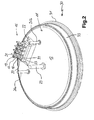
- Fig. 1 is a cover 11 shown according to the invention obliquely from below, which, as well as from the sectional drawing in Fig. 3 is clear, disc-like or plate-like is formed with a bottom 12 which is substantially flat, and a protruding outer edge 13.
- the cover member 11 is made of pressed vermiculite. Details of the pressing process such as pressing or pressing pressure, the expert knows for example from the DE 19522798 A1 ,
- the cover 11 has the electrical connections 15. These consist of four connection parts 17 with sockets 18, in which inserted connection lines are fixed by means of screws 19. To the center of the cover member 11 are terminal lugs 20 from the connection parts 17 from, according to which Fig. 3 Connecting wires 39 are guided to heating elements 37. From the other side are, as can be seen from the other figures, plug connection lugs 21 from. These represent an alternative connection option to the screw sockets 18 for connecting cables.
- the connecting parts 17 have fastening portions 24, which are guided down into an elevated terminal base 22 and are pressed therein, such as from Fig. 3 can be seen. This serves for stable attachment of the connecting parts 17 by means of the fastening portions 24 in the connection sockets 22.
- the terminal base 22 is made in one piece or integral with the other cover 11. It projects a good distance over the bottom 12 to make room for the electrical connections 15, so that they are easily accessible.
- the connection socket 22 has holes 23 for the connection wires 39, which pass completely through the cover part 11 and end close to the connection lugs 20 of the connection parts 17. This will be explained in more detail below. If the terminal socket were to be manufactured separately, a dividing line would run on the back of the cover 11. He would then, for example, be glued together with the electrical connections 15 contained therein.
- protruding anti-rotation bolts 26a and 26b are included in the cover 11 from the bottom 12. They are as well as the mounting portions 24 of the connecting parts 17 during pressing of the cover 11 is integrated therein and prevent the subsequent installation of the finished hotplate in a hob twisting.
- Fig. 2 the cover member 11 according to the invention is installed to a hotplate 30 according to the invention.
- a continuous hole 28 is included, in which a bolt 29 is used, such as Fig. 2 shows.
- the cover 11 is inserted into a hotplate body 31, as well as above all good Fig. 3 can be seen.
- the hotplate body 31 has a hotplate top 32 and a far downwardly projecting outer edge 33 which is tubular.
- the bottom 35 of the hotplate 30 is as usual educated. It has a central dome 36, in which the aforementioned screw 29 is screwed in after insertion of the cover 11 and the cover firmly on the bottom 35 of the hotplate body 31 holds.
- 35 heating elements 37 are arranged and potted on the bottom, as is also common in hotplates.
- heating elements 37 go from connecting wires 39, of which only one is shown. It extends through the hole 23 in the cover 11 and in the connection socket 22 through, is slightly above and is welded to the corresponding adjacent terminal lug 20 for electrical connection. These leads 39 must be threaded through the holes 23 when attaching the separately prepared cover 11 to the bottom 35 of the hotplate body 31, but this does not make too much trouble. Subsequently, by means of the screw bolt 29, the cover member 11 is mounted with the hotplate body 31 together to the hotplate 30.
- FIG. 4 An alternative embodiment of the cover 111 with basically similar structural design is in Fig. 4 shown in section.
- the hotplate body 131 of the hotplate 130 is formed as well as the one Fig. 3 , however, here the cover member 111 is not made separately with the electrical connections 115 and the anti-rotation pin 126, but pressed directly onto the bottom 135 of the hotplate body 131 or molded. However, in this case too, the connection parts 117 and the anti-rotation bolts 126 are formed and are then stably held therein.
- connection wires 139 for the heating elements 137 are guided in such a way that they can be welded to the terminal lugs 120 of the connecting parts 117 either after the pressing.
- connection wires 139 and connection lugs 120 are already welded in advance and then already pressed into the thermal insulation material of the cover 111 pressed.
- the connection parts 117 which are identical to those of Fig. 1 , Attachment sections 124 which extend far into the terminal socket 122 for stable attachment therein.
- the finished cooking plate 130 can be mounted in a hob.
- the thermal insulation material of the cover 111 extends directly to the bottom 135 of the hotplate body 131.
- the heating elements 137 are very well sealed or sealed and are therefore not susceptible to moisture and other harmful influences.
- the sectional view in Fig. 3 Namely, it can be seen that there is a clear distance between the cover 11 and the cooking plate bottom 135 here. However, this could also be less or the cover could also be made thicker, for example, for more stability.
Landscapes
- Baking, Grill, Roasting (AREA)
- Resistance Heating (AREA)
Applications Claiming Priority (1)
| Application Number | Priority Date | Filing Date | Title |
|---|---|---|---|
| DE200710038782 DE102007038782A1 (de) | 2007-08-06 | 2007-08-06 | Abdeckteil für die Unterseite einer Kochplatte und Herstellungsverfahren und Kochplatte mit einem solchen Abdeckteil und Herstellungsverfahren |
Publications (2)
| Publication Number | Publication Date |
|---|---|
| EP2023689A2 true EP2023689A2 (fr) | 2009-02-11 |
| EP2023689A3 EP2023689A3 (fr) | 2011-04-13 |
Family
ID=39865751
Family Applications (1)
| Application Number | Title | Priority Date | Filing Date |
|---|---|---|---|
| EP08013138A Withdrawn EP2023689A3 (fr) | 2007-08-06 | 2008-07-22 | Elément de recouvrement pour la partie inférieure d'une plaque de cuisson et procédé de fabrication et plaque de cuisson dotée d'un tel élément de recouvrement et procédé de fabrication |
Country Status (2)
| Country | Link |
|---|---|
| EP (1) | EP2023689A3 (fr) |
| DE (1) | DE102007038782A1 (fr) |
Cited By (1)
| Publication number | Priority date | Publication date | Assignee | Title |
|---|---|---|---|---|
| US12111048B2 (en) | 2021-01-11 | 2024-10-08 | Signify Holding, B.V. | Light emitting device |
Families Citing this family (1)
| Publication number | Priority date | Publication date | Assignee | Title |
|---|---|---|---|---|
| DE102013214499A1 (de) | 2013-07-24 | 2014-07-17 | E.G.O. Elektro-Gerätebau GmbH | Gehäusevorrichtung, Anordnung einer Gehäusevorrichtung und Verfahren zur Montage einer Gehäusevorrichtung |
Citations (2)
| Publication number | Priority date | Publication date | Assignee | Title |
|---|---|---|---|---|
| DE19522798A1 (de) | 1995-06-23 | 1997-01-02 | Ego Elektro Blanc & Fischer | Verfahren zur Herstellung eines Strahlungsheizkörpers und Strahlungsheizkörper |
| DE102007017456A1 (de) | 2007-04-04 | 2008-10-09 | E.G.O. Elektro-Gerätebau GmbH | Anschlussvorrichtung für eine Elektrokochplatte und Elektrokochplatte |
Family Cites Families (2)
| Publication number | Priority date | Publication date | Assignee | Title |
|---|---|---|---|---|
| GB437636A (en) * | 1934-06-14 | 1935-11-01 | British Thomson Houston Co Ltd | Improvements in and relating to electric heating plates |
| DE3527533A1 (de) * | 1985-08-01 | 1987-02-12 | Ego Elektro Blanc & Fischer | Elektrokochplatte |
-
2007
- 2007-08-06 DE DE200710038782 patent/DE102007038782A1/de not_active Withdrawn
-
2008
- 2008-07-22 EP EP08013138A patent/EP2023689A3/fr not_active Withdrawn
Patent Citations (2)
| Publication number | Priority date | Publication date | Assignee | Title |
|---|---|---|---|---|
| DE19522798A1 (de) | 1995-06-23 | 1997-01-02 | Ego Elektro Blanc & Fischer | Verfahren zur Herstellung eines Strahlungsheizkörpers und Strahlungsheizkörper |
| DE102007017456A1 (de) | 2007-04-04 | 2008-10-09 | E.G.O. Elektro-Gerätebau GmbH | Anschlussvorrichtung für eine Elektrokochplatte und Elektrokochplatte |
Cited By (1)
| Publication number | Priority date | Publication date | Assignee | Title |
|---|---|---|---|---|
| US12111048B2 (en) | 2021-01-11 | 2024-10-08 | Signify Holding, B.V. | Light emitting device |
Also Published As
| Publication number | Publication date |
|---|---|
| DE102007038782A1 (de) | 2009-02-19 |
| EP2023689A3 (fr) | 2011-04-13 |
Similar Documents
| Publication | Publication Date | Title |
|---|---|---|
| DE3629796C1 (en) | Electrical series terminal arrangement | |
| DE4036249A1 (de) | Aus einem metallischen werkstoff, wie stahlblech, bestehender kanal zur unterbringung von elektrischen installationseinrichtungen | |
| DE102011078333A1 (de) | Überspannungsableiter | |
| DE102008025428B4 (de) | Verfahren zur Herstellung einer elektrische Anschlusseinrichtung | |
| EP2940819A1 (fr) | Garniture d'extrémité de câble | |
| EP2023689A2 (fr) | Elément de recouvrement pour la partie inférieure d'une plaque de cuisson et procédé de fabrication et plaque de cuisson dotée d'un tel élément de recouvrement et procédé de fabrication | |
| EP1286046A2 (fr) | Support por un dispositif de préchauffage de l'eau | |
| EP2012395A2 (fr) | Connexion à fiche électrique dotée de pare-chocs et/ou becs d'entrée de câbles en matière élastique | |
| EP3716408A1 (fr) | Protection flexible contre les contacts pour un raccordement électrique | |
| DE102013005327A1 (de) | Überspannungsschutzanordnung mit scheibenförmigem Varistor | |
| EP3221935B1 (fr) | Dispositif de liaison électrique et procédé de production dudit dispositif de liaison électrique | |
| DE29716019U1 (de) | Kabel-Stecker-Durchführung für ein Gehäuse | |
| EP3292592B1 (fr) | Cosse de batterie et son procédé de fabrication | |
| DE3633854A1 (de) | Schraubklemme | |
| DE102015107050A1 (de) | Batterieklemme | |
| DE102010024341A1 (de) | Verbindungsvorrichtung und Verteilerschrank-Anordnung | |
| DE102008026316A1 (de) | Intumeszierendes elektrisches Installationsteil | |
| EP0279916B1 (fr) | Dispositif à bornes de connexion, en particulier pour des inductances ou des transformateurs | |
| DE202019005220U1 (de) | Elektrische Heizvorrichtung | |
| DE202018105221U1 (de) | Energieverteiler | |
| EP1703607A1 (fr) | Griffe d'ancrage pour la fixation d'une prise d'antenne | |
| DE202018006279U1 (de) | Leiter mit integrierter Leitersicherung | |
| DE102008048840A1 (de) | Überspannungsableiter mit Käfig-Design | |
| DE102016112637B3 (de) | Trennfunkenstrecke | |
| DE3129061A1 (de) | Elektrisches installationsgeraet |
Legal Events
| Date | Code | Title | Description |
|---|---|---|---|
| PUAI | Public reference made under article 153(3) epc to a published international application that has entered the european phase |
Free format text: ORIGINAL CODE: 0009012 |
|
| AK | Designated contracting states |
Kind code of ref document: A2 Designated state(s): AT BE BG CH CY CZ DE DK EE ES FI FR GB GR HR HU IE IS IT LI LT LU LV MC MT NL NO PL PT RO SE SI SK TR |
|
| AX | Request for extension of the european patent |
Extension state: AL BA MK RS |
|
| PUAL | Search report despatched |
Free format text: ORIGINAL CODE: 0009013 |
|
| AK | Designated contracting states |
Kind code of ref document: A3 Designated state(s): AT BE BG CH CY CZ DE DK EE ES FI FR GB GR HR HU IE IS IT LI LT LU LV MC MT NL NO PL PT RO SE SI SK TR |
|
| AX | Request for extension of the european patent |
Extension state: AL BA MK RS |
|
| AKY | No designation fees paid | ||
| REG | Reference to a national code |
Ref country code: DE Ref legal event code: R108 |
|
| REG | Reference to a national code |
Ref country code: DE Ref legal event code: R108 Effective date: 20111221 |
|
| STAA | Information on the status of an ep patent application or granted ep patent |
Free format text: STATUS: THE APPLICATION IS DEEMED TO BE WITHDRAWN |
|
| 18D | Application deemed to be withdrawn |
Effective date: 20111014 |