EP2023716B1 - Dispositif de capture d'insectes, d'araignées et d'autres petits animaux similaires - Google Patents
Dispositif de capture d'insectes, d'araignées et d'autres petits animaux similaires Download PDFInfo
- Publication number
- EP2023716B1 EP2023716B1 EP07720160A EP07720160A EP2023716B1 EP 2023716 B1 EP2023716 B1 EP 2023716B1 EP 07720160 A EP07720160 A EP 07720160A EP 07720160 A EP07720160 A EP 07720160A EP 2023716 B1 EP2023716 B1 EP 2023716B1
- Authority
- EP
- European Patent Office
- Prior art keywords
- suction tube
- piston
- housing
- spring
- situated
- Prior art date
- Legal status (The legal status is an assumption and is not a legal conclusion. Google has not performed a legal analysis and makes no representation as to the accuracy of the status listed.)
- Not-in-force
Links
Images
Classifications
-
- A—HUMAN NECESSITIES
- A01—AGRICULTURE; FORESTRY; ANIMAL HUSBANDRY; HUNTING; TRAPPING; FISHING
- A01M—CATCHING, TRAPPING OR SCARING OF ANIMALS; APPARATUS FOR THE DESTRUCTION OF NOXIOUS ANIMALS OR NOXIOUS PLANTS
- A01M3/00—Manual implements, other than sprayers or powder distributors, for catching or killing insects, e.g. butterfly nets
- A01M3/005—Manual suction tools for catching insects
Definitions
- the invention relates to a device for catching insects, spiders and other such small animals according to one part of claim 1.
- Another solution is provided by devices with an impulse aspirator and suction nozzle connected to it. It is based on the knowledge that z. B. a fly with the finger can usually approach to about 1 cm before flying away. A suction nozzle required for sucking a fly has about a cross-sectional dimensions of a finger or thumb, and one need only a short pulse-like sucking impulse to suck in at a short distance, the object.
- a device of this kind is from the DE 3225330A1 known.
- a hollow cylinder in which a piston and a clamping elements are arranged, preceded by a detachable fishing nipple, in which there is the catching space for the insects.
- the catching space is closed on the inlet side by a blocking element acting as a one-way valve, and on the outlet side by a strainer basket.
- the tensioning element forming coil spring which stores its energy by axial compression, is disposed between the front of the piston and the front end of the hollow cylinder.
- a tension member for the coil spring acting on the back of the piston plunger is provided, which is attached to the bottom of a clamping pot and out on the hollow cylinder.
- a hollow cylinder upstream is required by a strainer against this closed trap.
- the actuated by the coil spring piston which is guided only on the cylindrical piston surface in the hollow cylinder, can tilt relatively easily and thereby disturb the intake process.
- a further developed impulse suction disclosed the G 91 16 394.3, in which the resilient clamping elements between the back of the piston and the bottom part of the hollow cylinder are arranged.
- the piston is connected on the back with a guide rod for guiding the piston and for tensioning the elastic tensioning elements. This ensures that the guide rod connected to the piston ensures safe guidance of the piston.
- it serves as a tension member for the tension springs, by being provided with a tension lever.
- the disadvantage of this arrangement is the complex construction and the length of the pulse sucker, which results from the length of the suction tube, the length of the cylinder and the length of the handle with clamping lever.
- the present invention has for its object to overcome these disadvantages of known devices for catching insects, spiders and other such small animals.
- a spring-elastic element for example a compression spring, is arranged between the piston and the bottom part of the suction tube in a hollow cylinder.
- the suction pipe operatively connected to the piston via the resilient element is displaceable in the axial direction and movably held in a passage of the front cylinder wall.
- the piston has suction pipe side locking means, which are provided for locking in a arranged in the bottom part of the suction tube recording, and which are releasable via a triggering mechanism operable from the outside.
- the suction tube For actuation, that is, for tensioning the impulse suction, the suction tube is pushed into the cylinder and pressed against the pressure force of the resilient element in the direction of the cylinder base until the locking means of the piston in the holding device in the bottom part of the suction tube entered.
- trigger that is to catch an insect
- the suction pipe is pulled out of the cylinder and the piston connected to the suction tube via the resilient element pushed towards the front cylinder wall, so that the triggering device engages with the locking means and by pressing the trigger, the holding device unlocked.
- the suction pipe Due to the pressure force of the resilient element, on the one hand, the suction pipe is now pushed further out of the cylinder until the bottom part of the suction pipe is present on the inside of the front cylinder wall, and on the other hand, the piston is pressed in the direction of the cylinder base. This creates a negative pressure in the cylinder space between the piston and the bottom part of the intake manifold, whereby air is sucked through the intake manifold. This air stream sucks an insect located in front of the suction pipe into the catching space arranged in the front region of the suction pipe.
- the suction pipe still approaches the object to be caught when the catching process is triggered, which gives increased safety in catching, and secondly, the overall size of the device can be kept small since the suction pipe can be pushed into the cylinder when not in use.
- Another advantage is that the impulse aspirator can only be triggered when the suction pipe is positioned in the device accordingly, so that the triggering device can be unlocked, which has an increased safety in dealing with the Impulse sucker result.
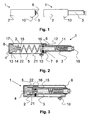
- FIG. 1 For example, an embodiment of the safety device 1 according to the invention with a cylinder-like housing part 2 and a suction tube 3 is shown.
- the suction tube 3 is displaceable in the axial direction and movably guided in a passage in the front wall 6 of the cylinder-like housing part 2.
- the suction pipe 3 In the left picture of the FIG. 1 the suction pipe 3 is located in the housing part 2.
- the right figure shows the safety gear 1 with fully extended suction pipe. 3
- FIG. 2 shows a cross section through the longitudinal axis of the safety gear 1.
- a piston 4 is arranged, which is operatively connected via a resilient element, such as a compression spring 5 with the bottom 7 of the suction tube 3.
- the relaxed spring 5 pushes the piston 4 and the suction tube 3 aurder, so that the piston 4 on the rear housing wall 8 and the bottom 7 of the suction tube 3 rests against the front housing wall 6.
- the suction tube 3 is guided in the passage 9 of the front housing wall 6.
- the bottom 7 of the suction tube 3 has an inner diameter which corresponds approximately to the inner diameter of the housing 2, so that the suction tube 3 is displaceable in the axial direction, without tilting.
- a longitudinally extending web 11 is arranged, which engages in a recess 12 in the passage 9 of the front housing wall 6.
- the punch-shaped piston 4 has a diameter which corresponds approximately to the inner diameter of the cylindrical piston housing 2.
- a seated in an annular groove 14 in the piston 4 seal 13 is characterized sealingly against the inner wall of the piston housing 2.
- the piston 4 is graduated suction pipe side and ends in a nipple 15 which forms a locking means which is provided for locking in a arranged in the bottom part 7 of the suction tube 3 holding device with a lock 16.
- the holding device is formed by a slide 26 which is guided in a run perpendicular to the longitudinal axis slot 25 and, spring-loaded.
- the slider 26 has a hole for receiving the nipple 15 and is intended to engage in the groove 22 of the nipple 15.
- the first step in the piston 4 forms a shoulder 17, which serves to receive the compression spring 5.
- a removable catcher 18 is arranged for receiving the insects to be caught.
- a shutter designed as a push button 10 can be seen. In the illustrated position, which shows the state after a capture process, the suction pipe 3 is maximally extended and the piston 4 is located at the rear end of the piston housing second
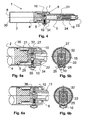
- FIG. 3 is a cross section through the longitudinal axis of the safety gear 1 with tensioned compression spring 5 is shown.
- the suction tube 3 is pushed against the spring force of the compression spring 5 in the housing 2.
- the latch 16 arranged in the holding device snaps into an annular groove 22 in the nipple 15.
- the piston 4 under the tension of the compression spring 5 is held together with the suction tube 3.
- the suction tube 3 is located almost entirely in the housing 2. Only the foremost part of the suction tube 3 protrudes from the front cylinder wall 6.
- the lock 16 Since in this position, the lock 16 is not accessible from the outside, it can not be solved.
- the safety gear 1 is indeed tense but still secured. If the intake manifold 3 is pulled axially out of the housing 2, then the piston 4 connected and locked to the intake manifold 3 via the holding device 16 likewise moves in the direction of the front cylinder wall 6. The capture process can then be triggered when the piston 4 engages the bottom 7 of the suction tube 3 in the housing 2 are positioned so that the lock 16 is actuated by the trigger.
- a stop 34 is provided on the inside of the housing wall in the region of the trigger 10, to which the slider 26 is present as soon as the suction tube 3 is fully extended. By pressing the trigger 10, the holding device is unlocked and triggered the catching process.
- FIG. 4 shows the safety device in a cross section through the longitudinal axis with a tensioned compression spring in the locked release position.
- the trigger 10 and the stop 34 are arranged on the housing 2 so that the bottom 7 of the suction tube 3 does not touch the front cylinder wall 6 in this position. Now, if the trigger 10 is pressed for a catch, the lock 16 is released and the suction tube 3 speeds forward on the one hand until the bottom 7 of the suction tube 3 is present on the inside of the front cylinder wall 6, and on the other hand, the piston 4 speeds towards the rear housing wall 8.
- the wires are funnel-shaped inward and directed against the longitudinal axis and form a kind of barbs, so that an insect sucked in can not escape from the catcher.
- a sieve 24 is provided, so that the insect is not sucked into the housing.
- the arranged in the front region of the suction pipe 3 catcher 18 is shock-damped with a support spring 31. This means that the catcher 18 can be pressed against the spring force of the spring 31 in the intake manifold 3. If the catch container 18 is unloaded again in the axial direction, it is pushed back by the intercepting spring into its original position.
- This shock absorption has the task of intercepting a shock through the suction tube 3 to an object or object, if the safety gear 1 was held with the suction tube 3 when triggering a fishing process too close to a solid object. This can be used to prevent injuries to persons or damage to objects.
- FIG. 5a shows a partial view of a cross section through the longitudinal axis of the safety gear 1 in the region of the holding device or the trigger 10 in the locked position.
- the nipple 15 is located in the piston-side opening 21 of the suction pipe 3.
- the edge of the opening 21 has a funnel-shaped chamfer.
- the nipple 15 is tapered in a truncated cone at its front end. This ensures that when inserting the nipple 15 in the opening 21 of the nipple 15 automatically centered in the opening 21 of the suction tube 3.
- the bottom 7 of the suction tube 3 has a perpendicular to the longitudinal axis slot 25, in which a slider 26 is inserted.
- FIG. 5b is a cross section perpendicular to the longitudinal axis of the safety gear in the region of the holding device in the locked position represented, in which the details of the holding device can be seen.
- a blind hole 32 is provided, in which a compression spring 27 is inserted. This spring 27 presses the slider against the inner wall of the housing 2.
- the hole 33 in the slider 26 is decentered with respect to the longitudinal axis of the piston 4 and the suction tube.
- FIGS. 5a and 5b show the same partial views as the FIGS. 5a and 5b , with the difference that the spring-loaded with spring 35 push button 10 is pressed, whereby the pin 29 pushes the slider 26 against the spring pressure of the spring 27 from the groove 22 in the nipple 15.
- the holding device 16 is unlocked and the piston 4 is no longer held together with the suction tube 3.
- the suction pipe 3 and the piston 4 are pressed in opposite directions from each other.
- the air channel 36 connects the suction tube 3 with the interior of the piston housing 2 and allows that during the capture process immediately after triggering already air from the suction tube 3 can be sucked, although the nipple 15 still covers part of the opening 21.
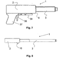
- FIG. 7 shows a further embodiment of the inventive safety gear 1.
- a pistol-like handle 37 is arranged with a trigger 38.
- the trigger 10 is actuated via a rocker arm 39.
- FIG. 8 shown expedient development of the invention is that the suction tube 3 is formed in the form of a telescopic tube 40.
- a device equipped with such a telescopic tube 40 locations within a room can be achieved, which are usually not accessible without aids, such. As the corners between the ceiling and the walls of living spaces.
- the device according to the invention is thus much simpler and smaller in its construction and overall safe in its application and mode of operation in comparison with known devices.
Landscapes
- Life Sciences & Earth Sciences (AREA)
- Pest Control & Pesticides (AREA)
- Engineering & Computer Science (AREA)
- Insects & Arthropods (AREA)
- Wood Science & Technology (AREA)
- Zoology (AREA)
- Environmental Sciences (AREA)
- Catching Or Destruction (AREA)
- Micro-Organisms Or Cultivation Processes Thereof (AREA)
Claims (10)
- Dispositif pour capturer des insectes, araignées et autres petits animaux similaires au moyen d'un aspirateur à impulsions (1) comprenant une partie de boîtier cylindrique (2), un piston (4), un tube d'aspiration (3) et un élément élastique à la manière d'un ressort (5), dans lequel l'élément élastique à la manière d'un ressort (5) est formé par un ressort de compression qui est disposé entre le piston (4) et le tube d'aspiration (3) à l'intérieur de la partie de boîtier cylindrique (2), et le tube d'aspiration (3) en liaison active avec le piston (4) par l'intermédiaire du ressort de compression (5) est guidé de façon mobile dans le sens axial dans une ouverture (9) dans la paroi antérieure (6) de la partie de boîtier cylindrique (2), et le piston (4) présente du côté du tube d'aspiration des moyens d'engagement (15, 22) destinés à s'engager dans un dispositif de maintien prévu à cette fin dans la partie de fond (7) du tube d'aspiration (3) avec un verrouillage (16), lesquels peuvent être déverrouillés à l'aide d'un déclencheur (10) pouvant être actionné de l'extérieur.
- Dispositif selon la revendication 1, caractérisé en ce que les moyens d'engagement sont formés par un téton (15) avec une gorge annulaire (22) disposé du côté du tube d'aspiration sur le piston (4).
- Dispositif selon la revendication 2, caractérisé en ce que le dispositif de maintien (16) comprend une coulisse (26) contrainte par un ressort qui est guidée dans une fente (25) perpendiculaire à l'axe longitudinal du dispositif et qui présente un trou (33) destiné à recevoir le téton (15), en ce qu'il est en outre prévu dans le fond de la fente (25) un trou borgne (32) avec un ressort de compression (27) qui pousse la coulisse (26) contre la paroi intérieure du boîtier (2).
- Dispositif selon la revendication 2, caractérisé en ce que le téton (15) présente un alésage longitudinal orienté dans le sens axial, qui débouche dans un alésage transversal qui lui est perpendiculaire, de telle sorte que ces deux alésages forment un canal pour l'air (36).
- Dispositif selon l'une des revendications précédentes, caractérisé en ce qu'il est prévu sur la face supérieure du tube d'aspiration (3) une barrette (11) orientée dans le sens longitudinal qui se met en prise dans un creux (12) dans l'ouverture (9) de la paroi antérieure du boîtier (6).
- Dispositif selon l'une des revendications précédentes, caractérisé en ce qu'il est prévu dans la partie d'extrémité antérieure du tube d'aspiration (3) un réservoir de capture (18) amovible avec un couvercle en forme de nasse (23) à son embouchure.
- Dispositif selon la revendication 6, caractérisé en ce que le réservoir de capture (18) est amorti contre les chocs dans le sens longitudinal au moyen d'un ressort d'absorption (31).
- Dispositif selon l'une des revendications précédentes, caractérisé en ce qu'il est prévu sur le boîtier (2) du dispositif de capture (1) une poignée en forme de pistolet (37) avec un levier de traction (38) et un levier basculant (39) pour l'actionnement du déclencheur (10).
- Dispositif selon l'une des revendications précédentes, caractérisé en ce que le tube d'aspiration (3) est conformé comme un tube télescopique (40).
- Dispositif selon l'une des revendications précédentes, caractérisé en ce que le déclencheur (10) est disposé sur le boîtier (2) de telle façon que le fond (7) du tube d'aspiration (3) est mobile en direction de la paroi antérieure du boîtier lors du déclenchement d'une opération de capture.
Applications Claiming Priority (2)
| Application Number | Priority Date | Filing Date | Title |
|---|---|---|---|
| CH9272006 | 2006-06-08 | ||
| PCT/CH2007/000263 WO2007140636A1 (fr) | 2006-06-08 | 2007-05-24 | Dispositif de capture d'insectes, d'araignées et d'autres petits animaux similaires |
Publications (2)
| Publication Number | Publication Date |
|---|---|
| EP2023716A1 EP2023716A1 (fr) | 2009-02-18 |
| EP2023716B1 true EP2023716B1 (fr) | 2009-08-26 |
Family
ID=38519665
Family Applications (1)
| Application Number | Title | Priority Date | Filing Date |
|---|---|---|---|
| EP07720160A Not-in-force EP2023716B1 (fr) | 2006-06-08 | 2007-05-24 | Dispositif de capture d'insectes, d'araignées et d'autres petits animaux similaires |
Country Status (7)
| Country | Link |
|---|---|
| US (1) | US8074395B2 (fr) |
| EP (1) | EP2023716B1 (fr) |
| CN (1) | CN101466261B (fr) |
| AT (1) | ATE440496T1 (fr) |
| DE (1) | DE502007001418D1 (fr) |
| ES (1) | ES2331666T3 (fr) |
| WO (1) | WO2007140636A1 (fr) |
Families Citing this family (19)
| Publication number | Priority date | Publication date | Assignee | Title |
|---|---|---|---|---|
| US8276313B2 (en) | 2003-09-17 | 2012-10-02 | Gerd Reime | Method and apparatus for trapping insects |
| ES2302636B1 (es) * | 2006-11-30 | 2009-05-21 | Consejo Superior Investig. Cienficas | Equipo para la manipulacion aseptica de animales de laboratorio. |
| US20120311921A1 (en) * | 2009-08-20 | 2012-12-13 | Ogilvie John W | Kinetic non-adhesive pest control amusement devices and methods |
| US20140047759A1 (en) * | 2012-08-15 | 2014-02-20 | Charles Almy | Bug catching device |
| CN103287779B (zh) * | 2013-06-04 | 2016-04-13 | 无锡明珠钢球有限公司 | 简易钢球拾捡器 |
| CN103918626B (zh) * | 2014-04-14 | 2016-09-14 | 慈溪市宝日电器有限公司 | 一种苍蝇或蚊虫捡拾装置 |
| CN103891693B (zh) * | 2014-04-14 | 2016-03-30 | 慈溪市芮奇塑胶有限公司 | 一种吸管式苍蝇或蚊虫捡拾装置 |
| CN103931586B (zh) * | 2014-04-14 | 2016-08-17 | 慈溪市桥头京姬电子元件厂 | 一种抽吸式苍蝇或蚊虫捡拾装置 |
| CN104488842A (zh) * | 2014-12-24 | 2015-04-08 | 吕皓 | 一种负压式灭蚊器 |
| US10881094B2 (en) | 2017-10-11 | 2021-01-05 | Tony Guo | Insect vacuum and trap attachment systems |
| CN108782502B (zh) * | 2018-05-22 | 2021-06-08 | 曾钰翔 | 一种昆虫捕捉器 |
| CN109497016A (zh) * | 2018-12-20 | 2019-03-22 | 贵州师范大学 | 一种多功能吸虫管 |
| CN110250128B (zh) * | 2019-06-26 | 2024-04-26 | 建德市艾格电器有限公司 | 一种吸虫装置 |
| US11363809B2 (en) * | 2020-01-22 | 2022-06-21 | Paul Gangarosa | Insect vacuum device |
| CN111493040B (zh) * | 2020-06-15 | 2021-09-07 | 浙江陶氏集团黄岩模具二厂有限公司 | 一种环保灭蚊装置 |
| CN112388372B (zh) * | 2020-09-23 | 2021-12-28 | 宁波高新区利威科技有限公司 | 一种夹紧卸料机构 |
| US12310351B1 (en) | 2023-11-10 | 2025-05-27 | Scott Lucas | Insect collection device |
| CN118140894A (zh) * | 2024-03-04 | 2024-06-07 | 枣庄市市中区乡村振兴服务中心 | 一种番茄作物防虫害用幼虫样本采集装置 |
| CN119969357A (zh) * | 2025-04-11 | 2025-05-13 | 长沙矿冶研究院有限责任公司 | 浮游动物诱捕监测装置及工作方法 |
Family Cites Families (12)
| Publication number | Priority date | Publication date | Assignee | Title |
|---|---|---|---|---|
| DE270634C (fr) * | 1912-02-26 | |||
| US1141039A (en) * | 1915-04-20 | 1915-05-25 | Robert Hanham Cox | Fly-trap. |
| US3965608A (en) * | 1972-07-10 | 1976-06-29 | Mark Schuman | Manually operated suction device for capturing small objects |
| DE3225330A1 (de) | 1982-07-07 | 1984-01-12 | Jochen Reinhold 5910 Kreuztal Zoz | Geraet zum absaugen einzelner objekte, insbesondere insekten, fliegen, wespen, u.dgl. |
| US4733495A (en) * | 1987-05-21 | 1988-03-29 | James Winnicki | Flying insect exterminator |
| DE9116394U1 (de) | 1991-05-31 | 1992-09-03 | Arned Gesellschaft für die Entwicklung von Produktneuheiten mbH, 5180 Eschweiler | Vorrichtung zum Lebendfangen von Insekten |
| DE4327150A1 (de) * | 1993-08-12 | 1995-02-16 | Heinz Peter Brandstetter | Verfahren und Vorrichtung zum Fangen von Insekten |
| US5367821A (en) * | 1993-10-18 | 1994-11-29 | Ott; Gary D. | Suction insect trap apparatus |
| US7014622B1 (en) * | 1999-02-18 | 2006-03-21 | Medsafe Technologies, Llc | Interchangeable needle safety syringe |
| JP2003092963A (ja) * | 2001-09-25 | 2003-04-02 | Ryoichi Morimoto | 吸引式捕虫器 |
| CN2722637Y (zh) * | 2004-04-15 | 2005-09-07 | 陶章菊 | 杀蝇枪 |
| US20050246945A1 (en) * | 2004-05-10 | 2005-11-10 | David Evink | Insect capturing device |
-
2007
- 2007-05-24 AT AT07720160T patent/ATE440496T1/de active
- 2007-05-24 EP EP07720160A patent/EP2023716B1/fr not_active Not-in-force
- 2007-05-24 CN CN2007800211617A patent/CN101466261B/zh not_active Expired - Fee Related
- 2007-05-24 ES ES07720160T patent/ES2331666T3/es active Active
- 2007-05-24 WO PCT/CH2007/000263 patent/WO2007140636A1/fr not_active Ceased
- 2007-05-24 DE DE502007001418T patent/DE502007001418D1/de active Active
- 2007-05-24 US US12/303,478 patent/US8074395B2/en not_active Expired - Fee Related
Also Published As
| Publication number | Publication date |
|---|---|
| ES2331666T3 (es) | 2010-01-12 |
| US20090313884A1 (en) | 2009-12-24 |
| WO2007140636A1 (fr) | 2007-12-13 |
| EP2023716A1 (fr) | 2009-02-18 |
| ATE440496T1 (de) | 2009-09-15 |
| DE502007001418D1 (de) | 2009-10-08 |
| CN101466261B (zh) | 2010-12-22 |
| HK1130156A1 (en) | 2009-12-24 |
| CN101466261A (zh) | 2009-06-24 |
| US8074395B2 (en) | 2011-12-13 |
Similar Documents
| Publication | Publication Date | Title |
|---|---|---|
| EP2023716B1 (fr) | Dispositif de capture d'insectes, d'araignées et d'autres petits animaux similaires | |
| EP2575587B1 (fr) | Aspirateur avec nettoyage de filtre par contre-courant | |
| DE2549477B2 (de) | Pipettiervorrichtung | |
| DE2903667A1 (de) | Pfeilabschiessvorrichtung und pfeil | |
| WO1984000280A1 (fr) | Appareil pour aspirer des objets isoles, par exemple des insectes, des mouches, des guepes, etc. | |
| DE4327150A1 (de) | Verfahren und Vorrichtung zum Fangen von Insekten | |
| DE102004009436A1 (de) | Zerstäuber | |
| EP2866632B1 (fr) | Combinaison composée d'un mini-aspirateur et d'un bâti d'aspirateur-balai, ainsi que mini-aspirateur et bâti d'aspirateur-balai | |
| DE2106982C2 (de) | Entlötvorrichtung | |
| DE4112266C1 (en) | Insect exhauster with piston in pump cylinder - has suction pipe with valve flap, opening in blow-out sense on air expelling from pump cylinder | |
| DE102011113859B3 (de) | Schlag- und Fangvorrichtung für Insekten und Ungeziefer | |
| EP0510472A1 (fr) | Collecteur pour les excréments d'animaux | |
| DE940436C (de) | Verfahren und pistolenartige Vorrichtung zur Vertilgung von Fliegen od. dgl. | |
| DE102022000628B4 (de) | Spinnen-Fanggerät | |
| WO2003061375A1 (fr) | Dispositif de capture pour petits animaux | |
| DE202017107648U1 (de) | Saughalter zum Vakuumsaugen | |
| DE202004001323U1 (de) | Insektenfalle | |
| DE19946707C2 (de) | Absaugvorrichtung zum Absaugen von flüssigen Überständen aus offenen Behältnissen | |
| DE2808785A1 (de) | Vorrichtung zum reinigen von teichen u.dgl. | |
| DE69913123T2 (de) | Insektenfangvorrichtung | |
| DE8219398U1 (de) | Geraet zum absaugen einzelner objekte, beispielsweise insekten, fliegen, wespen u. dgl. | |
| DE4322460A1 (de) | Insektenfangschachtel als Haushaltsgerät | |
| DE8603058U1 (de) | Vorrichtung zum Einfangen und Vernichten von schädlichen Insekten | |
| DE9116394U1 (de) | Vorrichtung zum Lebendfangen von Insekten | |
| DE20214815U1 (de) | Manuelles Fanggerät |
Legal Events
| Date | Code | Title | Description |
|---|---|---|---|
| PUAI | Public reference made under article 153(3) epc to a published international application that has entered the european phase |
Free format text: ORIGINAL CODE: 0009012 |
|
| 17P | Request for examination filed |
Effective date: 20081127 |
|
| AK | Designated contracting states |
Kind code of ref document: A1 Designated state(s): AT BE BG CH CY CZ DE DK EE ES FI FR GB GR HU IE IS IT LI LT LU LV MC MT NL PL PT RO SE SI SK TR |
|
| AX | Request for extension of the european patent |
Extension state: AL BA HR MK RS |
|
| GRAP | Despatch of communication of intention to grant a patent |
Free format text: ORIGINAL CODE: EPIDOSNIGR1 |
|
| GRAS | Grant fee paid |
Free format text: ORIGINAL CODE: EPIDOSNIGR3 |
|
| GRAA | (expected) grant |
Free format text: ORIGINAL CODE: 0009210 |
|
| AK | Designated contracting states |
Kind code of ref document: B1 Designated state(s): AT BE BG CH CY CZ DE DK EE ES FI FR GB GR HU IE IS IT LI LT LU LV MC MT NL PL PT RO SE SI SK TR |
|
| REG | Reference to a national code |
Ref country code: GB Ref legal event code: FG4D Free format text: NOT ENGLISH |
|
| REG | Reference to a national code |
Ref country code: CH Ref legal event code: EP |
|
| REG | Reference to a national code |
Ref country code: CH Ref legal event code: NV Representative=s name: SPIERENBURG & PARTNER AG, PATENT- UND MARKENANWAEL Ref country code: IE Ref legal event code: FG4D Free format text: LANGUAGE OF EP DOCUMENT: GERMAN |
|
| REF | Corresponds to: |
Ref document number: 502007001418 Country of ref document: DE Date of ref document: 20091008 Kind code of ref document: P |
|
| REG | Reference to a national code |
Ref country code: ES Ref legal event code: FG2A Ref document number: 2331666 Country of ref document: ES Kind code of ref document: T3 |
|
| LTIE | Lt: invalidation of european patent or patent extension |
Effective date: 20090826 |
|
| PG25 | Lapsed in a contracting state [announced via postgrant information from national office to epo] |
Ref country code: SE Free format text: LAPSE BECAUSE OF FAILURE TO SUBMIT A TRANSLATION OF THE DESCRIPTION OR TO PAY THE FEE WITHIN THE PRESCRIBED TIME-LIMIT Effective date: 20090826 Ref country code: IS Free format text: LAPSE BECAUSE OF FAILURE TO SUBMIT A TRANSLATION OF THE DESCRIPTION OR TO PAY THE FEE WITHIN THE PRESCRIBED TIME-LIMIT Effective date: 20091226 Ref country code: LT Free format text: LAPSE BECAUSE OF FAILURE TO SUBMIT A TRANSLATION OF THE DESCRIPTION OR TO PAY THE FEE WITHIN THE PRESCRIBED TIME-LIMIT Effective date: 20090826 Ref country code: FI Free format text: LAPSE BECAUSE OF FAILURE TO SUBMIT A TRANSLATION OF THE DESCRIPTION OR TO PAY THE FEE WITHIN THE PRESCRIBED TIME-LIMIT Effective date: 20090826 |
|
| NLV1 | Nl: lapsed or annulled due to failure to fulfill the requirements of art. 29p and 29m of the patents act | ||
| PG25 | Lapsed in a contracting state [announced via postgrant information from national office to epo] |
Ref country code: PL Free format text: LAPSE BECAUSE OF FAILURE TO SUBMIT A TRANSLATION OF THE DESCRIPTION OR TO PAY THE FEE WITHIN THE PRESCRIBED TIME-LIMIT Effective date: 20090826 Ref country code: SI Free format text: LAPSE BECAUSE OF FAILURE TO SUBMIT A TRANSLATION OF THE DESCRIPTION OR TO PAY THE FEE WITHIN THE PRESCRIBED TIME-LIMIT Effective date: 20090826 Ref country code: LV Free format text: LAPSE BECAUSE OF FAILURE TO SUBMIT A TRANSLATION OF THE DESCRIPTION OR TO PAY THE FEE WITHIN THE PRESCRIBED TIME-LIMIT Effective date: 20090826 Ref country code: NL Free format text: LAPSE BECAUSE OF FAILURE TO SUBMIT A TRANSLATION OF THE DESCRIPTION OR TO PAY THE FEE WITHIN THE PRESCRIBED TIME-LIMIT Effective date: 20090826 |
|
| PG25 | Lapsed in a contracting state [announced via postgrant information from national office to epo] |
Ref country code: CY Free format text: LAPSE BECAUSE OF FAILURE TO SUBMIT A TRANSLATION OF THE DESCRIPTION OR TO PAY THE FEE WITHIN THE PRESCRIBED TIME-LIMIT Effective date: 20090826 Ref country code: PT Free format text: LAPSE BECAUSE OF FAILURE TO SUBMIT A TRANSLATION OF THE DESCRIPTION OR TO PAY THE FEE WITHIN THE PRESCRIBED TIME-LIMIT Effective date: 20091228 Ref country code: BG Free format text: LAPSE BECAUSE OF FAILURE TO SUBMIT A TRANSLATION OF THE DESCRIPTION OR TO PAY THE FEE WITHIN THE PRESCRIBED TIME-LIMIT Effective date: 20091126 |
|
| REG | Reference to a national code |
Ref country code: IE Ref legal event code: FD4D |
|
| PG25 | Lapsed in a contracting state [announced via postgrant information from national office to epo] |
Ref country code: CZ Free format text: LAPSE BECAUSE OF FAILURE TO SUBMIT A TRANSLATION OF THE DESCRIPTION OR TO PAY THE FEE WITHIN THE PRESCRIBED TIME-LIMIT Effective date: 20090826 Ref country code: DK Free format text: LAPSE BECAUSE OF FAILURE TO SUBMIT A TRANSLATION OF THE DESCRIPTION OR TO PAY THE FEE WITHIN THE PRESCRIBED TIME-LIMIT Effective date: 20090826 Ref country code: IE Free format text: LAPSE BECAUSE OF FAILURE TO SUBMIT A TRANSLATION OF THE DESCRIPTION OR TO PAY THE FEE WITHIN THE PRESCRIBED TIME-LIMIT Effective date: 20090826 Ref country code: EE Free format text: LAPSE BECAUSE OF FAILURE TO SUBMIT A TRANSLATION OF THE DESCRIPTION OR TO PAY THE FEE WITHIN THE PRESCRIBED TIME-LIMIT Effective date: 20090826 Ref country code: RO Free format text: LAPSE BECAUSE OF FAILURE TO SUBMIT A TRANSLATION OF THE DESCRIPTION OR TO PAY THE FEE WITHIN THE PRESCRIBED TIME-LIMIT Effective date: 20090826 |
|
| PG25 | Lapsed in a contracting state [announced via postgrant information from national office to epo] |
Ref country code: SK Free format text: LAPSE BECAUSE OF FAILURE TO SUBMIT A TRANSLATION OF THE DESCRIPTION OR TO PAY THE FEE WITHIN THE PRESCRIBED TIME-LIMIT Effective date: 20090826 |
|
| PLBE | No opposition filed within time limit |
Free format text: ORIGINAL CODE: 0009261 |
|
| STAA | Information on the status of an ep patent application or granted ep patent |
Free format text: STATUS: NO OPPOSITION FILED WITHIN TIME LIMIT |
|
| 26N | No opposition filed |
Effective date: 20100527 |
|
| PG25 | Lapsed in a contracting state [announced via postgrant information from national office to epo] |
Ref country code: GR Free format text: LAPSE BECAUSE OF FAILURE TO SUBMIT A TRANSLATION OF THE DESCRIPTION OR TO PAY THE FEE WITHIN THE PRESCRIBED TIME-LIMIT Effective date: 20091127 |
|
| BERE | Be: lapsed |
Owner name: JANCIC, SILVIN M. Effective date: 20100531 |
|
| PG25 | Lapsed in a contracting state [announced via postgrant information from national office to epo] |
Ref country code: MC Free format text: LAPSE BECAUSE OF NON-PAYMENT OF DUE FEES Effective date: 20100531 |
|
| PG25 | Lapsed in a contracting state [announced via postgrant information from national office to epo] |
Ref country code: BE Free format text: LAPSE BECAUSE OF NON-PAYMENT OF DUE FEES Effective date: 20100531 Ref country code: IT Free format text: LAPSE BECAUSE OF NON-PAYMENT OF DUE FEES Effective date: 20100524 |
|
| PG25 | Lapsed in a contracting state [announced via postgrant information from national office to epo] |
Ref country code: MT Free format text: LAPSE BECAUSE OF FAILURE TO SUBMIT A TRANSLATION OF THE DESCRIPTION OR TO PAY THE FEE WITHIN THE PRESCRIBED TIME-LIMIT Effective date: 20090826 |
|
| PGFP | Annual fee paid to national office [announced via postgrant information from national office to epo] |
Ref country code: ES Payment date: 20110518 Year of fee payment: 5 |
|
| PG25 | Lapsed in a contracting state [announced via postgrant information from national office to epo] |
Ref country code: HU Free format text: LAPSE BECAUSE OF FAILURE TO SUBMIT A TRANSLATION OF THE DESCRIPTION OR TO PAY THE FEE WITHIN THE PRESCRIBED TIME-LIMIT Effective date: 20100227 Ref country code: LU Free format text: LAPSE BECAUSE OF NON-PAYMENT OF DUE FEES Effective date: 20100524 |
|
| PG25 | Lapsed in a contracting state [announced via postgrant information from national office to epo] |
Ref country code: TR Free format text: LAPSE BECAUSE OF FAILURE TO SUBMIT A TRANSLATION OF THE DESCRIPTION OR TO PAY THE FEE WITHIN THE PRESCRIBED TIME-LIMIT Effective date: 20090826 |
|
| REG | Reference to a national code |
Ref country code: AT Ref legal event code: MM01 Ref document number: 440496 Country of ref document: AT Kind code of ref document: T Effective date: 20120524 |
|
| PG25 | Lapsed in a contracting state [announced via postgrant information from national office to epo] |
Ref country code: AT Free format text: LAPSE BECAUSE OF NON-PAYMENT OF DUE FEES Effective date: 20120524 |
|
| REG | Reference to a national code |
Ref country code: ES Ref legal event code: FD2A Effective date: 20131021 |
|
| PG25 | Lapsed in a contracting state [announced via postgrant information from national office to epo] |
Ref country code: ES Free format text: LAPSE BECAUSE OF NON-PAYMENT OF DUE FEES Effective date: 20120525 |
|
| REG | Reference to a national code |
Ref country code: FR Ref legal event code: PLFP Year of fee payment: 10 |
|
| REG | Reference to a national code |
Ref country code: CH Ref legal event code: PCOW Free format text: NEW ADDRESS: ALTE BAHNHOFSTRASSE 5, 5612 VILLMERGEN (CH) |
|
| REG | Reference to a national code |
Ref country code: FR Ref legal event code: PLFP Year of fee payment: 11 |
|
| REG | Reference to a national code |
Ref country code: FR Ref legal event code: PLFP Year of fee payment: 12 |
|
| PGFP | Annual fee paid to national office [announced via postgrant information from national office to epo] |
Ref country code: CH Payment date: 20200407 Year of fee payment: 14 Ref country code: FR Payment date: 20200523 Year of fee payment: 14 Ref country code: DE Payment date: 20200526 Year of fee payment: 14 |
|
| PGFP | Annual fee paid to national office [announced via postgrant information from national office to epo] |
Ref country code: GB Payment date: 20200528 Year of fee payment: 14 Ref country code: IT Payment date: 20200529 Year of fee payment: 14 |
|
| REG | Reference to a national code |
Ref country code: DE Ref legal event code: R119 Ref document number: 502007001418 Country of ref document: DE |
|
| REG | Reference to a national code |
Ref country code: CH Ref legal event code: PL |
|
| GBPC | Gb: european patent ceased through non-payment of renewal fee |
Effective date: 20210524 |
|
| PG25 | Lapsed in a contracting state [announced via postgrant information from national office to epo] |
Ref country code: CH Free format text: LAPSE BECAUSE OF NON-PAYMENT OF DUE FEES Effective date: 20210531 Ref country code: LI Free format text: LAPSE BECAUSE OF NON-PAYMENT OF DUE FEES Effective date: 20210531 |
|
| PG25 | Lapsed in a contracting state [announced via postgrant information from national office to epo] |
Ref country code: GB Free format text: LAPSE BECAUSE OF NON-PAYMENT OF DUE FEES Effective date: 20210524 Ref country code: DE Free format text: LAPSE BECAUSE OF NON-PAYMENT OF DUE FEES Effective date: 20211201 |
|
| PG25 | Lapsed in a contracting state [announced via postgrant information from national office to epo] |
Ref country code: FR Free format text: LAPSE BECAUSE OF NON-PAYMENT OF DUE FEES Effective date: 20210531 |
|
| PG25 | Lapsed in a contracting state [announced via postgrant information from national office to epo] |
Ref country code: IT Free format text: LAPSE BECAUSE OF NON-PAYMENT OF DUE FEES Effective date: 20210531 |