EP2023820B1 - Biopsiesystem mit integrierter ultraschallabbildung - Google Patents
Biopsiesystem mit integrierter ultraschallabbildung Download PDFInfo
- Publication number
- EP2023820B1 EP2023820B1 EP07795749.6A EP07795749A EP2023820B1 EP 2023820 B1 EP2023820 B1 EP 2023820B1 EP 07795749 A EP07795749 A EP 07795749A EP 2023820 B1 EP2023820 B1 EP 2023820B1
- Authority
- EP
- European Patent Office
- Prior art keywords
- tissue removal
- control module
- biopsy
- ultrasound
- probe
- Prior art date
- Legal status (The legal status is an assumption and is not a legal conclusion. Google has not performed a legal analysis and makes no representation as to the accuracy of the status listed.)
- Not-in-force
Links
- 238000001574 biopsy Methods 0.000 title claims description 51
- 238000003384 imaging method Methods 0.000 title claims description 45
- 239000000523 sample Substances 0.000 claims description 46
- 238000002604 ultrasonography Methods 0.000 claims description 30
- 238000004891 communication Methods 0.000 claims description 20
- 238000012285 ultrasound imaging Methods 0.000 claims description 11
- 238000005516 engineering process Methods 0.000 description 6
- 230000008901 benefit Effects 0.000 description 4
- 230000006870 function Effects 0.000 description 4
- 230000003902 lesion Effects 0.000 description 4
- 230000015654 memory Effects 0.000 description 4
- 210000000481 breast Anatomy 0.000 description 3
- 230000002093 peripheral effect Effects 0.000 description 3
- 238000010586 diagram Methods 0.000 description 2
- 206010002091 Anaesthesia Diseases 0.000 description 1
- 102000003964 Histone deacetylase Human genes 0.000 description 1
- 108090000353 Histone deacetylase Proteins 0.000 description 1
- 241000158500 Platanus racemosa Species 0.000 description 1
- 230000009471 action Effects 0.000 description 1
- 230000037005 anaesthesia Effects 0.000 description 1
- 210000000746 body region Anatomy 0.000 description 1
- 238000003745 diagnosis Methods 0.000 description 1
- 238000002059 diagnostic imaging Methods 0.000 description 1
- 229940079593 drug Drugs 0.000 description 1
- 239000003814 drug Substances 0.000 description 1
- 230000007613 environmental effect Effects 0.000 description 1
- 230000008676 import Effects 0.000 description 1
- 238000001802 infusion Methods 0.000 description 1
- 238000004519 manufacturing process Methods 0.000 description 1
- 239000000463 material Substances 0.000 description 1
- 238000000034 method Methods 0.000 description 1
- 238000012986 modification Methods 0.000 description 1
- 230000004048 modification Effects 0.000 description 1
- 230000008569 process Effects 0.000 description 1
- 238000012545 processing Methods 0.000 description 1
- 238000001356 surgical procedure Methods 0.000 description 1
Images




Classifications
-
- A—HUMAN NECESSITIES
- A61—MEDICAL OR VETERINARY SCIENCE; HYGIENE
- A61B—DIAGNOSIS; SURGERY; IDENTIFICATION
- A61B8/00—Diagnosis using ultrasonic, sonic or infrasonic waves
-
- A—HUMAN NECESSITIES
- A61—MEDICAL OR VETERINARY SCIENCE; HYGIENE
- A61B—DIAGNOSIS; SURGERY; IDENTIFICATION
- A61B10/00—Instruments for taking body samples for diagnostic purposes; Other methods or instruments for diagnosis, e.g. for vaccination diagnosis, sex determination or ovulation-period determination; Throat striking implements
- A61B10/02—Instruments for taking cell samples or for biopsy
- A61B10/0233—Pointed or sharp biopsy instruments
- A61B10/0283—Pointed or sharp biopsy instruments with vacuum aspiration, e.g. caused by retractable plunger or by connected syringe
-
- A—HUMAN NECESSITIES
- A61—MEDICAL OR VETERINARY SCIENCE; HYGIENE
- A61B—DIAGNOSIS; SURGERY; IDENTIFICATION
- A61B10/00—Instruments for taking body samples for diagnostic purposes; Other methods or instruments for diagnosis, e.g. for vaccination diagnosis, sex determination or ovulation-period determination; Throat striking implements
- A61B10/02—Instruments for taking cell samples or for biopsy
-
- A—HUMAN NECESSITIES
- A61—MEDICAL OR VETERINARY SCIENCE; HYGIENE
- A61B—DIAGNOSIS; SURGERY; IDENTIFICATION
- A61B17/00—Surgical instruments, devices or methods
-
- A—HUMAN NECESSITIES
- A61—MEDICAL OR VETERINARY SCIENCE; HYGIENE
- A61B—DIAGNOSIS; SURGERY; IDENTIFICATION
- A61B8/00—Diagnosis using ultrasonic, sonic or infrasonic waves
- A61B8/08—Clinical applications
- A61B8/0833—Clinical applications involving detecting or locating foreign bodies or organic structures
- A61B8/0841—Clinical applications involving detecting or locating foreign bodies or organic structures for locating instruments
-
- A—HUMAN NECESSITIES
- A61—MEDICAL OR VETERINARY SCIENCE; HYGIENE
- A61B—DIAGNOSIS; SURGERY; IDENTIFICATION
- A61B8/00—Diagnosis using ultrasonic, sonic or infrasonic waves
- A61B8/44—Constructional features of the ultrasonic, sonic or infrasonic diagnostic device
- A61B8/4405—Device being mounted on a trolley
-
- A—HUMAN NECESSITIES
- A61—MEDICAL OR VETERINARY SCIENCE; HYGIENE
- A61B—DIAGNOSIS; SURGERY; IDENTIFICATION
- A61B17/00—Surgical instruments, devices or methods
- A61B2017/00017—Electrical control of surgical instruments
- A61B2017/00199—Electrical control of surgical instruments with a console, e.g. a control panel with a display
-
- A—HUMAN NECESSITIES
- A61—MEDICAL OR VETERINARY SCIENCE; HYGIENE
- A61B—DIAGNOSIS; SURGERY; IDENTIFICATION
- A61B90/00—Instruments, implements or accessories specially adapted for surgery or diagnosis and not covered by any of the groups A61B1/00 - A61B50/00, e.g. for luxation treatment or for protecting wound edges
- A61B90/36—Image-producing devices or illumination devices not otherwise provided for
- A61B90/37—Surgical systems with images on a monitor during operation
- A61B2090/378—Surgical systems with images on a monitor during operation using ultrasound
-
- A—HUMAN NECESSITIES
- A61—MEDICAL OR VETERINARY SCIENCE; HYGIENE
- A61B—DIAGNOSIS; SURGERY; IDENTIFICATION
- A61B8/00—Diagnosis using ultrasonic, sonic or infrasonic waves
- A61B8/08—Clinical applications
- A61B8/0833—Clinical applications involving detecting or locating foreign bodies or organic structures
-
- A—HUMAN NECESSITIES
- A61—MEDICAL OR VETERINARY SCIENCE; HYGIENE
- A61B—DIAGNOSIS; SURGERY; IDENTIFICATION
- A61B8/00—Diagnosis using ultrasonic, sonic or infrasonic waves
- A61B8/44—Constructional features of the ultrasonic, sonic or infrasonic diagnostic device
- A61B8/4444—Constructional features of the ultrasonic, sonic or infrasonic diagnostic device related to the probe
- A61B8/4472—Wireless probes
Definitions
- This invention is directed to systems for imaging and removing tissue from a location within a patient and particularly to a biopsy system which has an integrated imaging system.
- one or more imaging systems are used to locate the area or lesion of interest and may be used to guide the biopsy probe of a biopsy systems to and/or near the area or lesion of interest. Subsequently, tissue samples are removed and often, particularly in the case of breast biopsy, markers are placed at the site of the lesion removal.
- a biopsy system embodying features of the invention includes in particular a tissue removal system, an imaging system, an image display system and a common input console for the tissue removal system, and the imaging system.
- the tissue removal system is suitable for use with one or more tissue removal probes.
- the imaging system is preferably an ultrasonic imaging system.
- the imaging system is configured to display images taken by the imaging system.
- the common input console is configured for imputing control or operational data to the tissue removal system, the imaging system and the image display system.
- the tissue removal system has a programmable control module (microprocessor), at least one peripheral module for providing a vacuum to the tissue removal system and a plurality of connecting modules configured to receive one or more tissue removing probes.
- the individual probes preferably have software scripts stored in a memory device within the probe for operating the probe, controlling the functionalities of the probe and to provide pertinent information to the control module when connected thereto.
- the imaging system has a programmable control module (microprocessor) for controlling the imaging system providing imaging data to a main computer module for the image display system.
- the imaging system has a plurality of connecting modules which allow for use of a plurality of different imaging probes (e.g ultrasound probes).
- the ultrasound probes may have different sized or different shaped, e.g. flat or curved, ultrasonic transducer surfaces.
- the biopsy system preferably has a main computer module which has communication links with the tissue removal system and the imaging system.
- the common input console typically includes a key board and/or a touch screen display which allows a single operator to handle the tissue removal system the imaging system and the image display system. Moreover, the tissue removal system and the imaging system may be used alone.
- the biopsy system preferably has the tissue removal system, the imaging system and the image display system mounted on a movable base such as a wheeled cart, so as to be easily transported to different locations.
- the biopsy system is small enough to provide a small foot-print in treatment rooms.
- a number of potential diagnostic ultrasound systems are available commercially that can be used in a biopsy system embodying features of the invention, including: Sonosite, Alora, Toshiba, Siemens, GE, Philips, Acuson, ATL, HP, Medison, Shimadzu, HDAC and Hitachi.
- One particularly suitable ultrasound imaging system which can be packaged in a much smaller housing yet provides a high resolution, high image quality capability that may be readily adaptable to a combined biopsy system is available from the ULTRASONIX MEDICAL CORPORATION OF BRITISH COLUMBIA (Burnaby) Canada. See www.ultrasonix.com . Details of the ULTRASONIX imaging system can be found in the following patents and published:
- a particularly suitable tissue removal system is the EnCor® and SenoCor 360® biopsy systems available from SenoRx, Inc. (the present assignee) of Aliso Viejo, CA. Details of the EnCor® and SenoCor® biopsy systems can be found in the following U.S. Patent and published applications:
- the clinician can identify the outline of the ultrasound image and then determine the path of tissue removal probe, e.g. an RF cutter or mechanical cutter (see listed publications and patents) on the image display. Additionally, the common input console allows the clinician to input information to the tissue control system, the imaging system and the image display system.
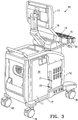
- FIGS 1-5 illustrate a biopsy system 10 that embodies features of the invention.
- the system 10 has a tissue removal system 11, an imaging system 12, display screen 13 and a common input console 14 with a keyboard 15 and a touchscreen display 16.
- the biopsy system 10 is mounted on a cart 17 which has wheels 18 at each corner for portability.
- the input console 14 has probe holders 20 for holding ultrasonic probes and tissue removal probes (not shown).
- the tissue removal system 11 has connecting modules 21 and 22 that are configured to receive tissue removal probes (not shown) such as the probes for EnCor® and SenoCor 360® probes which are available from SenoRx, Inc., the present assignee.
- the imaging system 12 has connecting modules 23, 24 and 25 for connecting with different suitable ultrasonic probes, such as broadband transducers L 14-5/38, L 14-5W/60 and C 5-2/60 available from Ultrasonix Medical Corporation.
- the first two are linear array type transducers and the latter is a curved array type transducer.
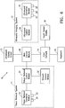
- FIG. 6 is a general block diagram of the biopsy system 10 shown in Figure 1 which has a tissue removal system 11, an ultrasonic imaging system 12 and a main computer module 30 and an image display screen.
- the tissue removal system 11 of system 10 has a tissue removal control module 31, a vacuum control module 32 for vacuum operations and tissue removal connector module 33 probe connectors 21 and 22.
- the vacuum control module 32 has a vacuum line, a valve operated by the tissue removal control module 31 and a vacuum source (e.g. a connection to a vacuum line or a vacuum pump) which are not shown.
- the imaging system 12 has an ultrasound control module 34 for ultrasonic emission and reception and an interface with the main computer module 30.
- An ultrasound connector module 35 is in communication with the ultrasound control module and has ultrasound probe connectors 23, 24 and 25.
- Output from the main computer module 30 related to the imaging input data thereto from the ultrasound control module is directed through a communication link to the image display screen 13 to display ultrasonic diagnostic images from an ultrasonic probe (not shown) connected to one of the ultrasound probe connectors 23, 24 or 25.
- the input console 14 is connected via a communication link to the main computer module 30 which in turn has communication links to the tissue removal control module 31 and the ultrasound control module 34. This allows the single input console 14 to be employed to control both the tissue removal system 11 and the imaging system 12.
- the main display screen 13 is positioned right above the input console 14 so that a single operator may easily operate both the tissue removal system 11 and the ultrasound imaging system 12 from a single console. Further details of the tissue removal system can be found in patents and published applications of SenoRx, Inc. previously referred.
- the ultrasound imaging system 12 for producing ultrasound images has ultrasound control module 34 is coupled to a ultrasound connector module 35 has probe connectors 23, 24 and 24 to which may be connected an ultrasound probe (not shown)
- the probe generates and receives acoustic signals.
- the acoustic signals that are generated by the probe are directed towards a body region of a patient, e.g. breast, and some of the acoustic signals are reflected back to the probe as echo signals.
- the echo signals obtained by the probe are sent back to the ultrasound control module 34 which processes the echo signals to extract data that is sent to the main computer module 30.
- the main computer module 30 performs a display data processing in real-time which is sent to the ultrasound display screen 13 where an ultrasound diagnostic image is displayed. See U.S. Pat. No. 6,325,759 , for example.
- Input console 14 allows the user to interact with the main computer module and modify the ultrasound configuration. Further details of the ultrasound imaging system can be found in the patents and published applications of Ultrasonix previously referred to.
- the vacuum control module 32 and the tissue removal control modules 32 are shown.
- additional modules may be provided, for example modules for a temperature probe, a heart rate monitor device, a drug infusion tools, anesthesia tools, or other surgical or medical devices that may operate with the biopsy system 10. They may be connected to the tissue removal control module 31 or directly to the main computer module 30.
- the tissue removal devices connected to the tissue removal connector module 33 may have mechanical tissue cutting members or radio frequency (RF) powered electrosurgical cutting members for performing the surgery.
- RF radio frequency
- the tissue removal control module 31 is a microprocessor-based electrical device with built-in software functions necessary to operate various handheld devices for both tissue removal.
- Each handheld device preferably contains a software script, stored in a memory device within the handheld device, for operating that particular device when connected to the tissue removal control module.
- the said software script may be stored in non-volatile memories such as erasable programmable read only memories (EPROMs), electrically erasable programmable read only memories (EEPROMs) or flash memories.
- EPROMs erasable programmable read only memories
- EEPROMs electrically erasable programmable read only memories
- flash memories such as erasable programmable read only memories (EPROMs), electrically erasable programmable read only memories (EEPROMs) or flash memories.
- GUI graphical user interface
- the various modules and the handheld devices for either the tissue removal system 11 or the ultrasound image system 12 may be interconnected through wired connections (including connector modules and wires) for their operations, the communication links can be easily implemented through wireless communications.
- the conventional wired connections have certain advantages such as low signal interferences, but the wireless technology can turn the operation of the handheld device to a more mobile operation, which benefits the operator as well.
- almost all the control signals can be sent through a predetermined wireless communication channel using technologies such as Bluetooth or 802.11 compliant wireless technologies.
- the handheld device is battery powered, then the operation may be completely mobile.
- the wired communication channels may be used together with the wireless communication channels so that the tissue removal control module can take advantage of the available wireless technologies for providing convenience to the operator, while still benefiting from using some conventional wired technologies.
- the examples provided herein illustrate embodiments having features of the invention, it should be understood that communications between devices can take various forms and the main computer module 30, the tissue removal control module 31 and the ultrasound control module 33 are designed to use the most practical technologies for fulfilling the need of the operators.
- the biopsy system may be powered by a single power source (not shown) or can have multiple power sources for various functions.
- the tissue removal system 11 and the ultrasound imaging system 12 may have separate power sources.
Landscapes
- Health & Medical Sciences (AREA)
- Life Sciences & Earth Sciences (AREA)
- Surgery (AREA)
- Biomedical Technology (AREA)
- General Health & Medical Sciences (AREA)
- Heart & Thoracic Surgery (AREA)
- Medical Informatics (AREA)
- Molecular Biology (AREA)
- Veterinary Medicine (AREA)
- Animal Behavior & Ethology (AREA)
- Engineering & Computer Science (AREA)
- Public Health (AREA)
- Pathology (AREA)
- Nuclear Medicine, Radiotherapy & Molecular Imaging (AREA)
- Physics & Mathematics (AREA)
- Biophysics (AREA)
- Radiology & Medical Imaging (AREA)
- Ultra Sonic Daignosis Equipment (AREA)
- Surgical Instruments (AREA)
Claims (19)
- Biopsiesystem (10), umfassend eine bewegliche Basis (17), ein Gewebeentnahmesystem (11) auf der beweglichen Basis, ein Abbildungssystem (12) auf der beweglichen Basis, ein Bildanzeigesystem (13), um Bilder anzuzeigen, die durch das Abbildungssystem aufgenommen wurden, und zumindest eine Eingabekonsole (14), wobei die Eingabekonsole (14) eine gemeinsame Eingabekonsole für das Gewebeentnahmesystem und das Abbildungssystem ist,
wobei das Gewebeentnahmesystem (11) eine Vielzahl von Verbindermodulen (21, 22) aufweist, um ein Verbinden von verschiedenen Gewebeentnahmesonden mit dem Gewebeentnahmesystem zu vereinfachen,
das Gewebeentnahmesystem (11) ein programmierbares Gewebeentnahmesteuermodul (31), zumindest ein Vakuumsteuermodul (32) zum Bereitstellen eines Vakuums an das Gewebeentnahmesystem, und die Vielzahl von Verbindermodulen, die konfiguriert sind, um die verschiedenen Gewebeentnahmesonden zu empfangen, umfasst, wobei das Vakuumsteuermodul (32) eine Vakuumleitung aufweist, die konfiguriert ist, um die Gewebeentnahmesonde und ein Flusssteuerventil, das durch das Gewebeentnahmesteuermodul (31) gesteuert wird, in der Vakuumleitung in Eingriff zu bringen, um ein Vakuum innerhalb einer mit einem Verbindermodul (21, 22) verbundenen Gewebeentnahmesonde für das Gewebeentnahmesystem (11) aufzubauen, wobei das Vakuumsteuermodul (32) eine Vakuumquelle in Kommunikation mit der Vakuumleitung beinhaltet, und
die Vielzahl von Verbindermodulen (21, 22) konfiguriert sind, um die verschiedenen Gewebeentnahmesonden zu empfangen, die in einer Speichervorrichtung innerhalb der jeweiligen Gewebeentnahmesonde abgespeicherte Softwarescripte, um die Gewebeentnahmesonde zu betreiben, die Funktionalitäten der Gewebeentnahmesonde zu steuern und um dem Gewebeentnahmesteuermodul Informationen bereitzustellen, wenn sie damit verbunden sind, aufweisen. - Biopsiesystem (10) nach Anspruch 1,
wobei das Gewebeentnahmesystem weiter die verschiedenen Gewebeentnahmesonden umfasst,
wobei die verschiedenen Gewebeentnahmesonden in einer Speichervorrichtung innerhalb der jeweiligen Gewebeentnahmesonde abgespeicherte Softwarescripte, um die Gewebeentnahmesonde zu betreiben, die Funktionalitäten der Gewebeentnahmesonde zu steuern und um dem Gewebeentnahmesteuermodul (31) Informationen bereitzustellen, wenn sie damit verbunden sind, aufweisen. - Biopsiesystem nach Anspruch 1 oder 2, wobei das Gewebeentnahmesystem (11) das Gewebeentnahmesteuermodul (31), ein Gewebeentnahmeverbindermodul (33), das konfiguriert ist, um eine erste Kommunikationsverknüpfung zwischen einer Gewebeentnahmesonde und dem Gewebeentnahmesteuermodul zu bilden, aufweist.
- Biopsiesystem nach Anspruch 1, wobei das Gewebeentnahmesystem eine zweite Kommunikationsverknüpfung zwischen dem Vakuumsteuermodul (32) und dem Gewebeentnahmesteuermodul (31) aufweist.
- Biopsiesystem nach Anspruch 1 oder 2, wobei das Abbildungssystem ein Ultraschallabbildungssystem ist.
- Biopsiesystem nach Anspruch 5, wobei das Ultraschallabbildungssystem ein Ultraschallsteuermodul (34), ein Verbindermodul (35), das konfiguriert ist, um eine Kommunikationsverknüpfung zwischen einer Ultraschallabbildungssonde und dem Ultraschallsteuermodul zu bilden, aufweist.
- Biopsiesystem nach Anspruch 6, wobei das Abbildungssystem einen Bildanzeigebildschirm (13) aufweist, der konfiguriert ist, um ein Ultraschallbild basierend auf von einer Ultraschallsonde empfangenen Daten anzuzeigen.
- Biopsiesystem nach Anspruch 7, wobei die gemeinsame Eingabekonsole Steuerinformationen für das Ultraschallsteuermodul des Abbildungssystems und, um Steuerinformationen für das Gewebeentnahmesteuermodul des Gewebeentnahmesystems bereitzustellen, bereitstellt.
- Biopsiesystem nach Anspruch 1 oder 2, beinhaltend ein Hauptcomputermodul (30), das eine Kommunikationsverknüpfung zwischen dem Gewebeentnahmesteuermodul und dem Ultraschallabbildungssteuermodul aufweist.
- Biopsiesystem nach Anspruch 9, beinhaltend eine dritte Kommunikationsverknüpfung zwischen dem Hauptcomputermodul und dem Gewebeentnahmesteuermodul.
- Biopsiesystem nach Anspruch 10, beinhaltend eine vierte Kommunikationsverknüpfung zwischen dem Hauptcomputermodul und dem Ultraschallsteuermodul.
- Biopsiesystem nach Anspruch 10, wobei die Kommunikationsverknüpfung zwischen dem Hauptcomputermodul und dem Gewebeentnahmesteuermodul ein serielles Kabel ist.
- Biopsiesystem nach Anspruch 6, wobei das Ultraschallabbildungssystem ein Schnittstellenmodul in Kommunikation zwischen dem Ultraschallsteuermodul und dem Hauptcomputermodul beinhaltet.
- Biopsiesystem nach Anspruch 1 oder 2, wobei das Abbildungssystem eine Vielzahl von Verbindermodulen (23, 24, 25) aufweist, um ein Verbinden verschiedener Abbildungssonden mit dem Abbildungssystem zu vereinfachen.
- Biopsiesystem nach Anspruch 1 oder 2, wobei die bewegliche Basis ein Rollwagen ist.
- Biopsiesystem nach Anspruch 1 oder 2, wobei das Gewebeentnehmesystem innerhalb eines ersten Gehäuses auf der beweglichen Basis enthalten ist, wobei, vorzugsweise, das Vakuumsteuermodul innerhalb des Gehäuses für das Gewebeentnahmesystem enthalten ist.
- Biopsiesystem nach Anspruch 1 oder 2, wobei das Abbildungssystem innerhalb eines zweiten Gehäuses auf der beweglichen Basis enthalten ist.
- Biopsiesystem nach Anspruch 1 oder 2, wobei das Abbildungssystem und das Gewebeentnahmesystem gleichzeitig betriebsbereit sind.
- Biopsiesystem nach Anspruch 17, wobei das Hauptcomputermodul innerhalb des Gehäuses für das Abbildungssystem enthalten ist.
Applications Claiming Priority (2)
| Application Number | Priority Date | Filing Date | Title |
|---|---|---|---|
| US81090606P | 2006-06-05 | 2006-06-05 | |
| PCT/US2007/013208 WO2007145926A2 (en) | 2006-06-05 | 2007-06-05 | Biopsy system with integrated ultrasonic imaging |
Publications (2)
| Publication Number | Publication Date |
|---|---|
| EP2023820A2 EP2023820A2 (de) | 2009-02-18 |
| EP2023820B1 true EP2023820B1 (de) | 2019-03-20 |
Family
ID=38832322
Family Applications (1)
| Application Number | Title | Priority Date | Filing Date |
|---|---|---|---|
| EP07795749.6A Not-in-force EP2023820B1 (de) | 2006-06-05 | 2007-06-05 | Biopsiesystem mit integrierter ultraschallabbildung |
Country Status (9)
| Country | Link |
|---|---|
| US (3) | US8622907B2 (de) |
| EP (1) | EP2023820B1 (de) |
| KR (1) | KR101458067B1 (de) |
| CN (1) | CN101453956A (de) |
| AU (1) | AU2007258679B2 (de) |
| BR (1) | BRPI0712375B8 (de) |
| CA (2) | CA3044203C (de) |
| RU (1) | RU2008151403A (de) |
| WO (1) | WO2007145926A2 (de) |
Cited By (2)
| Publication number | Priority date | Publication date | Assignee | Title |
|---|---|---|---|---|
| US12588893B2 (en) | 2012-03-26 | 2026-03-31 | Teratech Corporation | Tablet ultrasound system |
| US12616445B2 (en) | 2016-11-16 | 2026-05-05 | Teratech Corporation | Portable ultrasound system |
Families Citing this family (33)
| Publication number | Priority date | Publication date | Assignee | Title |
|---|---|---|---|---|
| AU2007258679B2 (en) * | 2006-06-05 | 2013-02-21 | Senorx, Inc. | Biopsy system with integrated ultrasonic imaging |
| US8071933B2 (en) * | 2007-06-18 | 2011-12-06 | Gotohti.Com Inc | Photochromic optically keyed dispenser |
| US20090253998A1 (en) * | 2008-04-03 | 2009-10-08 | Convergent Medical Solutions, Inc. | Skin biopsy with suturing prior to resection |
| US20090253997A1 (en) * | 2008-04-03 | 2009-10-08 | Convergent Medical Solutions, Inc. | Skin biopsy with automated lesion stabilization and resection |
| KR101496909B1 (ko) | 2009-01-22 | 2015-02-27 | 삼성전자 주식회사 | 로봇 |
| KR101496910B1 (ko) * | 2009-01-22 | 2015-02-27 | 삼성전자 주식회사 | 로봇 |
| KR101010597B1 (ko) * | 2009-04-14 | 2011-01-24 | 주식회사 메디슨 | 생검장치 분리형 초음파 진단장치 |
| USD650482S1 (en) * | 2010-11-16 | 2011-12-13 | Samsung Electronics Co., Ltd. | Ultrasonic diagnostic equipment |
| EP2673738A4 (de) | 2011-02-11 | 2017-08-23 | E-4 Endeavors, Inc. | System und verfahren zum modellieren von biopsieproben |
| US9119586B2 (en) * | 2011-05-12 | 2015-09-01 | B-K Medical Aps | Ultrasound imaging system |
| CN102319087B (zh) * | 2011-07-13 | 2015-06-03 | 无锡祥生医学影像有限责任公司 | 触摸屏超声诊断仪及其脉冲波多普勒模式调节方法 |
| EP2744415B1 (de) | 2011-09-29 | 2020-06-24 | Koninklijke Philips N.V. | Ultraschalldiagnostik- bilderzeugungssystem mit einem kontextabhängigen bedienfeld |
| US9180898B2 (en) * | 2011-09-30 | 2015-11-10 | Hitachi Aloka Medical, Ltd. | Cart for portable ultrasonic diagnostic device and ultrasonic diagnostic unit |
| WO2014080311A1 (en) * | 2012-11-26 | 2014-05-30 | Koninklijke Philips N.V. | Projection data de-noising |
| US9677869B2 (en) | 2012-12-05 | 2017-06-13 | Perimeter Medical Imaging, Inc. | System and method for generating a wide-field OCT image of a portion of a sample |
| USD716949S1 (en) | 2013-04-26 | 2014-11-04 | Kabushiki Kaisha Toshiba | Ultrasonic diagnosis apparatus |
| USD713035S1 (en) * | 2013-05-30 | 2014-09-09 | Samsung Medison Co., Ltd | Ultrasonic diagnostic apparatus |
| USD711539S1 (en) * | 2013-06-26 | 2014-08-19 | Koninklijke Philips N.V. | Trolley for medical diagnostic imaging system |
| USD728791S1 (en) * | 2013-10-09 | 2015-05-05 | Hitachi Aloka Medical, Ltd. | Ultrasound diagnosis apparatus |
| USD727504S1 (en) * | 2013-10-09 | 2015-04-21 | Hitachi Aloka Medical, Ltd. | Ultrasound diagnosis apparatus |
| DE102013226342B4 (de) * | 2013-12-18 | 2022-10-13 | Siemens Healthcare Gmbh | Medizintechnische Anlage |
| US10314563B2 (en) | 2014-11-26 | 2019-06-11 | Devicor Medical Products, Inc. | Graphical user interface for biopsy device |
| CN104634952A (zh) * | 2015-02-15 | 2015-05-20 | 翟艳萍 | 脑血管疾病诊断检测装置 |
| JP1563659S (de) * | 2016-03-17 | 2016-11-21 | ||
| USD857210S1 (en) * | 2016-09-05 | 2019-08-20 | Optimedica Corporation | Base with wheels for a mobile patient bed |
| EP3534798B1 (de) * | 2016-11-03 | 2020-08-05 | B-K Medical ApS | Sondenkabelhalter |
| CN110573108B (zh) | 2017-05-12 | 2021-04-06 | Devicor医疗产业收购公司 | 带有尖端保护器和安装设备的活检装置 |
| EP3655748B1 (de) | 2017-07-18 | 2023-08-09 | Perimeter Medical Imaging, Inc. | Probenbehälter zur stabilisierung und ausrichtung exzidierter biologischer gewebeproben zur ex-vivo-analyse |
| EP3935647A1 (de) * | 2019-04-26 | 2022-01-12 | Devicor Medical Products, Inc. | Benutzerschnittstelle für biopsievorrichtung |
| USD945624S1 (en) * | 2020-05-07 | 2022-03-08 | GE Precision Healthcare LLC | Controller |
| USD933231S1 (en) * | 2020-05-07 | 2021-10-12 | GE Precision Healthcare LLC | Controller |
| DE102021215054B3 (de) | 2021-12-28 | 2023-03-16 | Siemens Healthcare Gmbh | Probeentnahmesystem zum Entnehmen wenigstens eines Materialpartikels |
| US12480602B2 (en) * | 2023-08-17 | 2025-11-25 | Channel Master, Llc | Cable/tubular clamp and system using the same |
Family Cites Families (91)
| Publication number | Priority date | Publication date | Assignee | Title |
|---|---|---|---|---|
| US3844272A (en) | 1969-02-14 | 1974-10-29 | A Banko | Surgical instruments |
| JPS5869527A (ja) | 1981-10-20 | 1983-04-25 | 富士写真フイルム株式会社 | 高周波メスおよび高周波メスを用いた内視鏡 |
| GB8324442D0 (en) | 1983-09-13 | 1983-10-12 | Matburn Holdings Ltd | Electrosurgical system |
| US4658819A (en) | 1983-09-13 | 1987-04-21 | Valleylab, Inc. | Electrosurgical generator |
| US4878493A (en) | 1983-10-28 | 1989-11-07 | Ninetronix Venture I | Hand-held diathermy apparatus |
| US4739759A (en) | 1985-02-26 | 1988-04-26 | Concept, Inc. | Microprocessor controlled electrosurgical generator |
| EP0225973A3 (de) | 1985-11-01 | 1988-06-29 | Hewlett-Packard Company | Messkopf elektromagnetischer Felder |
| DE3703218A1 (de) | 1987-01-31 | 1988-08-11 | Licentia Gmbh | Strombegrenzung fuer einen dreiphasigen, mit einer folgeregelung betriebenen wechselrichter |
| US5335671A (en) * | 1989-11-06 | 1994-08-09 | Mectra Labs, Inc. | Tissue removal assembly with provision for an electro-cautery device |
| US5415169A (en) | 1989-11-21 | 1995-05-16 | Fischer Imaging Corporation | Motorized mammographic biopsy apparatus |
| US5159929A (en) | 1990-06-14 | 1992-11-03 | Morris G Ronald | Insulated rf shield |
| US6022347A (en) | 1991-08-12 | 2000-02-08 | Karl Storz Gmbh & Co. | High-frequency surgical generator for adjusted cutting and coagulation |
| EP0598780B1 (de) | 1991-08-12 | 1999-03-03 | Karl Storz GmbH & Co. | Hochfrequenzchirurgiegenerator zum schneiden von geweben |
| US5697882A (en) | 1992-01-07 | 1997-12-16 | Arthrocare Corporation | System and method for electrosurgical cutting and ablation |
| US5305760A (en) | 1992-02-07 | 1994-04-26 | Interflo Medical Inc. | Method for rejecting electrical interference from physiological measurements |
| US5400267A (en) | 1992-12-08 | 1995-03-21 | Hemostatix Corporation | Local in-device memory feature for electrically powered medical equipment |
| IL107523A (en) | 1993-11-07 | 2000-01-31 | Ultraguide Ltd | Articulated needle guide for ultrasound imaging and method of using same |
| AU3221095A (en) | 1994-08-02 | 1996-03-04 | Gabriel Bernaz | Flexible probe for high frequency skin treatment |
| US5814044A (en) | 1995-02-10 | 1998-09-29 | Enable Medical Corporation | Apparatus and method for morselating and removing tissue from a patient |
| EP0836433A1 (de) | 1995-06-06 | 1998-04-22 | Valleylab, Inc. | Digitale wellenformerzeugung für elektrochirgische generatoren |
| US5617857A (en) | 1995-06-06 | 1997-04-08 | Image Guided Technologies, Inc. | Imaging system having interactive medical instruments and methods |
| US5640956A (en) | 1995-06-07 | 1997-06-24 | Neovision Corporation | Methods and apparatus for correlating ultrasonic image data and radiographic image data |
| US5785708A (en) | 1995-09-19 | 1998-07-28 | Lp Systems Corporation | Epilator probeholder |
| US5772659A (en) | 1995-09-26 | 1998-06-30 | Valleylab Inc. | Electrosurgical generator power control circuit and method |
| US5615682A (en) * | 1995-10-26 | 1997-04-01 | Hewlett-Packard Company | Ultrasound transducer cable management system |
| US5769086A (en) | 1995-12-06 | 1998-06-23 | Biopsys Medical, Inc. | Control system and method for automated biopsy device |
| US6458121B1 (en) | 1996-03-19 | 2002-10-01 | Diapulse Corporation Of America | Apparatus for athermapeutic medical treatments |
| DE19623840A1 (de) | 1996-06-14 | 1997-12-18 | Berchtold Gmbh & Co Geb | Elektrochirurgischer Hochfrequenz-Generator |
| US5836943A (en) | 1996-08-23 | 1998-11-17 | Team Medical, L.L.C. | Electrosurgical generator |
| US6117126A (en) | 1996-08-29 | 2000-09-12 | Bausch & Lomb Surgical, Inc. | Surgical module with independent microprocessor-based communication |
| WO1998014129A1 (en) | 1996-09-30 | 1998-04-09 | Minnesota Mining And Manufacturing Company | Powered surgical instruments and control unit |
| US6063035A (en) * | 1997-07-24 | 2000-05-16 | Fuji Photo Optical Co., Ltd. | Coupling adaptor for endoscopically inserting ultrasound probe |
| WO1999040856A1 (en) | 1998-02-10 | 1999-08-19 | Biosense Inc. | Improved catheter calibration |
| US6331166B1 (en) * | 1998-03-03 | 2001-12-18 | Senorx, Inc. | Breast biopsy system and method |
| US6162216A (en) | 1998-03-02 | 2000-12-19 | Guziak; Robert Andrew | Method for biopsy and ablation of tumor cells |
| US6454727B1 (en) * | 1998-03-03 | 2002-09-24 | Senorx, Inc. | Tissue acquisition system and method of use |
| US6347241B2 (en) * | 1999-02-02 | 2002-02-12 | Senorx, Inc. | Ultrasonic and x-ray detectable biopsy site marker and apparatus for applying it |
| US6540695B1 (en) | 1998-04-08 | 2003-04-01 | Senorx, Inc. | Biopsy anchor device with cutter |
| US6161034A (en) * | 1999-02-02 | 2000-12-12 | Senorx, Inc. | Methods and chemical preparations for time-limited marking of biopsy sites |
| WO2002039917A1 (en) * | 1998-05-14 | 2002-05-23 | Calypso Medical, Inc. | Systems and methods for locating and defining a target location within a human body |
| WO2000051484A2 (en) * | 1998-11-25 | 2000-09-08 | Fischer Imaging Corporation | User interface system for mammographic imager |
| US6725083B1 (en) * | 1999-02-02 | 2004-04-20 | Senorx, Inc. | Tissue site markers for in VIVO imaging |
| US6120462A (en) * | 1999-03-31 | 2000-09-19 | Ethicon Endo-Surgery, Inc. | Control method for an automated surgical biopsy device |
| US6203541B1 (en) | 1999-04-23 | 2001-03-20 | Sherwood Services Ag | Automatic activation of electrosurgical generator bipolar output |
| GB9911956D0 (en) | 1999-05-21 | 1999-07-21 | Gyrus Medical Ltd | Electrosurgery system and method |
| US20030181898A1 (en) | 1999-05-28 | 2003-09-25 | Bowers William J. | RF filter for an electrosurgical generator |
| US6981941B2 (en) | 1999-06-02 | 2006-01-03 | Power Medical Interventions | Electro-mechanical surgical device |
| US6391024B1 (en) | 1999-06-17 | 2002-05-21 | Cardiac Pacemakers, Inc. | RF ablation apparatus and method having electrode/tissue contact assessment scheme and electrocardiogram filtering |
| US6607528B1 (en) | 1999-06-22 | 2003-08-19 | Senorx, Inc. | Shapeable electrosurgical scalpel |
| JP2003526407A (ja) | 1999-09-08 | 2003-09-09 | キューロン メディカル,インコーポレイテッド | 1組の治療デバイスを制御するシステム |
| US6238388B1 (en) | 1999-09-10 | 2001-05-29 | Alan G. Ellman | Low-voltage electrosurgical apparatus |
| US6325759B1 (en) | 1999-09-23 | 2001-12-04 | Ultrasonix Medical Corporation | Ultrasound imaging system |
| US6500119B1 (en) * | 1999-12-01 | 2002-12-31 | Medical Tactile, Inc. | Obtaining images of structures in bodily tissue |
| US6432065B1 (en) | 1999-12-17 | 2002-08-13 | Ethicon Endo-Surgery, Inc. | Method for using a surgical biopsy system with remote control for selecting and operational mode |
| US6428487B1 (en) * | 1999-12-17 | 2002-08-06 | Ethicon Endo-Surgery, Inc. | Surgical biopsy system with remote control for selecting an operational mode |
| US20040181219A1 (en) | 2000-02-08 | 2004-09-16 | Gyrus Medical Limited | Electrosurgical instrument and an electrosugery system including such an instrument |
| EP1157667A3 (de) | 2000-05-25 | 2003-07-02 | Ethicon Endo-Surgery, Inc. | Elektrochirurgischer Generator mit Verringerung von RF Lecksignalen |
| WO2002024082A2 (en) | 2000-09-24 | 2002-03-28 | Medtronic Inc | Motor control system for a surgical handpiece |
| AU2001295433A1 (en) | 2000-10-09 | 2002-04-22 | Benca Technology Aps | A surgical workstation |
| DE10051244A1 (de) * | 2000-10-17 | 2002-05-16 | Philips Corp Intellectual Pty | Röntgenfreies intravaskuläres Lokalisierungs- und Bildgebungsverfahren |
| US20050004559A1 (en) * | 2003-06-03 | 2005-01-06 | Senorx, Inc. | Universal medical device control console |
| US6620157B1 (en) | 2000-12-28 | 2003-09-16 | Senorx, Inc. | High frequency power source |
| US6632183B2 (en) | 2001-02-12 | 2003-10-14 | Thermal Technologies, Inc. | Perfusion sensitive biopsy extractor |
| JP2002320325A (ja) | 2001-04-18 | 2002-10-31 | Toenec Corp | 送配電装置 |
| US6524247B2 (en) * | 2001-05-15 | 2003-02-25 | U-Systems, Inc. | Method and system for ultrasound imaging of a biopsy needle |
| US6733458B1 (en) * | 2001-09-25 | 2004-05-11 | Acuson Corporation | Diagnostic medical ultrasound systems and methods using image based freehand needle guidance |
| AU2002327779B2 (en) | 2001-09-28 | 2008-06-26 | Angiodynamics, Inc. | Impedance controlled tissue ablation apparatus and method |
| KR20030033318A (ko) | 2001-10-20 | 2003-05-01 | (주)에이치비메디컬스 | 지방 흡입 및 지방층 측정 시스템 |
| US6860855B2 (en) * | 2001-11-19 | 2005-03-01 | Advanced Imaging Technologies, Inc. | System and method for tissue biopsy using ultrasonic imaging |
| US6824516B2 (en) * | 2002-03-11 | 2004-11-30 | Medsci Technologies, Inc. | System for examining, mapping, diagnosing, and treating diseases of the prostate |
| US6960209B2 (en) | 2002-10-23 | 2005-11-01 | Medtronic, Inc. | Electrosurgical methods and apparatus for making precise incisions in body vessels |
| US20050119646A1 (en) | 2002-11-13 | 2005-06-02 | Artemis Medical, Inc. | Devices and methods for controlling movement of an electrosurgical electrode |
| CA2505727A1 (en) | 2002-11-13 | 2004-05-27 | Artemis Medical, Inc. | Devices and methods for controlling initial movement of an electrosurgical electrode |
| US7697972B2 (en) * | 2002-11-19 | 2010-04-13 | Medtronic Navigation, Inc. | Navigation system for cardiac therapies |
| US7274325B2 (en) | 2002-12-23 | 2007-09-25 | Ultrasonix Medical Corporation | Optimized method of performing spatial transformation |
| US6911008B2 (en) | 2003-02-19 | 2005-06-28 | Ultrasonix Medical Corporation | Compound ultrasound imaging method |
| DE10327237A1 (de) | 2003-06-17 | 2005-01-13 | Trumpf Medizin Systeme Gmbh + Co. Kg | Elektrochirurgisches Instrument für ein Endoskop |
| US20050261591A1 (en) * | 2003-07-21 | 2005-11-24 | The Johns Hopkins University | Image guided interventions with interstitial or transmission ultrasound |
| US8403828B2 (en) * | 2003-07-21 | 2013-03-26 | Vanderbilt University | Ophthalmic orbital surgery apparatus and method and image-guide navigation system |
| JP2005102750A (ja) | 2003-09-26 | 2005-04-21 | Olympus Corp | 電気手術用電源装置 |
| DE502004009815D1 (de) | 2003-10-29 | 2009-09-10 | Celon Ag Medical Instruments | Medizingerät für die Elektrotomie |
| WO2005060849A1 (en) | 2003-11-20 | 2005-07-07 | Sherwood Services Ag | Electrosurgical pencil with plurality of controls |
| US9408592B2 (en) | 2003-12-23 | 2016-08-09 | Senorx, Inc. | Biopsy device with aperture orientation and improved tip |
| US20080004526A1 (en) * | 2004-09-15 | 2008-01-03 | Scientific Biopsy Ltd. | Breast Cancer Detection and Biopsy |
| JP2008514363A (ja) * | 2004-09-30 | 2008-05-08 | ボストン サイエンティフィック リミテッド | 電気外科用途において使用するための多機能内視鏡システム |
| US8795195B2 (en) | 2004-11-29 | 2014-08-05 | Senorx, Inc. | Graphical user interface for tissue biopsy system |
| US20070282221A1 (en) * | 2006-06-02 | 2007-12-06 | U-Systems, Inc. | Ultrasound assisted and x-ray assisted biopsy devices |
| AU2007258679B2 (en) * | 2006-06-05 | 2013-02-21 | Senorx, Inc. | Biopsy system with integrated ultrasonic imaging |
| KR101075363B1 (ko) | 2008-10-31 | 2011-10-19 | 정창욱 | 최소 침습 수술 도구를 포함하는 수술용 로봇 시스템 |
| KR100947491B1 (ko) | 2009-08-07 | 2010-03-17 | 주식회사 래보 | 외과 수술용 장치의 인스트루먼트 |
| KR101123129B1 (ko) * | 2010-03-31 | 2012-03-20 | 한양대학교 산학협력단 | 로봇암 및 이를 포함하는 수술용 로봇 |
-
2007
- 2007-06-05 AU AU2007258679A patent/AU2007258679B2/en not_active Ceased
- 2007-06-05 CA CA3044203A patent/CA3044203C/en active Active
- 2007-06-05 EP EP07795749.6A patent/EP2023820B1/de not_active Not-in-force
- 2007-06-05 US US11/810,425 patent/US8622907B2/en not_active Expired - Fee Related
- 2007-06-05 BR BRPI0712375A patent/BRPI0712375B8/pt not_active IP Right Cessation
- 2007-06-05 WO PCT/US2007/013208 patent/WO2007145926A2/en not_active Ceased
- 2007-06-05 CN CNA2007800195120A patent/CN101453956A/zh active Pending
- 2007-06-05 RU RU2008151403/14A patent/RU2008151403A/ru not_active Application Discontinuation
- 2007-06-05 CA CA2662789A patent/CA2662789C/en active Active
- 2007-06-05 KR KR1020097000075A patent/KR101458067B1/ko not_active Expired - Fee Related
- 2007-10-30 US US11/980,308 patent/US20080132789A1/en not_active Abandoned
-
2014
- 2014-01-06 US US14/148,605 patent/US9375204B2/en not_active Expired - Fee Related
Non-Patent Citations (1)
| Title |
|---|
| None * |
Cited By (2)
| Publication number | Priority date | Publication date | Assignee | Title |
|---|---|---|---|---|
| US12588893B2 (en) | 2012-03-26 | 2026-03-31 | Teratech Corporation | Tablet ultrasound system |
| US12616445B2 (en) | 2016-11-16 | 2026-05-05 | Teratech Corporation | Portable ultrasound system |
Also Published As
| Publication number | Publication date |
|---|---|
| US9375204B2 (en) | 2016-06-28 |
| CA2662789C (en) | 2019-07-02 |
| US8622907B2 (en) | 2014-01-07 |
| US20080132789A1 (en) | 2008-06-05 |
| CA3044203C (en) | 2023-04-04 |
| KR101458067B1 (ko) | 2014-11-04 |
| CA3044203A1 (en) | 2007-12-21 |
| RU2008151403A (ru) | 2010-07-20 |
| AU2007258679A1 (en) | 2007-12-21 |
| AU2007258679B2 (en) | 2013-02-21 |
| US20080009728A1 (en) | 2008-01-10 |
| BRPI0712375B1 (pt) | 2020-03-03 |
| WO2007145926A3 (en) | 2008-04-03 |
| CN101453956A (zh) | 2009-06-10 |
| BRPI0712375A2 (pt) | 2012-06-12 |
| BRPI0712375B8 (pt) | 2021-06-22 |
| EP2023820A2 (de) | 2009-02-18 |
| US20140121504A1 (en) | 2014-05-01 |
| WO2007145926A2 (en) | 2007-12-21 |
| CA2662789A1 (en) | 2007-12-21 |
| KR20090027722A (ko) | 2009-03-17 |
Similar Documents
| Publication | Publication Date | Title |
|---|---|---|
| CA3044203C (en) | Biopsy system with integrated ultrasonic imaging | |
| US6645148B2 (en) | Ultrasonic probe including pointing devices for remotely controlling functions of an associated imaging system | |
| JP6657273B2 (ja) | 超音波プローブおよび整列された針ガイドシステム | |
| US8920325B2 (en) | Handheld ultrasound imaging systems | |
| EP2113201B1 (de) | Bewegliches Ultraschallelement zur Verwendung in medizinischen Diagnosevorrichtungen | |
| CN100382766C (zh) | 超声诊断装置与操作设备 | |
| JP6986966B2 (ja) | マルチセンサ超音波プローブ | |
| CN101433473B (zh) | 具有单屏触摸面板的便携式成像系统 | |
| EP3335636B1 (de) | Sondenvorrichtung, medizinisches instrument damit und steuerungsverfahren der sondenvorrichtung | |
| CN102258385B (zh) | 图像诊断方法及装置 | |
| US20090012394A1 (en) | User interface for ultrasound system | |
| CN102266236B (zh) | 超声波诊断装置以及图像信息管理装置 | |
| CN104994792A (zh) | 超声波诊断装置以及医用图像处理装置 | |
| EP3292820B1 (de) | Ultraschallabbildungsvorrichtung und verfahren zur steuerung davon | |
| CN202761314U (zh) | 超声波探头固定用保持适配器及超声波诊断装置 | |
| CN221949845U (zh) | 一种超声诊断设备 | |
| JP2007215921A (ja) | 超音波診断装置及び超音波プローブ |
Legal Events
| Date | Code | Title | Description |
|---|---|---|---|
| PUAI | Public reference made under article 153(3) epc to a published international application that has entered the european phase |
Free format text: ORIGINAL CODE: 0009012 |
|
| 17P | Request for examination filed |
Effective date: 20081111 |
|
| AK | Designated contracting states |
Kind code of ref document: A2 Designated state(s): AT BE BG CH CY CZ DE DK EE ES FI FR GB GR HU IE IS IT LI LT LU LV MC MT NL PL PT RO SE SI SK TR |
|
| AX | Request for extension of the european patent |
Extension state: AL BA HR MK RS |
|
| DAX | Request for extension of the european patent (deleted) | ||
| RAP1 | Party data changed (applicant data changed or rights of an application transferred) |
Owner name: SENORX, INC. |
|
| 17Q | First examination report despatched |
Effective date: 20150421 |
|
| STAA | Information on the status of an ep patent application or granted ep patent |
Free format text: STATUS: EXAMINATION IS IN PROGRESS |
|
| REG | Reference to a national code |
Ref country code: DE Ref legal event code: R079 Ref document number: 602007057905 Country of ref document: DE Free format text: PREVIOUS MAIN CLASS: A61B0008000000 Ipc: A61B0090000000 |
|
| GRAP | Despatch of communication of intention to grant a patent |
Free format text: ORIGINAL CODE: EPIDOSNIGR1 |
|
| STAA | Information on the status of an ep patent application or granted ep patent |
Free format text: STATUS: GRANT OF PATENT IS INTENDED |
|
| RIC1 | Information provided on ipc code assigned before grant |
Ipc: A61B 90/00 20160101AFI20180926BHEP |
|
| INTG | Intention to grant announced |
Effective date: 20181024 |
|
| GRAS | Grant fee paid |
Free format text: ORIGINAL CODE: EPIDOSNIGR3 |
|
| RIC1 | Information provided on ipc code assigned before grant |
Ipc: A61B 90/00 20160101AFI20180926BHEP |
|
| GRAA | (expected) grant |
Free format text: ORIGINAL CODE: 0009210 |
|
| STAA | Information on the status of an ep patent application or granted ep patent |
Free format text: STATUS: THE PATENT HAS BEEN GRANTED |
|
| AK | Designated contracting states |
Kind code of ref document: B1 Designated state(s): AT BE BG CH CY CZ DE DK EE ES FI FR GB GR HU IE IS IT LI LT LU LV MC MT NL PL PT RO SE SI SK TR |
|
| REG | Reference to a national code |
Ref country code: GB Ref legal event code: FG4D |
|
| REG | Reference to a national code |
Ref country code: CH Ref legal event code: EP |
|
| REG | Reference to a national code |
Ref country code: DE Ref legal event code: R096 Ref document number: 602007057905 Country of ref document: DE |
|
| REG | Reference to a national code |
Ref country code: AT Ref legal event code: REF Ref document number: 1109698 Country of ref document: AT Kind code of ref document: T Effective date: 20190415 |
|
| REG | Reference to a national code |
Ref country code: IE Ref legal event code: FG4D |
|
| REG | Reference to a national code |
Ref country code: NL Ref legal event code: MP Effective date: 20190320 |
|
| PG25 | Lapsed in a contracting state [announced via postgrant information from national office to epo] |
Ref country code: FI Free format text: LAPSE BECAUSE OF FAILURE TO SUBMIT A TRANSLATION OF THE DESCRIPTION OR TO PAY THE FEE WITHIN THE PRESCRIBED TIME-LIMIT Effective date: 20190320 Ref country code: LT Free format text: LAPSE BECAUSE OF FAILURE TO SUBMIT A TRANSLATION OF THE DESCRIPTION OR TO PAY THE FEE WITHIN THE PRESCRIBED TIME-LIMIT Effective date: 20190320 Ref country code: SE Free format text: LAPSE BECAUSE OF FAILURE TO SUBMIT A TRANSLATION OF THE DESCRIPTION OR TO PAY THE FEE WITHIN THE PRESCRIBED TIME-LIMIT Effective date: 20190320 |
|
| REG | Reference to a national code |
Ref country code: LT Ref legal event code: MG4D |
|
| PG25 | Lapsed in a contracting state [announced via postgrant information from national office to epo] |
Ref country code: NL Free format text: LAPSE BECAUSE OF FAILURE TO SUBMIT A TRANSLATION OF THE DESCRIPTION OR TO PAY THE FEE WITHIN THE PRESCRIBED TIME-LIMIT Effective date: 20190320 Ref country code: LV Free format text: LAPSE BECAUSE OF FAILURE TO SUBMIT A TRANSLATION OF THE DESCRIPTION OR TO PAY THE FEE WITHIN THE PRESCRIBED TIME-LIMIT Effective date: 20190320 Ref country code: BG Free format text: LAPSE BECAUSE OF FAILURE TO SUBMIT A TRANSLATION OF THE DESCRIPTION OR TO PAY THE FEE WITHIN THE PRESCRIBED TIME-LIMIT Effective date: 20190620 Ref country code: GR Free format text: LAPSE BECAUSE OF FAILURE TO SUBMIT A TRANSLATION OF THE DESCRIPTION OR TO PAY THE FEE WITHIN THE PRESCRIBED TIME-LIMIT Effective date: 20190621 |
|
| REG | Reference to a national code |
Ref country code: AT Ref legal event code: MK05 Ref document number: 1109698 Country of ref document: AT Kind code of ref document: T Effective date: 20190320 |
|
| PG25 | Lapsed in a contracting state [announced via postgrant information from national office to epo] |
Ref country code: ES Free format text: LAPSE BECAUSE OF FAILURE TO SUBMIT A TRANSLATION OF THE DESCRIPTION OR TO PAY THE FEE WITHIN THE PRESCRIBED TIME-LIMIT Effective date: 20190320 Ref country code: SK Free format text: LAPSE BECAUSE OF FAILURE TO SUBMIT A TRANSLATION OF THE DESCRIPTION OR TO PAY THE FEE WITHIN THE PRESCRIBED TIME-LIMIT Effective date: 20190320 Ref country code: PT Free format text: LAPSE BECAUSE OF FAILURE TO SUBMIT A TRANSLATION OF THE DESCRIPTION OR TO PAY THE FEE WITHIN THE PRESCRIBED TIME-LIMIT Effective date: 20190720 Ref country code: CZ Free format text: LAPSE BECAUSE OF FAILURE TO SUBMIT A TRANSLATION OF THE DESCRIPTION OR TO PAY THE FEE WITHIN THE PRESCRIBED TIME-LIMIT Effective date: 20190320 Ref country code: RO Free format text: LAPSE BECAUSE OF FAILURE TO SUBMIT A TRANSLATION OF THE DESCRIPTION OR TO PAY THE FEE WITHIN THE PRESCRIBED TIME-LIMIT Effective date: 20190320 Ref country code: IT Free format text: LAPSE BECAUSE OF FAILURE TO SUBMIT A TRANSLATION OF THE DESCRIPTION OR TO PAY THE FEE WITHIN THE PRESCRIBED TIME-LIMIT Effective date: 20190320 Ref country code: EE Free format text: LAPSE BECAUSE OF FAILURE TO SUBMIT A TRANSLATION OF THE DESCRIPTION OR TO PAY THE FEE WITHIN THE PRESCRIBED TIME-LIMIT Effective date: 20190320 |
|
| PG25 | Lapsed in a contracting state [announced via postgrant information from national office to epo] |
Ref country code: PL Free format text: LAPSE BECAUSE OF FAILURE TO SUBMIT A TRANSLATION OF THE DESCRIPTION OR TO PAY THE FEE WITHIN THE PRESCRIBED TIME-LIMIT Effective date: 20190320 |
|
| PG25 | Lapsed in a contracting state [announced via postgrant information from national office to epo] |
Ref country code: IS Free format text: LAPSE BECAUSE OF FAILURE TO SUBMIT A TRANSLATION OF THE DESCRIPTION OR TO PAY THE FEE WITHIN THE PRESCRIBED TIME-LIMIT Effective date: 20190720 Ref country code: AT Free format text: LAPSE BECAUSE OF FAILURE TO SUBMIT A TRANSLATION OF THE DESCRIPTION OR TO PAY THE FEE WITHIN THE PRESCRIBED TIME-LIMIT Effective date: 20190320 |
|
| REG | Reference to a national code |
Ref country code: DE Ref legal event code: R097 Ref document number: 602007057905 Country of ref document: DE |
|
| PLBE | No opposition filed within time limit |
Free format text: ORIGINAL CODE: 0009261 |
|
| STAA | Information on the status of an ep patent application or granted ep patent |
Free format text: STATUS: NO OPPOSITION FILED WITHIN TIME LIMIT |
|
| PG25 | Lapsed in a contracting state [announced via postgrant information from national office to epo] |
Ref country code: DK Free format text: LAPSE BECAUSE OF FAILURE TO SUBMIT A TRANSLATION OF THE DESCRIPTION OR TO PAY THE FEE WITHIN THE PRESCRIBED TIME-LIMIT Effective date: 20190320 Ref country code: MC Free format text: LAPSE BECAUSE OF FAILURE TO SUBMIT A TRANSLATION OF THE DESCRIPTION OR TO PAY THE FEE WITHIN THE PRESCRIBED TIME-LIMIT Effective date: 20190320 |
|
| REG | Reference to a national code |
Ref country code: CH Ref legal event code: PL |
|
| 26N | No opposition filed |
Effective date: 20200102 |
|
| PG25 | Lapsed in a contracting state [announced via postgrant information from national office to epo] |
Ref country code: SI Free format text: LAPSE BECAUSE OF FAILURE TO SUBMIT A TRANSLATION OF THE DESCRIPTION OR TO PAY THE FEE WITHIN THE PRESCRIBED TIME-LIMIT Effective date: 20190320 |
|
| REG | Reference to a national code |
Ref country code: BE Ref legal event code: MM Effective date: 20190630 |
|
| PG25 | Lapsed in a contracting state [announced via postgrant information from national office to epo] |
Ref country code: TR Free format text: LAPSE BECAUSE OF FAILURE TO SUBMIT A TRANSLATION OF THE DESCRIPTION OR TO PAY THE FEE WITHIN THE PRESCRIBED TIME-LIMIT Effective date: 20190320 |
|
| PG25 | Lapsed in a contracting state [announced via postgrant information from national office to epo] |
Ref country code: IE Free format text: LAPSE BECAUSE OF NON-PAYMENT OF DUE FEES Effective date: 20190605 |
|
| PG25 | Lapsed in a contracting state [announced via postgrant information from national office to epo] |
Ref country code: LI Free format text: LAPSE BECAUSE OF NON-PAYMENT OF DUE FEES Effective date: 20190630 Ref country code: CH Free format text: LAPSE BECAUSE OF NON-PAYMENT OF DUE FEES Effective date: 20190630 Ref country code: BE Free format text: LAPSE BECAUSE OF NON-PAYMENT OF DUE FEES Effective date: 20190630 Ref country code: LU Free format text: LAPSE BECAUSE OF NON-PAYMENT OF DUE FEES Effective date: 20190605 |
|
| PG25 | Lapsed in a contracting state [announced via postgrant information from national office to epo] |
Ref country code: CY Free format text: LAPSE BECAUSE OF FAILURE TO SUBMIT A TRANSLATION OF THE DESCRIPTION OR TO PAY THE FEE WITHIN THE PRESCRIBED TIME-LIMIT Effective date: 20190320 |
|
| PG25 | Lapsed in a contracting state [announced via postgrant information from national office to epo] |
Ref country code: MT Free format text: LAPSE BECAUSE OF FAILURE TO SUBMIT A TRANSLATION OF THE DESCRIPTION OR TO PAY THE FEE WITHIN THE PRESCRIBED TIME-LIMIT Effective date: 20190320 Ref country code: HU Free format text: LAPSE BECAUSE OF FAILURE TO SUBMIT A TRANSLATION OF THE DESCRIPTION OR TO PAY THE FEE WITHIN THE PRESCRIBED TIME-LIMIT; INVALID AB INITIO Effective date: 20070605 |
|
| REG | Reference to a national code |
Ref country code: FR Ref legal event code: PLFP Year of fee payment: 16 |
|
| PGFP | Annual fee paid to national office [announced via postgrant information from national office to epo] |
Ref country code: GB Payment date: 20220520 Year of fee payment: 16 Ref country code: FR Payment date: 20220519 Year of fee payment: 16 Ref country code: DE Payment date: 20220518 Year of fee payment: 16 |
|
| REG | Reference to a national code |
Ref country code: DE Ref legal event code: R119 Ref document number: 602007057905 Country of ref document: DE |
|
| GBPC | Gb: european patent ceased through non-payment of renewal fee |
Effective date: 20230605 |
|
| PG25 | Lapsed in a contracting state [announced via postgrant information from national office to epo] |
Ref country code: DE Free format text: LAPSE BECAUSE OF NON-PAYMENT OF DUE FEES Effective date: 20240103 Ref country code: GB Free format text: LAPSE BECAUSE OF NON-PAYMENT OF DUE FEES Effective date: 20230605 |
|
| PG25 | Lapsed in a contracting state [announced via postgrant information from national office to epo] |
Ref country code: FR Free format text: LAPSE BECAUSE OF NON-PAYMENT OF DUE FEES Effective date: 20230630 |