EP2024141B1 - Fabrication d'une micropince au moyen d'un procédé de séparation de matériaux - Google Patents
Fabrication d'une micropince au moyen d'un procédé de séparation de matériaux Download PDFInfo
- Publication number
- EP2024141B1 EP2024141B1 EP07723161A EP07723161A EP2024141B1 EP 2024141 B1 EP2024141 B1 EP 2024141B1 EP 07723161 A EP07723161 A EP 07723161A EP 07723161 A EP07723161 A EP 07723161A EP 2024141 B1 EP2024141 B1 EP 2024141B1
- Authority
- EP
- European Patent Office
- Prior art keywords
- material layer
- sacrificial layer
- layer
- gripper
- microgripper
- Prior art date
- Legal status (The legal status is an assumption and is not a legal conclusion. Google has not performed a legal analysis and makes no representation as to the accuracy of the status listed.)
- Not-in-force
Links
Images




Classifications
-
- B—PERFORMING OPERATIONS; TRANSPORTING
- B25—HAND TOOLS; PORTABLE POWER-DRIVEN TOOLS; MANIPULATORS
- B25J—MANIPULATORS; CHAMBERS PROVIDED WITH MANIPULATION DEVICES
- B25J7/00—Micromanipulators
-
- B—PERFORMING OPERATIONS; TRANSPORTING
- B25—HAND TOOLS; PORTABLE POWER-DRIVEN TOOLS; MANIPULATORS
- B25J—MANIPULATORS; CHAMBERS PROVIDED WITH MANIPULATION DEVICES
- B25J19/00—Accessories fitted to manipulators, e.g. for monitoring, for viewing; Safety devices combined with or specially adapted for use in connection with manipulators
- B25J19/007—Means or methods for designing or fabricating manipulators
-
- B—PERFORMING OPERATIONS; TRANSPORTING
- B81—MICROSTRUCTURAL TECHNOLOGY
- B81C—PROCESSES OR APPARATUS SPECIALLY ADAPTED FOR THE MANUFACTURE OR TREATMENT OF MICROSTRUCTURAL DEVICES OR SYSTEMS
- B81C99/00—Subject matter not provided for in other groups of this subclass
- B81C99/0005—Apparatus specially adapted for the manufacture or treatment of microstructural devices or systems, or methods for manufacturing the same
- B81C99/002—Apparatus for assembling MEMS, e.g. micromanipulators
-
- H—ELECTRICITY
- H01—ELECTRIC ELEMENTS
- H01J—ELECTRIC DISCHARGE TUBES OR DISCHARGE LAMPS
- H01J37/00—Discharge tubes with provision for introducing objects or material to be exposed to the discharge, e.g. for the purpose of examination or processing thereof
- H01J37/02—Details
- H01J37/20—Means for supporting or positioning the object or the material; Means for adjusting diaphragms or lenses associated with the support
Definitions
- the invention relates to a micro-gripper for receiving and holding micrometer or submicrometer-scale objects and to a method for producing the same.
- micro grippers are used in numerous fields today.
- micro-grippers are used in micro- and nanotechnology for manipulation and assembly or for joining micro-objects.
- Further fields of application for microgrippers can be found in physics, biology, chemistry and medicine, micro-grippers being used, for example, in the analysis and examination of samples for picking up, gripping and holding the samples.
- the micro-grippers are usually made of a base body which is connected to two or more movable and / or elastic gripping elements, which serve for receiving and holding an object.
- an actuator provided on the micro-gripper is usually provided, which moves the counteracting gripping elements.
- micro-grippers partially acting on the object gripping forces can be adjusted or regulated by appropriate control of the actuator.
- micro grippers without actuators are known in which the recording and holding of an object is not active but passive taking advantage of elastic material properties.
- Micro-grippers of this type have at least two opposite, from each other spaced gripping elements between which an object is clamped. By trapping an object between the gripping elements they are elastically deformed and thus generate the elastic holding forces retroactively on the object.
- micro gripper on the versions with only two gripping elements.
- a micro-gripper for micro-assembly which consists of a base body, a piezotranslator attached to the base body as a linear actuator and a microstructure body connected to the base body and the piezotranslator.
- the microstructure body are two oppositely acting, opposing gripping elements and a mechanical lever translation with bending joints, for increasing the transmission of a linear movement of the piezotranslator on the gripping elements, structurally combined in one component.
- the elastic bending elements deform and thus initiate a targeted movement apart or towards one another of the gripping elements.
- the microstructure body is produced from a (100) silicon wafer polished on both sides with a thickness of 240 ⁇ m by means of the known structuring processes, lithography and anisotropic etching. Subsequently, the microstructure body is fixed on the base body, a silicon substrate, by means of adhesive in such a way that only selected small contact surfaces are glued between the microstructure body and the base body, wherein the bending elements and the gripping elements are axially displaceable along the contact surfaces.
- the production of the microstructure body made of silicon, especially its good microstructure and no plastic deformation of silicon is particularly emphasized.
- piezoelectric for example.
- Piezoresistive to convert the gripping force into an electrical signal and thereby the gripping force to the to adjust the object to be gripped.
- Further embodiments of micro-grippers which use piezosystems as actuators are, for example, the publications DE 196 48 165 A1 such as DE 101 14 551 C1 refer to.
- microgripper applications in the context of material analysis of micrometer or submicron-scale samples, in particular any contamination of the sample by the microgripper, for example by a transfer of material from one preceding sample to the next sample, must be prevented. Therefore, for example, for gripping and holding samples in the course of investigation, in particular with electron microscopes, such as transmission electron microscopes (TEM) or Scanning Electron Microscopes (SEM), using new microgrippers for each sample. Since microgrippers are intended for single-use use only, they should be inexpensive to mass-produce. Nevertheless, they must meet all requirements to ensure reliable gripping and holding in such applications. However, the above-described microgrippers are not or not optimally suited for this purpose.
- micro-grippers with actuators is in the document US 2002/0166976 A1 , which is particularly suitable for use for gripping and holding a sample in the context of studies with TEM.
- the micro-gripper described therein consists of a rod-shaped or cylindrical elongated body which has one or more receiving slots on three sides at one end such that a sample can be clamped in the receiving slot.
- the receiving and holding of the sample is based, as described above, on the elastic deformation of the material surrounding the receiving slot and the restoring force thereby caused on the clamped sample.
- the starting material is a piece of straight tungsten wire with a wire diameter of 50 microns.
- an end region of the tungsten wire is first of all processed by means of electropolishing or an etching process such that the tungsten wire tapers in this end region towards the wire end to a diameter of a few micrometers.
- a receiving slot open towards the end of the tapered region is worked out from the now conically tapered end region of the tungsten wire by means of an ion beam impinging perpendicularly to the longitudinal axis of the tungsten wire.
- a second receiving slot rotated by 90 degrees thereto can be worked out. This creates in the rejuvenated End region of the tungsten wire at least two or four gripping elements between which an object is clamped.
- the receiving slot has an embodiment according to a width of 2 microns and a depth of 30 microns.
- From the DE 195 22 004 is a manufacturing method of partially movable microstructures on the basis of a dry chemical etched sacrificial layer, wherein the mostly consisting of polyimide sacrificial layer is applied directly to a substrate layer on which, completely spaced by the sacrificial layer to the substrate layer, a further teilbewegliche microstructured material layer, eg. is applied in a further training as a cantilever with or without an additional tip.
- the sacrificial layer located between the cantilever layer and the substrate is only partially removed by a dry chemical etching process so that a remnant of sacrificial layer remains as a type of spacer.
- a micro gripper can be removed, which provides two TiNi existing gripper jaws, which together define a receiving slot on both sides.
- a layer of shape-memory metal (SMA) is applied to the surface of the upper gripper jaw, a material that is capable of deforming by appropriate electrical power in a manner whereby the gripper jaws move from a closed to an open position and vice versa are transferable. It can be seen from the gripper jaw illustrations which can be seen from the publication that the one gripper jaw is connected in one piece with the substrate made of silicon.
- micro-gripper should in particular be inexpensive to produce as a mass-produced, in the idle state at the gripping elements parallel aligned, opposing clamping surfaces and are suitable for receiving, transporting and holding samples of material in their investigation in a TEM or SEM.
- Claim 1 specifies a method for producing a micro-gripper comprising a base body and a gripping body integrally connected to the base body, which projects beyond the base body and a receiving slot at a free end portion such that for gripping and holding a micrometer or submicrometer -skaliges object is clamped in the receiving slot.
- the method is characterized essentially by the fact that the base body and the gripping body are produced by means of a material deposition method to form at least a common first and a common second material layer, and that the material layers are substantially planar and interconnected become.
- Claim 8 specifies a micro gripper produced by a method according to claim 1, which is characterized essentially by the fact that the base body and the gripping body are formed as a uniform flat body which is delimited by two substantially flat, mutually parallel and overlapping flat body surfaces is.
- An essential idea of the invention lies in the production of a micro gripper according to the preamble of claim 1, by means of a material deposition method with formation of at least two newly formed and interconnected material layers. Methods of depositing material are well known to those skilled in the art. For the production of a micro gripper according to the invention, methods from thin-film technology are particularly suitable, by means of which materials can be applied to a substrate in thin layers, with layer thicknesses of less than 1 .mu.m.
- PVD physical vapor deposition
- CVD chemical vapor deposition
- LPCVD low-pressure CVD
- DE plasma-enhanced CVD
- the layers deposited therewith can be subsequently patterned by masking or lithography processes with subsequent material removal by application of wet chemical etching, reactive ion etching (RIE), sputter etching, ion beam etching or plasma etching.
- RIE reactive ion etching
- sputter etching ion beam etching or plasma etching.
- the structuring of a layer to be applied can also be achieved by a targeted local material deposition. Furthermore, by depositing a so-called sacrificial layer between two material layers and the subsequent removal of the sacrificial layers, for example by wet etching, an almost arbitrary three-dimensional structuring of the on the substrate applied material layers can be achieved.
- a so-called sacrificial layer between two material layers and the subsequent removal of the sacrificial layers for example by wet etching
- an almost arbitrary three-dimensional structuring of the on the substrate applied material layers can be achieved. The person skilled in the art is familiar with these techniques and their application.
- the production method for the micro-gripper in a simple case consists of the following method steps.
- a planar substrate surface is provided.
- a silicon substrate is preferably suitable because of its good surface planarity.
- a first sacrificial layer is applied to the substrate surface.
- the first material layer is applied to the first sacrificial layer.
- the application (and possibly the structuring) of the second sacrificial layer to the first material layer, at least to a local region of the first material layer takes place.
- the major part of the first material layer is not covered by the second sacrificial layer.
- the second sacrificial layer corresponds to their order on one local area in their outer dimensions of the receiving slot to be produced on the gripping body, so that after removal of the second sacrificial layer in this area, the receiving slot is exposed.
- the second material layer is applied to the second sacrificial layer and the regions of the first material layer not covered by the second sacrificial layer.
- the first and second material layers with the exception of one local area, are directly connected to one another.
- the first and second sacrificial layers are removed. The removal of the second sacrificial layer forms the receiving slot, the removal of the first sacrificial layer dissolves the now finished micro-gripper from the substrate.
- wet-chemical etching processes are suitable for removing the sacrificial layers.
- a micro-gripper according to claim 8 is obtained, which is essentially characterized in that the base body and the gripping body of the micro gripper are formed as a uniform flat body, which is bounded by two substantially planar, parallel to each other and overlapping flat body surfaces.
- the outer free surfaces of the first and second material layers correspond to the flat body surfaces.
- the receiving slot on the gripping body has on the inside preferably two mutually parallel, spaced-apart and overlapping clamping surfaces.
- the clamping surfaces preferably have a spacing of 10 nm to 10 .mu.m, in particular from 50 nm to 1 .mu.m from each other.
- the lateral dimensioning of the flat body surfaces, and thus the lateral shapes of the base body, of the gripping body and ultimately also of the clamping surfaces in the receiving slot, is effected by a corresponding structuring of the layers formed in the context of the material separation method described.
- a corresponding structuring of the layers formed in the context of the material separation method described.
- Corresponding structuring methods are known to the person skilled in the art.
- Such a structuring of the layers makes it possible, in particular, to specify the lateral dimensioning of the micro gripper to be produced almost arbitrarily and thus to adapt the shape of the base body, the gripping body and the clamping surfaces to the desired requirements.
- microgrippers are preferably produced whose flat body surfaces in each case completely overlap. Furthermore, the method according to the invention preferably produces microgrippers which are dimensioned and designed such that they can receive and hold samples which are to be examined, for example, by means of a TEM or SEM, and that they can be inserted directly into a commercially available sample holder of a TEM or SEM can be inserted.
- micro-grippers in which the flat-body surfaces are a circular sector are particularly suitable correspond to a center angle ⁇ ⁇ 180 degrees and the gripping body at a Kreissektorspitze the Kreissector is outstanding or whose flat surfaces correspond to a circular segment with a center angle ⁇ ⁇ 180 degrees and the gripping body on the circle segment, especially in the middle of the circle segment tendon, the circle segment protruding is, and the circular segment or the circular sector has a circle radius which is adapted to a radius of a sample holder of a microscope, in particular a SEM or TEM.
- the sample holder radius is typically 1.5 mm.
- the flat body surfaces may correspond to a polygon, wherein the gripping body is arranged projecting a peripheral edge of the polygon, or have any other shapes.
- the structuring of the first and second material layers determines the shape and relative position of the clamping surfaces on the receiving slot.
- the clamping surfaces correspond to a polygon, in particular a rectangle or square and overlap each other completely.
- clamping surfaces which taper in the direction of the opening of the receiving slot are also suitable for particular applications.
- the following materials can be used for the sacrificial layers: plastic, metal or, in particular, silicon oxide.
- the following materials can be used for the material layers: plastics, ceramics, metal, semimetal or in particular polysilicon.
- the use of the specified materials for the sacrificial layers or the material layers is not arbitrary.
- the person skilled in the corresponding material combinations, which are known for described Materialabscheide- and sacrificial layer technology, known. Particularly suitable has the Pairing of sacrificial layers of silicon oxide and material layers of polysilicon proven.
- first and the second material layer may also consist of different materials and thus impart special mechanical, electrical, magnetic or chemical properties to the microgripper according to the invention due to the different material properties of the first and the second material layer.
- micro-grippers are particularly suitable for picking up, transporting and holding material samples as part of their investigation in a TEM or SEM.
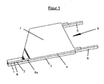
- the flat body 8 consists of a first material layer 3 and a second, connected to the first material layer 3 material layer 4.
- the flat body 8 can be in a base body area with the associated flat body surface part 7 and a Greif redesignBereich with the gripping elements 1 and 2, between which the receiving slot 6 is divided.
- a continuous gap 6a running transversely to the gripping elements 1, 2 is provided in the connection region between the base body and gripping body. This serves to improve the initiation of forces, which are created by an elastic deformation of the gripping elements 1, 2, in the material layers 3 and 4.
- thin webs 5 are provided for mounting the micro gripper on the substrate 9.
- the flat body surface 7 serves as an adapter surface, for example for receiving the micro gripper in a handling system (transport manipulator), or for insertion into the receiving unit of an analysis device (SEM, TEM). In the present case, it has the shape of a polygon. However, the flat body surface can be optimally dimensioned in the context of the manufacturing process according to the given requirements.
- FIGS. 2a and 2b show the operation of the micro-gripper 8. Shown are the gripper body region of the micro-gripper 8 with the gripping elements 1, 2 and the gripping elements 1, 2 receiving slot 6, and a material sample 10, on which a slope 11 is provided.
- the micro gripper 8 with the gripping elements 1, 2 is brought from above onto the bevel 11 of the material sample 10.
- the bevel 11 serves an optimal adhesion between the gripping elements 1, 2 and the material sample 10. Basically, such a slope is not required.
- FIG. 2b shows that the gripping elements 1, 2 are pushed over the slope 11 of the material sample and thereby spread.
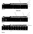
- FIGS. 3a and 3b the microgripper goes off FIG. 1 shown in the manufacturing phase after the sacrificial layers have been removed.
- FIG. 3a first shows a plan view of the micro-gripper 8.
- the micro-gripper 8 is connected via the webs 5 with a holding portion 20. Since the holding region 20 is firmly connected to the substrate 9 (not shown) even after the sacrificial layers have been removed, the micro gripper 8 completely detached from the substrate 9 is still held by the holding region 20 via the webs 5. Unintentional release or loss of the micro-gripper 8 after removing the sacrificial layers can thus be prevented. To detach the micro gripper only the webs 5 are to be cut.
- the number, the arrangement and the cross section (width and height) of the webs 5 depends essentially on the holding force that is to be absorbed by the webs.
- the FIG. 3b shows a section through the layer structure along the section line A-A '. It can clearly be seen that the substrate 9 is still firmly connected to the holding region 20 even after the removal of the sacrificial layers.
- the micro-gripper 8 consists of the first material layer 3 and the second material layer 4, which are connected to each other.
- the removed sacrificial layers have exposed the receiving slot 6 and the gap 6a.
- the micro-gripper 8 is connected to the holding region 20 via the webs 5, which are formed from the first material layer.
- Micro-grippers 8 can be used to pick up and hold objects in the micrometer and sub-micron range.
- a special application of the micro gripper is the inclusion of electron-transparent samples for their subsequent examination in a TEM or SEM. Such samples are prepared by means of the technique known as the so-called Focused Ion Beam technique (FIB technique) from a material to be examined.
- FIB technique Focused Ion Beam technique
- FIG. 5 The conventional method of picking up such a TEM sample 40 uses a needle 41 which is attached to the TEM sample 40 by means of material deposition.
- the micro-gripper 8 produced according to the invention makes it possible to use an electron-transparent sample 40 produced by means of FIB technology with the gripping elements 1, 2 in a FIB preparation system corresponding to FIGS FIGS. 2a and 2b take.
- FIG. 6 shows the microgripper 8 and the TEM sample 40 clamped between the gripping elements 1, 2.
- the TEM sample 40 can be taken directly into the TEM and is immediately available for examination with the electron beam 53 in the correct position.
- the main advantage of this approach is that the complicated previously used so-called lift-out process is replaced by the single gripping of the TEM sample 40 by the micro gripper. After picking up the TEM sample 40, it can be examined together with the micro gripper in the TEM. If necessary, after the TEM sample has been picked up by the microgripper, post-processing of the TEM sample in the FIB preparation unit is possible.
- the TEM sample 40 is dimensioned by means of the FIB technique so that at the later contact surface to the micro-gripper 8, the sample thickness required for holding is achieved. The remainder of the TEM sample is prepared for the electron transparency necessary for the TEM examination.
- FIGS. 7a and 7b show a further advantageous embodiment of the micro-gripper according to the invention 8.
- the micro-gripper 8 is used in conjunction with a half-ring 70 having an inner radius and an outer radius.
- the microgripper 8 has a flat base body in the form of a circular sector, wherein the gripping body with the TEM sample 40 at the circular sector tip is arranged projecting the sector of the circle.
- the radius of the circular sector of the base body shape is greater than the inner radius of the half ring 70.
- the outer radius of the half ring 70 and the radius of the circular sector of the base body is the same.
- the micro-gripper 8 is picked up by means of a device, for example a vacuum pipette, and fastened on the half-ring 70 by means of an adhesive, as shown.
- This half-ring 70 can consist of different materials which are used in the TEM analysis.
- the gripping elements 1, 2 project over the half ring, so that this arrangement is suitable for picking up TEM samples 40 from a substrate.
- FIG. 7b shows in a detail magnification, the inclusion of such a TEM sample 40 from a suitably prepared substrate.
- differently shaped micro-grippers can also be fastened on the half-ring 70.
- the outer shape of the base body therefore does not necessarily have to be similar to a circular cutout.
- FIG. 8 shows an embodiment of the micro gripper 8 according to the invention, in which the base body is formed with a semicircular flat body surface 7.
- the radius R of this semicircle is dimensioned such that a subsequent direct transfer of the microgripper 8 into the sample holder of the TEM can take place.
- the microgripper 8 is first held by a receiving device 31 and thus the recording of the TEM sample 40 is performed. This arrangement allows the direct adoption of the micro gripper 8 in the sample holder of the TEM, without any additional adaptation to a semi-circular ring is made.
- the holder of the microgrippers in the sample holder is designed of the TE microscope difficult because the micro gripper can slip laterally and thus is not properly taken from the clamping nut of the sample holder.
Landscapes
- Engineering & Computer Science (AREA)
- Robotics (AREA)
- Mechanical Engineering (AREA)
- Manufacturing & Machinery (AREA)
- Microelectronics & Electronic Packaging (AREA)
- Chemical & Material Sciences (AREA)
- Analytical Chemistry (AREA)
- Micromachines (AREA)
- Manipulator (AREA)
- Sampling And Sample Adjustment (AREA)
- Chemical Vapour Deposition (AREA)
Claims (15)
- Procédé de fabrication d'une micro-griffe (8), comprenant un corps de base, ainsi qu'un corps de préhension relié en monobloc avec le corps de base qui saillit par-dessus le corps de base et qui sur une zone d'extrémité libre prévoit une encoche de réception (6) de telle sorte que pour la préhension et le maintien, un objet de dimensions de l'ordre des micromètres ou des sous-micromètres soit susceptible d'être serré dans l'encoche de réception (6),
le corps de base et le corps de préhension étant fabriqués au moyen d'un procédé de séparation de matières, en formant au moins une première couche de matière commune et une deuxième couche de matière commune (3, 4) et en ce que les couches de matières (3, 4) sont sensiblement réalisées de manière plane et sont reliées les unes aux autres par réalisation des étapes de procédé suivantes :- mise à disposition d'une surface de substrat plane- application d'une première couche sacrificielle (13) sur la surface du substrat,- application de la première couche de matière (3) sur la première couche sacrificielle (13),- application locale d'une deuxième couche sacrificielle (14) sur la première couche de matière (3), au moins sur la zone locale correspondant à l'encoche de réception de la première couche de matière (3),- application de la deuxième couche de matière (4) sur la deuxième couche sacrificielle (14), ainsi que sur les zones non recouvertes de la première couche de matière (3),- retrait de la deuxième couche sacrificielle (14) pour créer l'encoche de réception et- retrait de la première couche sacrificielle (13) pour détacher complètement la micro-griffe fabriquée de la surface du substrat. - Procédé selon la revendication 1,
caractérisé en ce que l'application de la première couche sacrificielle (13) s'effectue dans au moins une zone de surface localement limitée sur la surface du substrat, et/ou en ce qu'après l'application de la première couche sacrificielle (13) sur la surface du substrat, il est procédé à une structuration de la première couche sacrificielle (13). - Procédé selon la revendication 1 ou 2,
caractérisé en ce que l'application de la première couche de matière (3) sur la première couche sacrificielle (13) s'effectue sur au moins une zone de surface localement limitée sur la première couche sacrificielle (13) et/ou en ce qu'après l'application de la première couche de matière (3) sur la première couche sacrificielle (13), il est procédé à une structuration de la première couche de matière (3). - Procédé selon l'une quelconque des revendications 1 à 3,
caractérisé en ce qu'après l'application de la deuxième couche sacrificielle (14) sur la première couche de matière (3), il est procédé à une structuration de la deuxième couche de matière (14). - Procédé selon l'une quelconque des revendications 1 à 4,
caractérisé en ce que l'application de la deuxième couche de matière (4) sur la deuxième couche sacrificielle (14), ainsi que de la première couche de matière (3) s'effectue dans au moins une zone de surface limitée localement sur la première couche sacrificielle (14) ainsi que de la première couche de matière (3) et/ou en ce qu'après l'application de la deuxième couche de matière (4) sur la deuxième couche sacrificielle (14) ainsi que de la première couche de matière (3), il est effectué une structuration de la deuxième couche de matière (4). - Procédé selon l'une quelconque des revendications 1 à 5,
caractérisé en ce qu'avant l'application de la première couche sacrificielle (13) sur la surface du substrat, on applique une ou plusieurs couches intermédiaires (12) sur la surface du substrat. - Procédé selon l'une quelconque des revendications 1 à 6,
caractérisé en ce que sur la deuxième couche de matière (4) on applique une ou plusieurs couches de stabilisation (15). - Micro-griffe fabriquée à l'aide d'un procédé selon l'une quelconque des revendications 1 à 7, comprenant un corps de base, ainsi qu'un corps de préhension relié en monobloc avec le corps de base, qui saillit par dessus le corps de base et qui sur une zone d'extrémité libre prévoit une encoche de réception (6), de telle sorte que pour la préhension et le maintien, un objet de dimensions de l'ordre des micromètres ou des sous-micromètres soit susceptible d'être serré dans l'encoche de réception (6),
le corps de base et le corps de préhension étant conçus comme un corps plat homogène (8) qui est exclusivement limité par deux surfaces de corps plat sensiblement planes, orientées à la parallèle l'une de l'autre et se chevauchant et qui est susceptible d'être fabriquée en utilisant un procédé de séparation de matière, dans lequel on relie directement l'une à l'autre par zones au moins une première et une deuxième couche de matière (3, 4). - Micro-griffe selon la revendication 8,
caractérisée en ce que les surfaces de corps plats se chevauchent entièrement. - Micro-griffe selon la revendication 8 ou 9
caractérisée en ce que les surfaces de corps plats correspondent à un secteur de cercle avec un angle du centre α ≤ à 180 degrés et en ce que le corps de préhension est disposé sur une pointe du secteur de cercle, en saillissant par-dessus le secteur de cercle. - Micro-griffe selon l'une quelconque des revendications 8 ou 9,
caractérisée en ce que les surfaces de corps plats correspondent à un segment de cercle avec un angle du centre α ≤ à 180 degrés et en ce que le corps de préhension est disposé sur la corde du segment de cercle, notamment au centre de la corde du segment de cercle, en débordant par-dessus le segment de cercle. - Micro-griffe selon la revendication 8 ou 9,
caractérisée en ce que les surfaces de corps plats correspondent à un polygone et en ce que le corps de préhension est disposé≤ à 180 degrés en saillissant par-dessus un bord périphérique du polygone. - Micro-griffe selon l'une quelconque des revendications 10 ou 11,
caractérisée en ce que le segment de cercle ou le secteur de cercle comporte un rayon de courbure qui est adapté à un rayon d'une fixation d'essai d'un microscope, notamment d'un microscope SE ou TE. - Micro-griffe selon l'une quelconque des revendications 8 à 13,
caractérisée en ce que l'encoche de réception (6) comporte à l'intérieur deux surfaces de serrage disposées en parallèle l'une de l'autre, écartées l'une de l'autre et se chevauchant. - Utilisation de la micro-griffe selon l'une quelconque des revendications 8 à 14 pour prendre, transporter et maintenir des échantillons de matières dans le cadre de leur analyse dans un microscope TE.
Applications Claiming Priority (2)
| Application Number | Priority Date | Filing Date | Title |
|---|---|---|---|
| DE102006023768A DE102006023768A1 (de) | 2006-05-20 | 2006-05-20 | Mikrogreifer |
| PCT/EP2007/002109 WO2007134660A1 (fr) | 2006-05-20 | 2007-03-09 | Fabrication d'une micropince au moyen d'un procédé de séparation de matériaux |
Publications (2)
| Publication Number | Publication Date |
|---|---|
| EP2024141A1 EP2024141A1 (fr) | 2009-02-18 |
| EP2024141B1 true EP2024141B1 (fr) | 2009-10-07 |
Family
ID=38289939
Family Applications (1)
| Application Number | Title | Priority Date | Filing Date |
|---|---|---|---|
| EP07723161A Not-in-force EP2024141B1 (fr) | 2006-05-20 | 2007-03-09 | Fabrication d'une micropince au moyen d'un procédé de séparation de matériaux |
Country Status (6)
| Country | Link |
|---|---|
| US (2) | US8530855B2 (fr) |
| EP (1) | EP2024141B1 (fr) |
| JP (1) | JP5214593B2 (fr) |
| AT (1) | ATE444837T1 (fr) |
| DE (2) | DE102006023768A1 (fr) |
| WO (1) | WO2007134660A1 (fr) |
Cited By (1)
| Publication number | Priority date | Publication date | Assignee | Title |
|---|---|---|---|---|
| US9570269B2 (en) | 2013-07-23 | 2017-02-14 | Carl Zeiss Microscopy Gmbh | Method for manufacturing a TEM-lamella and assembly having a TEM-lamella protective structure |
Families Citing this family (10)
| Publication number | Priority date | Publication date | Assignee | Title |
|---|---|---|---|---|
| US8191168B2 (en) * | 2007-11-06 | 2012-05-29 | Sii Nanotechnology Inc. | Method of preparing a transmission electron microscope sample and a sample piece for a transmission electron microscope |
| JP5378830B2 (ja) * | 2009-02-20 | 2013-12-25 | 株式会社日立ハイテクサイエンス | 集束イオンビーム装置、及びそれを用いた試料の加工方法 |
| DE102010032850A1 (de) | 2010-07-30 | 2012-02-02 | Tim Luttermann | Verfahren zum stoffschlüssigen Fügen mikro- und nanoskaliger Bauteile ohne Zusatzwerkstoff |
| DE102010032894B4 (de) | 2010-07-30 | 2013-08-22 | Carl Zeiss Microscopy Gmbh | Tem-Lamelle, Verfahren zu ihrer Herstellung und Vorrichtung zum Ausführen des Verfahrens |
| US8945174B2 (en) | 2011-08-15 | 2015-02-03 | Intuitive Surgical Operations, Inc. | Medical instrument with flexible jaw mechanism |
| US8740209B2 (en) | 2012-02-22 | 2014-06-03 | Expresslo Llc | Method and apparatus for ex-situ lift-out specimen preparation |
| JP6691851B2 (ja) * | 2016-08-23 | 2020-05-13 | 三菱重工業株式会社 | 素材形状の決定方法、加工方法、素材形状の決定システム及び素材形状の決定プログラム |
| US10801926B2 (en) | 2017-07-17 | 2020-10-13 | Expresslo Llc | Probe with solid beveled tip and method for using same for specimen extraction |
| US10522324B1 (en) | 2018-08-02 | 2019-12-31 | Expresslo Llc | Method of producing lift out specimens for teaching, practice, and training |
| US11808679B2 (en) | 2022-01-27 | 2023-11-07 | Expresslo Llc | Method and apparatus for cryogenic and environmental controlled specimen handling |
Family Cites Families (22)
| Publication number | Priority date | Publication date | Assignee | Title |
|---|---|---|---|---|
| US5149673A (en) * | 1989-02-21 | 1992-09-22 | Cornell Research Foundation, Inc. | Selective chemical vapor deposition of tungsten for microdynamic structures |
| JP3109220B2 (ja) * | 1992-03-09 | 2000-11-13 | 株式会社ニコン | マイクログリッパー |
| DE19522004A1 (de) * | 1995-06-21 | 1997-01-02 | Inst Mikrotechnik Mainz Gmbh | Herstellungsverfahren von teilbeweglichen Mikrostrukturen auf der Basis einer trockenchemisch geätzten Opferschicht |
| DE19523229A1 (de) * | 1995-06-27 | 1997-01-02 | Riad Dipl Ing Salim | Mikrogreifer für die Mikromontage |
| DE19715083A1 (de) * | 1997-04-11 | 1997-08-28 | Univ Ilmenau Tech | Mechanischer Greifer, insbesondere zum Greifen kleiner Objekte |
| US6299721B1 (en) * | 1998-12-14 | 2001-10-09 | Gould Electronics Incl | Coatings for improved resin dust resistance |
| SG102651A1 (en) * | 1999-03-31 | 2004-03-26 | Hoya Corp | Magnetic recording medium, and thermal stability measuring method and apparatus of magnetic recording medium |
| US20020061662A1 (en) * | 2000-08-25 | 2002-05-23 | Peter Boggild | Fabrication and application of nano-manipulators with induced growth |
| DE10114551C1 (de) * | 2001-03-24 | 2002-10-02 | Karlsruhe Forschzent | Mikrogreifer |
| JP4200665B2 (ja) * | 2001-05-08 | 2008-12-24 | 株式会社日立製作所 | 加工装置 |
| US6570256B2 (en) * | 2001-07-20 | 2003-05-27 | International Business Machines Corporation | Carbon-graded layer for improved adhesion of low-k dielectrics to silicon substrates |
| KR100804031B1 (ko) * | 2001-11-29 | 2008-02-18 | 가부시키가이샤 테크노 네트워크 시코쿠 | 나노 그리퍼 및 그 제조방법 |
| JP4047023B2 (ja) * | 2002-01-31 | 2008-02-13 | 喜萬 中山 | ダイオード型ナノピンセット及びこれを用いたナノマニピュレータ装置 |
| JP4134571B2 (ja) * | 2002-02-08 | 2008-08-20 | 日本電気株式会社 | 微小物体固定装置及び微小物体固定方法 |
| US6770976B2 (en) * | 2002-02-13 | 2004-08-03 | Nikko Materials Usa, Inc. | Process for manufacturing copper foil on a metal carrier substrate |
| US20040004363A1 (en) | 2002-07-05 | 2004-01-08 | Drewery Joseph R. | Shark tooth retrieval tool |
| DE10244785A1 (de) | 2002-09-26 | 2004-04-08 | Robert Bosch Gmbh | Verfahren und mikromechanisches Bauelement |
| GB0318134D0 (en) * | 2003-08-01 | 2003-09-03 | Gatan Uk | Specimen tip and tip holder assembly |
| JP4529012B2 (ja) * | 2004-07-16 | 2010-08-25 | アオイ電子株式会社 | ナノグリッパ装置 |
| JP2006030017A (ja) * | 2004-07-16 | 2006-02-02 | Sii Nanotechnology Inc | プローブ及び微小サンプルピックアップ機構 |
| US7849515B2 (en) * | 2004-11-22 | 2010-12-07 | National University Corporation Kagawa University | Nanotweezer and scanning probe microscope equipped with nanotweezer |
| US7770951B2 (en) * | 2005-03-31 | 2010-08-10 | Korea Electronics Technology Institute | Micro gripper and method for manufacturing the same |
-
2006
- 2006-05-20 DE DE102006023768A patent/DE102006023768A1/de not_active Withdrawn
-
2007
- 2007-03-09 AT AT07723161T patent/ATE444837T1/de active
- 2007-03-09 WO PCT/EP2007/002109 patent/WO2007134660A1/fr not_active Ceased
- 2007-03-09 DE DE502007001695T patent/DE502007001695D1/de active Active
- 2007-03-09 JP JP2009510298A patent/JP5214593B2/ja not_active Expired - Fee Related
- 2007-03-09 US US12/301,641 patent/US8530855B2/en not_active Expired - Fee Related
- 2007-03-09 EP EP07723161A patent/EP2024141B1/fr not_active Not-in-force
-
2013
- 2013-08-30 US US14/014,510 patent/US20140001361A1/en not_active Abandoned
Cited By (1)
| Publication number | Priority date | Publication date | Assignee | Title |
|---|---|---|---|---|
| US9570269B2 (en) | 2013-07-23 | 2017-02-14 | Carl Zeiss Microscopy Gmbh | Method for manufacturing a TEM-lamella and assembly having a TEM-lamella protective structure |
Also Published As
| Publication number | Publication date |
|---|---|
| WO2007134660A1 (fr) | 2007-11-29 |
| US8530855B2 (en) | 2013-09-10 |
| ATE444837T1 (de) | 2009-10-15 |
| US20140001361A1 (en) | 2014-01-02 |
| US20100032581A1 (en) | 2010-02-11 |
| JP5214593B2 (ja) | 2013-06-19 |
| JP2009537336A (ja) | 2009-10-29 |
| DE502007001695D1 (de) | 2009-11-19 |
| DE102006023768A1 (de) | 2007-11-22 |
| EP2024141A1 (fr) | 2009-02-18 |
Similar Documents
| Publication | Publication Date | Title |
|---|---|---|
| EP2024141B1 (fr) | Fabrication d'une micropince au moyen d'un procédé de séparation de matériaux | |
| EP1818970B1 (fr) | Procédé de préparation d'un échantillon pour des recherches électromicroscopiques tout comme porte-échantillon et support de transport ainsi utilisés | |
| EP2458616B1 (fr) | Support pour un porte-échantillons de microscopie électronique | |
| DE102017212020B3 (de) | Verfahren zur In-situ-Präparation und zum Transfer mikroskopischer Proben, Computerprogrammprodukt sowie mikroskopische Probe | |
| EP0239085A2 (fr) | Dispositif pour micromouvement d'objets | |
| EP3101406A1 (fr) | Procédé de préparation d'un échantillon pour le diagnostic de microstructure et échantillon pour le diagnostic de microstructure | |
| AT519344B1 (de) | Definiert schaltbare magnetische Haltevorrichtung | |
| DE60307095T2 (de) | Vorrichtung zur aktiv gesteuerten und lokalisierten ablagerung mindestens einer biologischen lösung | |
| WO2010121703A1 (fr) | Procédé et dispositif utilisés pour séparer un substrat d'un substrat support | |
| DE19916960A1 (de) | Verfahren zur Manipulation von Bauteilen, Mikrowerkzeug zur Durchführung des Verfahrens und Verfahren zur Herstellung des Mikrowerkzeuges oder von Mikrowerkzeugteilen | |
| DE4212077A1 (de) | Piezoelektrisch verstellbares Ventil und Verfahren zu ihrer Herstellung | |
| EP3401731A1 (fr) | Matrice pourvue d'une structure de matrice ainsi que dispositif et procédé de fabrication de ladite matrice | |
| DE69023347T2 (de) | Integriertes Rastertunnelmikroskop mit pneumatischer und elektrostatischer Steuerung und Verfahren zum Herstellen desselben. | |
| DE102023134169B3 (de) | Verfahren zur Ausrichtung einer Kopplungskomponente an einer optischen oder elektronischen Anwendungskomponente | |
| DE102007060796A1 (de) | Halterung für eine Mikropipette | |
| DE102013103985B3 (de) | Probenträger zum Halten von Proben für die Bearbeitung und/oder Untersuchung in einem Elektronenmikroskop; Verfahren zur Heilung derartiger Probenträger und Verfahren zur Lastbeaufschlagung von Proben | |
| EP2368819B1 (fr) | Préhenseur pour matériau en bande et procédé de manipulation de matériau en bande | |
| DE10344643B4 (de) | Verfahren zur Präparation einer Probe für elektronenmikroskopische Untersuchungen, sowie dabei verwendete Probenträger | |
| DE102008001038B4 (de) | Mikromechanisches Bauelement mit Schrägstruktur und entsprechendes Herstellungsverfahren | |
| DE102013012225A1 (de) | Verfahren zur TEM-Lamellen-Herstellung und Anordnung für TEM-Lamellen-Schutzvorrichtung | |
| DE102009048170B3 (de) | Probenaufnahmevorrichtung für Probenmaterialien in Ultrahochvakuumkammern | |
| DE102011012993B3 (de) | Integriertes Greif- und Zuführsystem für Anwendungen in der Mikro- und Nanotechnik zur Manipulation von Mikro- und Nano-Objekten und Verfahren zur Durchführung der Manipulation | |
| DE102008001058A1 (de) | Mikromechanische Elektrodenstruktur, entsprechendes Herstellungsverfahren und Mikroaktuatorvorrichtung | |
| EP2140226A2 (fr) | Module nanorobotique, automatisation et remplacement | |
| DE102016201690B4 (de) | Adaptionselement, Anbausystem, Handhabungssystem, Kraftfahrzeug und Verfahren zur Montage eines Anbauteils an eine Tragstruktur |
Legal Events
| Date | Code | Title | Description |
|---|---|---|---|
| PUAI | Public reference made under article 153(3) epc to a published international application that has entered the european phase |
Free format text: ORIGINAL CODE: 0009012 |
|
| 17P | Request for examination filed |
Effective date: 20081118 |
|
| AK | Designated contracting states |
Kind code of ref document: A1 Designated state(s): AT BE BG CH CY CZ DE DK EE ES FI FR GB GR HU IE IS IT LI LT LU LV MC MT NL PL PT RO SE SI SK TR |
|
| AX | Request for extension of the european patent |
Extension state: AL BA HR MK RS |
|
| RIN1 | Information on inventor provided before grant (corrected) |
Inventor name: HOFFMEISTER, HILMAR Inventor name: ALTMANN, FRANK Inventor name: GROSSE, CHRISTIAN Inventor name: SIMON, MICHEL Inventor name: RIEMER, DETLEF |
|
| GRAP | Despatch of communication of intention to grant a patent |
Free format text: ORIGINAL CODE: EPIDOSNIGR1 |
|
| GRAS | Grant fee paid |
Free format text: ORIGINAL CODE: EPIDOSNIGR3 |
|
| GRAA | (expected) grant |
Free format text: ORIGINAL CODE: 0009210 |
|
| AK | Designated contracting states |
Kind code of ref document: B1 Designated state(s): AT BE BG CH CY CZ DE DK EE ES FI FR GB GR HU IE IS IT LI LT LU LV MC MT NL PL PT RO SE SI SK TR |
|
| REG | Reference to a national code |
Ref country code: GB Ref legal event code: FG4D Free format text: NOT ENGLISH |
|
| REG | Reference to a national code |
Ref country code: CH Ref legal event code: EP |
|
| REG | Reference to a national code |
Ref country code: IE Ref legal event code: FG4D |
|
| REF | Corresponds to: |
Ref document number: 502007001695 Country of ref document: DE Date of ref document: 20091119 Kind code of ref document: P |
|
| PG25 | Lapsed in a contracting state [announced via postgrant information from national office to epo] |
Ref country code: SI Free format text: LAPSE BECAUSE OF FAILURE TO SUBMIT A TRANSLATION OF THE DESCRIPTION OR TO PAY THE FEE WITHIN THE PRESCRIBED TIME-LIMIT Effective date: 20091007 |
|
| NLV1 | Nl: lapsed or annulled due to failure to fulfill the requirements of art. 29p and 29m of the patents act | ||
| LTIE | Lt: invalidation of european patent or patent extension |
Effective date: 20091007 |
|
| PG25 | Lapsed in a contracting state [announced via postgrant information from national office to epo] |
Ref country code: ES Free format text: LAPSE BECAUSE OF FAILURE TO SUBMIT A TRANSLATION OF THE DESCRIPTION OR TO PAY THE FEE WITHIN THE PRESCRIBED TIME-LIMIT Effective date: 20100118 Ref country code: FI Free format text: LAPSE BECAUSE OF FAILURE TO SUBMIT A TRANSLATION OF THE DESCRIPTION OR TO PAY THE FEE WITHIN THE PRESCRIBED TIME-LIMIT Effective date: 20091007 Ref country code: PT Free format text: LAPSE BECAUSE OF FAILURE TO SUBMIT A TRANSLATION OF THE DESCRIPTION OR TO PAY THE FEE WITHIN THE PRESCRIBED TIME-LIMIT Effective date: 20100208 Ref country code: IS Free format text: LAPSE BECAUSE OF FAILURE TO SUBMIT A TRANSLATION OF THE DESCRIPTION OR TO PAY THE FEE WITHIN THE PRESCRIBED TIME-LIMIT Effective date: 20100207 Ref country code: LT Free format text: LAPSE BECAUSE OF FAILURE TO SUBMIT A TRANSLATION OF THE DESCRIPTION OR TO PAY THE FEE WITHIN THE PRESCRIBED TIME-LIMIT Effective date: 20091007 Ref country code: SE Free format text: LAPSE BECAUSE OF FAILURE TO SUBMIT A TRANSLATION OF THE DESCRIPTION OR TO PAY THE FEE WITHIN THE PRESCRIBED TIME-LIMIT Effective date: 20091007 |
|
| REG | Reference to a national code |
Ref country code: IE Ref legal event code: FD4D |
|
| PG25 | Lapsed in a contracting state [announced via postgrant information from national office to epo] |
Ref country code: PL Free format text: LAPSE BECAUSE OF FAILURE TO SUBMIT A TRANSLATION OF THE DESCRIPTION OR TO PAY THE FEE WITHIN THE PRESCRIBED TIME-LIMIT Effective date: 20091007 Ref country code: LV Free format text: LAPSE BECAUSE OF FAILURE TO SUBMIT A TRANSLATION OF THE DESCRIPTION OR TO PAY THE FEE WITHIN THE PRESCRIBED TIME-LIMIT Effective date: 20091007 |
|
| PG25 | Lapsed in a contracting state [announced via postgrant information from national office to epo] |
Ref country code: IE Free format text: LAPSE BECAUSE OF FAILURE TO SUBMIT A TRANSLATION OF THE DESCRIPTION OR TO PAY THE FEE WITHIN THE PRESCRIBED TIME-LIMIT Effective date: 20091007 Ref country code: NL Free format text: LAPSE BECAUSE OF FAILURE TO SUBMIT A TRANSLATION OF THE DESCRIPTION OR TO PAY THE FEE WITHIN THE PRESCRIBED TIME-LIMIT Effective date: 20091007 Ref country code: BG Free format text: LAPSE BECAUSE OF FAILURE TO SUBMIT A TRANSLATION OF THE DESCRIPTION OR TO PAY THE FEE WITHIN THE PRESCRIBED TIME-LIMIT Effective date: 20100107 Ref country code: RO Free format text: LAPSE BECAUSE OF FAILURE TO SUBMIT A TRANSLATION OF THE DESCRIPTION OR TO PAY THE FEE WITHIN THE PRESCRIBED TIME-LIMIT Effective date: 20091007 Ref country code: DK Free format text: LAPSE BECAUSE OF FAILURE TO SUBMIT A TRANSLATION OF THE DESCRIPTION OR TO PAY THE FEE WITHIN THE PRESCRIBED TIME-LIMIT Effective date: 20091007 Ref country code: EE Free format text: LAPSE BECAUSE OF FAILURE TO SUBMIT A TRANSLATION OF THE DESCRIPTION OR TO PAY THE FEE WITHIN THE PRESCRIBED TIME-LIMIT Effective date: 20091007 |
|
| PLBE | No opposition filed within time limit |
Free format text: ORIGINAL CODE: 0009261 |
|
| STAA | Information on the status of an ep patent application or granted ep patent |
Free format text: STATUS: NO OPPOSITION FILED WITHIN TIME LIMIT |
|
| PG25 | Lapsed in a contracting state [announced via postgrant information from national office to epo] |
Ref country code: CZ Free format text: LAPSE BECAUSE OF FAILURE TO SUBMIT A TRANSLATION OF THE DESCRIPTION OR TO PAY THE FEE WITHIN THE PRESCRIBED TIME-LIMIT Effective date: 20091007 Ref country code: SK Free format text: LAPSE BECAUSE OF FAILURE TO SUBMIT A TRANSLATION OF THE DESCRIPTION OR TO PAY THE FEE WITHIN THE PRESCRIBED TIME-LIMIT Effective date: 20091007 |
|
| 26N | No opposition filed |
Effective date: 20100708 |
|
| BERE | Be: lapsed |
Owner name: FRAUNHOFER-GESELLSCHAFT ZUR FORDERUNG DER ANGEWAN Effective date: 20100331 Owner name: CARL ZEISS NTS G.M.B.H. Effective date: 20100331 |
|
| PG25 | Lapsed in a contracting state [announced via postgrant information from national office to epo] |
Ref country code: MC Free format text: LAPSE BECAUSE OF NON-PAYMENT OF DUE FEES Effective date: 20100331 Ref country code: GR Free format text: LAPSE BECAUSE OF FAILURE TO SUBMIT A TRANSLATION OF THE DESCRIPTION OR TO PAY THE FEE WITHIN THE PRESCRIBED TIME-LIMIT Effective date: 20100108 |
|
| REG | Reference to a national code |
Ref country code: FR Ref legal event code: ST Effective date: 20101130 |
|
| PG25 | Lapsed in a contracting state [announced via postgrant information from national office to epo] |
Ref country code: FR Free format text: LAPSE BECAUSE OF NON-PAYMENT OF DUE FEES Effective date: 20100331 |
|
| PG25 | Lapsed in a contracting state [announced via postgrant information from national office to epo] |
Ref country code: BE Free format text: LAPSE BECAUSE OF NON-PAYMENT OF DUE FEES Effective date: 20100331 |
|
| PG25 | Lapsed in a contracting state [announced via postgrant information from national office to epo] |
Ref country code: IT Free format text: LAPSE BECAUSE OF FAILURE TO SUBMIT A TRANSLATION OF THE DESCRIPTION OR TO PAY THE FEE WITHIN THE PRESCRIBED TIME-LIMIT Effective date: 20091007 |
|
| PG25 | Lapsed in a contracting state [announced via postgrant information from national office to epo] |
Ref country code: MT Free format text: LAPSE BECAUSE OF FAILURE TO SUBMIT A TRANSLATION OF THE DESCRIPTION OR TO PAY THE FEE WITHIN THE PRESCRIBED TIME-LIMIT Effective date: 20091007 |
|
| REG | Reference to a national code |
Ref country code: CH Ref legal event code: PL |
|
| GBPC | Gb: european patent ceased through non-payment of renewal fee |
Effective date: 20110309 |
|
| PG25 | Lapsed in a contracting state [announced via postgrant information from national office to epo] |
Ref country code: LI Free format text: LAPSE BECAUSE OF NON-PAYMENT OF DUE FEES Effective date: 20110331 Ref country code: CH Free format text: LAPSE BECAUSE OF NON-PAYMENT OF DUE FEES Effective date: 20110331 |
|
| PG25 | Lapsed in a contracting state [announced via postgrant information from national office to epo] |
Ref country code: GB Free format text: LAPSE BECAUSE OF NON-PAYMENT OF DUE FEES Effective date: 20110309 |
|
| PG25 | Lapsed in a contracting state [announced via postgrant information from national office to epo] |
Ref country code: CY Free format text: LAPSE BECAUSE OF FAILURE TO SUBMIT A TRANSLATION OF THE DESCRIPTION OR TO PAY THE FEE WITHIN THE PRESCRIBED TIME-LIMIT Effective date: 20091007 |
|
| PG25 | Lapsed in a contracting state [announced via postgrant information from national office to epo] |
Ref country code: HU Free format text: LAPSE BECAUSE OF FAILURE TO SUBMIT A TRANSLATION OF THE DESCRIPTION OR TO PAY THE FEE WITHIN THE PRESCRIBED TIME-LIMIT Effective date: 20100408 Ref country code: LU Free format text: LAPSE BECAUSE OF NON-PAYMENT OF DUE FEES Effective date: 20100309 |
|
| PG25 | Lapsed in a contracting state [announced via postgrant information from national office to epo] |
Ref country code: TR Free format text: LAPSE BECAUSE OF FAILURE TO SUBMIT A TRANSLATION OF THE DESCRIPTION OR TO PAY THE FEE WITHIN THE PRESCRIBED TIME-LIMIT Effective date: 20091007 |
|
| REG | Reference to a national code |
Ref country code: DE Ref legal event code: R082 Ref document number: 502007001695 Country of ref document: DE Representative=s name: ROESLER, UWE, DIPL.-PHYS.UNIV., DE |
|
| REG | Reference to a national code |
Ref country code: DE Ref legal event code: R082 Ref document number: 502007001695 Country of ref document: DE Representative=s name: ROESLER, UWE, DIPL.-PHYS.UNIV., DE Effective date: 20130319 Ref country code: DE Ref legal event code: R081 Ref document number: 502007001695 Country of ref document: DE Owner name: CARL ZEISS MICROSCOPY GMBH, DE Free format text: FORMER OWNER: FRAUNHOFER-GESELLSCHAFT ZUR FOER, CARL ZEISS NTS GMBH, , DE Effective date: 20130319 Ref country code: DE Ref legal event code: R081 Ref document number: 502007001695 Country of ref document: DE Owner name: FRAUNHOFER-GESELLSCHAFT ZUR FOERDERUNG DER ANG, DE Free format text: FORMER OWNER: FRAUNHOFER-GESELLSCHAFT ZUR FOER, CARL ZEISS NTS GMBH, , DE Effective date: 20130319 Ref country code: DE Ref legal event code: R081 Ref document number: 502007001695 Country of ref document: DE Owner name: CARL ZEISS MICROSCOPY GMBH, DE Free format text: FORMER OWNERS: FRAUNHOFER-GESELLSCHAFT ZUR FOERDERUNG DER ANGEWANDTEN FORSCHUNG E.V., 80686 MUENCHEN, DE; CARL ZEISS NTS GMBH, 73447 OBERKOCHEN, DE Effective date: 20130319 Ref country code: DE Ref legal event code: R081 Ref document number: 502007001695 Country of ref document: DE Owner name: FRAUNHOFER-GESELLSCHAFT ZUR FOERDERUNG DER ANG, DE Free format text: FORMER OWNERS: FRAUNHOFER-GESELLSCHAFT ZUR FOERDERUNG DER ANGEWANDTEN FORSCHUNG E.V., 80686 MUENCHEN, DE; CARL ZEISS NTS GMBH, 73447 OBERKOCHEN, DE Effective date: 20130319 |
|
| REG | Reference to a national code |
Ref country code: AT Ref legal event code: MM01 Ref document number: 444837 Country of ref document: AT Kind code of ref document: T Effective date: 20120309 |
|
| PG25 | Lapsed in a contracting state [announced via postgrant information from national office to epo] |
Ref country code: AT Free format text: LAPSE BECAUSE OF NON-PAYMENT OF DUE FEES Effective date: 20120309 |
|
| REG | Reference to a national code |
Ref country code: DE Ref legal event code: R073 Ref document number: 502007001695 Country of ref document: DE |
|
| REG | Reference to a national code |
Ref country code: DE Ref legal event code: R074 Ref document number: 502007001695 Country of ref document: DE |
|
| REG | Reference to a national code |
Ref country code: DE Ref legal event code: R119 Ref document number: 502007001695 Country of ref document: DE Effective date: 20131001 |
|
| REG | Reference to a national code |
Ref country code: DE Ref legal event code: R074 Ref document number: 502007001695 Country of ref document: DE Effective date: 20131216 Ref country code: DE Ref legal event code: R074 Ref document number: 502007001695 Country of ref document: DE Effective date: 20131213 |
|
| PGFP | Annual fee paid to national office [announced via postgrant information from national office to epo] |
Ref country code: DE Payment date: 20240320 Year of fee payment: 18 |
|
| REG | Reference to a national code |
Ref country code: DE Ref legal event code: R119 Ref document number: 502007001695 Country of ref document: DE |
|
| PG25 | Lapsed in a contracting state [announced via postgrant information from national office to epo] |
Ref country code: DE Free format text: LAPSE BECAUSE OF NON-PAYMENT OF DUE FEES Effective date: 20251001 |