EP2024152B1 - Unite de transfert de corps tubulaires - Google Patents
Unite de transfert de corps tubulaires Download PDFInfo
- Publication number
- EP2024152B1 EP2024152B1 EP07735916.4A EP07735916A EP2024152B1 EP 2024152 B1 EP2024152 B1 EP 2024152B1 EP 07735916 A EP07735916 A EP 07735916A EP 2024152 B1 EP2024152 B1 EP 2024152B1
- Authority
- EP
- European Patent Office
- Prior art keywords
- axis
- column
- transfer unit
- gripping member
- rotation
- Prior art date
- Legal status (The legal status is an assumption and is not a legal conclusion. Google has not performed a legal analysis and makes no representation as to the accuracy of the status listed.)
- Active
Links
Images


Classifications
-
- B—PERFORMING OPERATIONS; TRANSPORTING
- B65—CONVEYING; PACKING; STORING; HANDLING THIN OR FILAMENTARY MATERIAL
- B65G—TRANSPORT OR STORAGE DEVICES, e.g. CONVEYORS FOR LOADING OR TIPPING, SHOP CONVEYOR SYSTEMS OR PNEUMATIC TUBE CONVEYORS
- B65G47/00—Article or material-handling devices associated with conveyors; Methods employing such devices
- B65G47/74—Feeding, transfer, or discharging devices of particular kinds or types
- B65G47/84—Star-shaped wheels or devices having endless travelling belts or chains, the wheels or devices being equipped with article-engaging elements
- B65G47/846—Star-shaped wheels or wheels equipped with article-engaging elements
- B65G47/848—Star-shaped wheels or wheels equipped with article-engaging elements the article-engaging elements being suction or magnetic means
-
- B—PERFORMING OPERATIONS; TRANSPORTING
- B29—WORKING OF PLASTICS; WORKING OF SUBSTANCES IN A PLASTIC STATE IN GENERAL
- B29C—SHAPING OR JOINING OF PLASTICS; SHAPING OF MATERIAL IN A PLASTIC STATE, NOT OTHERWISE PROVIDED FOR; AFTER-TREATMENT OF THE SHAPED PRODUCTS, e.g. REPAIRING
- B29C31/00—Handling, e.g. feeding of the material to be shaped, storage of plastics material before moulding; Automation, i.e. automated handling lines in plastics processing plants, e.g. using manipulators or robots
- B29C31/002—Handling tubes, e.g. transferring between shaping stations, loading on mandrels
-
- B—PERFORMING OPERATIONS; TRANSPORTING
- B29—WORKING OF PLASTICS; WORKING OF SUBSTANCES IN A PLASTIC STATE IN GENERAL
- B29D—PRODUCING PARTICULAR ARTICLES FROM PLASTICS OR FROM SUBSTANCES IN A PLASTIC STATE
- B29D23/00—Producing tubular articles
- B29D23/20—Flexible squeeze tubes, e.g. for cosmetics
-
- B—PERFORMING OPERATIONS; TRANSPORTING
- B29—WORKING OF PLASTICS; WORKING OF SUBSTANCES IN A PLASTIC STATE IN GENERAL
- B29L—INDEXING SCHEME ASSOCIATED WITH SUBCLASS B29C, RELATING TO PARTICULAR ARTICLES
- B29L2023/00—Tubular articles
- B29L2023/20—Flexible squeeze tubes, e.g. for cosmetics
Definitions
- the present invention is in the field of tubular bodies.
- tube-shaped packages which comprise a shoulder and a skirt.
- the invention relates more specifically to the transfer of tubular bodies in an assembly plant.
- tube component assembly facilities include a first unit that prepares skirts.
- the skirts are then conveyed on a linear conveyor and pass through one or more transfer systems which change their orientation, eg by 90 °. Once this is done, we set the shoulders on one end of the skirts.
- the patent document EP 0 175 642 describes a transfer system where the change of orientation is achieved by a truncated cone-shaped wheel that grips the skirts.
- the wheel is arranged in such a way that during its rotation, the skirts undergo a change of orientation of up to 90 °.
- US patent US 6,221,189 B1 also discloses an assembly device comprising a tubular body transfer unit. according to the preamble of claim 1.
- the present invention aims in particular to remedy the aforementioned problems.
- a tubular body transfer unit for assembly plant comprising a plurality of tubular body gripping members which are arranged in a same vertical plane and comprising a columnar member rotatably mounted about its axis of symmetry, said tubular body gripping member being fixed on the column and directed in a direction preferably perpendicular to the axis of the column, characterized in that said gripping member is also rotatably mounted about an axis directed perpendicularly to the axis of the column of so that the movement of a tubular body retained by said gripping member results from the combination of two movements, namely the rotation of the column and the rotation of said gripping member.
- the tubular body gripping member is rotatably mounted about an axis directed perpendicular to the axis of the column.
- this axis is parallel and distinct from the axis of symmetry of a tubular body which would be fixed to the gripping member. In this way, a tubular body can make a circular motion around this axis.
- this axis is driven by appropriate means.
- the column is also rotated.
- the rotary drive means of the column are coupled to the rotary drive means of said axis.
- the one or more tubular body gripping members comprise suction means which are adapted to induce a vacuum, and thus a fixation, on a portion of the lateral wall of the tubular bodies.
- tubular bodies can be grasped by tongs.
- the transfer unit according to the invention In order to ensure a transfer between the transfer unit according to the invention and a neighboring device to enter tubular bodies, it imparts a tangential speed to the tubular body which is substantially identical to the speed of the neighboring device.
- the present invention thus makes it possible to grasp a tubular body in one position and to deposit it in another position.
- the tubular body may be a skirt, with or without a shoulder, a bottle or more generally any hollow cylindrical element. Note also that the section of the tubular body is not necessarily cylindrical. It can be oval or polygonal.
- the tubular bodies can be initially grasped from a static or mobile device. Ditto for the transfer to another device after passing through the transfer unit according to the invention.
- the transfer unit according to the invention can be integrated into a tubular body component assembly facility which can simultaneously process a plurality of tubular body components.
- the transfer unit according to the invention thus makes it possible to impart to the tubular bodies that it causes a movement and a trajectory resulting from the combination of the movement induced by the rotation of the column and the movement induced by the rotation of the column. input organ.
- the invention also relates to the use of a transfer unit according to claim 6.
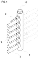
- the transfer unit illustrated in the figure comprises a column 1 on which are fixed several gripping members 3 arranged in the same vertical plane.
- Each gripping member 3 comprises a slot (not shown) through which a vacuum is exerted.
- This mechanism makes it possible to fix, respectively detach, a skirt 4 to the gripping member 3.
- the figure 1 also illustrates the position of the grippers 3 before (solid lines) and after (tiled lines) the 180 ° rotation of the column 1.
- the figure 2 illustrates the movement performed by the skirts 4 about an axis 6 arranged perpendicular to the axis 8 of the column 1.
- the vertical arrow 7 schematically represents the direction of movement of a neighboring element, eg a conveyor equipped with skirts grips.
- the tangential speed of the skirts is substantially identical to the speed of movement of the neighboring element, which allows easy transfer skirts to the neighboring system. Indeed, at the time of transfer, the relative speed between the transfer unit according to the invention and the neighboring element is zero.
- the figure 3 shows a control shaft 2 which ensures the rotation of the gripping members 3 by means of bevel gears 5, the latter being themselves coupled to a rod which merges with the axis 6 which is perpendicular to the axis 8 of column 1.
- This coupling between the two axes 8,6 has the effect of synchronizing the rotational speeds of the two axes.
- the skirts 4 rotate around the axis 6 which is perpendicular to the axis 8 of the column 1.
- the driving of the aforesaid elements can be carried out in different ways, eg by means of a gear, rods or belts.
- figure 4 shows three angular positions different from the directions of a skirt during its rotation about the axis 8 of the column 1.
- the column is not necessarily arranged in a vertical direction. Its section may be of any shape, polygonal or circular. The number and the distribution of the skirts gripping members can also be any. Other coupling systems between the axes of rotation can be used.
- the axis of rotation of the gripping members 3, is not necessarily perpendicular to the axis of symmetry 8 of the column 1 but may form any angle with respect thereto.
- the axis of symmetry of skirt 9, is not necessarily parallel to the axis of rotation of the gripping members 6 but may form any angle with respect thereto.
- the invention covers any type of transfer unit as defined in the claims.
Landscapes
- Engineering & Computer Science (AREA)
- Mechanical Engineering (AREA)
- Robotics (AREA)
- Specific Conveyance Elements (AREA)
- Manipulator (AREA)
Description
- La présente invention se situe dans le domaine des corps tubulaires.
- Elle peut avantageusement être utilisées avec des emballages en forme de tube qui comprennent une épaule et une jupe.
- L'invention concerne plus précisément le transfert de corps tubulaires dans une installation d'assemblage.
- Le plus souvent, les installations d'assemblage de composants de tubes comprennent une première unité qui prépare des jupes. Les jupes sont ensuite acheminées sur un convoyeur linéaire et transitent par un ou plusieurs systèmes de transfert qui modifient leur orientation, p.ex. de 90°. Une fois cette opération effectuée, on fixe les épaules sur une extrémité des jupes.
- Le document brevet
EP 0 175 642 décrit un système de transfert où le changement d'orientation est réalisé par une roue en forme de tronc de cône qui saisit les jupes. La roue est disposée de telle manière à ce que lors de sa rotation, les jupes subissent un changement d'orientation pouvant atteindre 90°. - Le brevet américain
US 6,221,189 B1 décrit également un dispositif d'assemblage comprenant une unité de transfert de corps tubulaires. selon le préambule de la revendication 1. - Les installations précitées, outre leur relative grande taille, ne permettent pas de traiter un nombre élevé de tubes par unité de temps. Par « nombre élevé », on entend quelques centaines par minute. Ceci résulte notamment du fait que l'on doive changer l'orientation des jupes.
- Afin de remédier aux problèmes exposés ci-dessus, la demanderesse a développé un dispositif permettant de travailler à une cadence de production plus élevée. Voir à cet effet la demande de brevet
EP 1 472 062 A1 . - Bien que ce dispositif constitue une amélioration par rapport aux autres dispositifs de l'état de la technique, il subsiste un besoin d'atteindre des cadences de production de tubes encore plus élevées, typiquement de l'ordre de 500 tubes/min.
- La présente invention vise notamment à remédier aux problèmes précités.
- Elle concerne une unité de transfert de corps tubulaires pour installation d'assemblage; selon la revendication 1, ladite unité de transfert comprenant plusieurs organes de saisie de corps tubulaires qui sont disposés selon un même plan vertical et comprenant un élément en forme de colonne montée rotative autour de son axe de symétrie, ledit organe de saisie de corps tubulaires étant fixé sur la colonne et se dirigeant selon une direction de préférence perpendiculaire à l'axe de la colonne, caractérisé par le fait que ledit organe de saisie est par ailleurs monté rotatif autour d'un axe dirigé perpendiculairement à l'axe de la colonne de sorte que le mouvement d'un corps tubulaire retenu par ledit organe de saisie résulte de la combinaison de deux mouvements, à savoir de la rotation de la colonne et de la rotation dudit organe de saisie.
- Avantageusement, l'organe de saisie de corps tubulaires est monté rotatif autour d'un axe dirigé perpendiculairement à l'axe de la colonne.
- De préférence, cet axe est parallèle et distinct de l'axe de symétrie d'un corps tubulaire qui serait fixé à l'organe de saisie. De la sorte, un corps tubulaire peut effectuer un mouvement circulaire autour de cet axe.
- Selon une variante de l'invention, cet axe est entraîné par des moyens appropriés.
- La colonne est également entraînée en rotation. Avantageusement, les moyens d'entraînement rotatif de la colonne sont couplés aux moyens d'entraînement rotatif dudit axe.
- Selon une variante de l'invention, le ou les organes de saisie de corps tubulaires comprennent des moyens d'aspiration qui sont adaptés pour induire un vide, donc une fixation, sur une portion de la paroi latérale des corps tubulaires.
- Alternativement, les corps tubulaires peuvent être saisies par des pinces.
- Afin d'assurer un transfert entre l'unité de transfert selon l'invention et un dispositif voisin devant saisir des corps tubulaires, on impartit une vitesse tangentielle aux corps tubulaires qui est sensiblement identique à la vitesse du dispositif voisin.
- La présente invention permet donc de saisir un corps tubulaire dans une position et de le déposer dans une autre position.
- Le corps tubulaire peut être une jupe, avec ou sans épaule, une bouteille ou plus généralement tout élément cylindrique creux. A noter par ailleurs que la section du corps tubulaire n'est pas nécessairement cylindrique. Elle peut être ovale ou polygonale.
- Les corps tubulaires peuvent être initialement saisis à partir d'un dispositif statique ou mobile.
Idem pour le transfert vers un autre dispositif après le passage dans l'unité de transfert selon l'invention. - L'unité de transfert selon l'invention peut être intégrée dans une installation d'assemblage de composants de corps tubulaires qui peut traiter simultanément plusieurs composants de corps tubulaires.
- L'unité de transfert selon l'invention permet donc d'impartir aux corps tubulaires qu'elle entraîne un mouvement et une trajectoire qui résulte de la combinaison du mouvement induit par la rotation de la colonne et du mouvement induit par la rotation de l'organe de saisie.
- Grâce à cette configuration, divers mouvements et trajectoires peuvent être constitués pour un corps tubulaire qui transite par l'unité de transfert selon l'invention. A titre d'exemple, il est possible de saisir initialement des corps tubulaires en un lieu fixe puis, consécutivement à leur passage dans l'unité de transfert, de les déposer en un lieu en mouvement, p.ex. sur l'extrémité du bras d'un autre dispositif en mouvement.
- L'invention concerne également l'utilisation d'une unité de transfert selon la revendication 6.
- L'invention sera mieux comprise ci-après au moyen d'une description détaillée et d'exemples non-limitatifs illustrés par des figures.
-
- La
figure 1 représente une vue en perspective d'un exemple de colonne de transfert selon l'invention. - La
figure 2 représente la colonne de lafigure 1 vue de face. - La
figure 3 représente l'intérieur de la colonne. - La
figure 4 illustre la colonne vue de dessus. -
- 1. Colonne
- 2. Arbre de commande
- 3. Organe de saisie
- 4. Jupe
- 5. Engrenage conique
- 6. Axe de rotation des organes de saisie
- 7. Sens de déplacement
- 8. Axe de symétrie de la colonne
- 9. Axe de symétrie de jupe
- L'unité de transfert illustrée sur la figure comprend une colonne 1 sur laquelle sont fixés plusieurs organes de saisie 3 disposés selon un même plan vertical. Chaque organe de saisie 3 comporte une fente (non-illustrée) au travers de laquelle un vide est exercé. Ce mécanisme permet de fixer, respectivement détacher, une jupe 4 à l'organe de saisie 3.
Lafigure 1 illustre également la position des organes de saisie 3 avant (traits pleins) et après (traits tillés) la rotation de 180° de la colonne 1. - La
figure 2 illustre le mouvement effectué par les jupes 4 autour d'un axe 6 disposés perpendiculaire à l'axe 8 de la colonne 1. La flèche verticale 7 représente de façon schématique le sens de déplacement d'un élément voisin, p.ex. un convoyeur doté d'organes de saisie de jupes. De préférence, la vitesse tangentielle des jupes est sensiblement identique à la vitesse de déplacement de l'élément voisin, ce qui permet un transfert aisé des jupes vers le système voisin. En effet, au moment du transfert, la vitesse relative entre l'unité de transfert selon l'invention et l'élément voisin est nulle. - La
figure 3 montre un arbre de commande 2 qui assure la rotation des organes de saisies 3 par l'intermédiaire d'engrenages coniques 5, ces derniers étant eux-mêmes couplés à une tige qui se confond avec l'axe 6 qui est perpendiculaire à l'axe 8 de la colonne 1. Ce couplage entre les deux axes 8,6 a pour conséquence de synchroniser les vitesses de rotation des deux axes. Exprimé différemment, lorsque l'arbre de commande 2 tourne, les jupes 4 tournent autour de l'axe 6 qui est perpendiculaire à l'axe 8 de la colonne 1. - L'entraînement des éléments précités peut être réalisé de différentes manières, p.ex. au moyen d'un engrenage, de tringles ou de courroies.
- Enfin, la
figure 4 montre trois positions angulaires différentes des directions d'une jupe lors de sa rotation autour de l'axe 8 de la colonne 1. - Il va de soi que l'invention ne se limite pas aux exemples illustrés décrits précédemment.
La colonne n'est pas nécessairement disposée selon une direction verticale.
Sa section peut être de forme quelconque, polygonale ou circulaire.
Le nombre et la distribution des organes de saisie des jupes peut également être quelconque.
D'autres systèmes de couplage entre les axes de rotation peuvent être utilisés. - L'axe de rotation des organes de saisies 3, n'est pas forcément perpendiculaire à l'axe de symétrie 8 de la colonne 1 mais peut former un angle quelconque par rapport à celui-ci.
- L'axe de symétrie de jupe 9, n'est pas forcément parallèle à l'axe de rotation des organes de saisies 6 mais peut former un angle quelconque par rapport à celui-ci.
- Plus généralement, l'invention couvre n'importe quel type d'unité de transfert telle que définie dans les revendications.
Claims (6)
- Unité de transfert de corps tubulaires (4) pour installation d'assemblage; ladite unité de transfert comprenant plusieurs organes de saisie (3) de corps tubulaires (4) qui sont disposés selon un même plan vertical et comprenant un élément en forme de colonne (1) montée rotative autour de son axe de symétrie (8), ledit organe de saisie (3) de corps tubulaires (4) étant fixé sur la colonne (1) et se dirigeant selon une direction (9) de préférence perpendiculaire à l'axe de la colonne (1), caractérisé par le fait que ledit organe de saisie (3) est par ailleurs monté rotatif autour d'un axe (6) dirigé perpendiculairement à l'axe de la colonne (1), de sorte que le mouvement d'un corps tubulaire (4) retenu par ledit organe de saisie (3) résulte de la combinaison de deux mouvements, à savoir de la rotation de la colonne (1) et de la rotation dudit organe de saisie (3).
- Unité de transfert selon la revendication 1 caractérisée en ce que ledit axe (6) est parallèle à l'axe de symétrie (9) d'un corps tubulaire (4) qui serait fixé à l'organe de saisie (3).
- Unité de transfert selon la revendication 2 comprenant des moyens d'entraînement (2,5) dudit axe (6).
- Unité de transfert selon la revendication 3 comprenant des moyens d'entraînement rotatif (2) de la colonne (1) qui sont couplés aux moyens d'entraînement (2,5) dudit axe (6).
- Unité de transfert selon l'une quelconque des revendications précédentes caractérisé en ce que le ou les organes de saisie (3) de corps tubulaires (4) comprennent des moyens d'aspiration.
- Utilisation d'une unité de transfert selon la revendication 4 ou 5 caractérisée en ce que la vitesse tangentielle d'un corps tubulaire (4) en rotation autour dudit axe (6) est sensiblement identique à la vitesse d'un dispositif voisin qui devrait saisir les corps tubulaires (4) de l'unité de transfert.
Priority Applications (1)
| Application Number | Priority Date | Filing Date | Title |
|---|---|---|---|
| EP07735916.4A EP2024152B1 (fr) | 2006-06-02 | 2007-05-15 | Unite de transfert de corps tubulaires |
Applications Claiming Priority (3)
| Application Number | Priority Date | Filing Date | Title |
|---|---|---|---|
| EP06114923A EP1862284A1 (fr) | 2006-06-02 | 2006-06-02 | Unite de transfert de corps tubulairs |
| EP07735916.4A EP2024152B1 (fr) | 2006-06-02 | 2007-05-15 | Unite de transfert de corps tubulaires |
| PCT/IB2007/051847 WO2007141683A1 (fr) | 2006-06-02 | 2007-05-15 | Unite de transfert de corps tubulaires |
Publications (2)
| Publication Number | Publication Date |
|---|---|
| EP2024152A1 EP2024152A1 (fr) | 2009-02-18 |
| EP2024152B1 true EP2024152B1 (fr) | 2016-08-17 |
Family
ID=37434234
Family Applications (2)
| Application Number | Title | Priority Date | Filing Date |
|---|---|---|---|
| EP06114923A Withdrawn EP1862284A1 (fr) | 2006-06-02 | 2006-06-02 | Unite de transfert de corps tubulairs |
| EP07735916.4A Active EP2024152B1 (fr) | 2006-06-02 | 2007-05-15 | Unite de transfert de corps tubulaires |
Family Applications Before (1)
| Application Number | Title | Priority Date | Filing Date |
|---|---|---|---|
| EP06114923A Withdrawn EP1862284A1 (fr) | 2006-06-02 | 2006-06-02 | Unite de transfert de corps tubulairs |
Country Status (4)
| Country | Link |
|---|---|
| EP (2) | EP1862284A1 (fr) |
| CN (1) | CN101454133B (fr) |
| ES (1) | ES2595098T3 (fr) |
| WO (1) | WO2007141683A1 (fr) |
Families Citing this family (2)
| Publication number | Priority date | Publication date | Assignee | Title |
|---|---|---|---|---|
| DE102010009826A1 (de) * | 2010-03-02 | 2011-09-08 | Iwk Verpackungstechnik Gmbh | Tuben-Übergabevorrichtung |
| EP3414070A1 (fr) * | 2016-02-10 | 2018-12-19 | Inovia Technologies SA | Unité d'assemblage et/ou de traitements de composants |
Family Cites Families (6)
| Publication number | Priority date | Publication date | Assignee | Title |
|---|---|---|---|---|
| DE3580080D1 (de) | 1984-09-18 | 1990-11-15 | Obrist & Co Ag H | Verfahren und vorrichtung zum herstellen eines formkoerpers aus kunststoffmaterial. |
| US5225132A (en) * | 1991-08-09 | 1993-07-06 | Farina Richard C | Process and apparatus for producing a molded body of plastic material |
| US6221189B1 (en) * | 1998-11-25 | 2001-04-24 | Thatcher Tubes Llc | Method for manufacturing thermoplastic tubes |
| FR2822101B1 (fr) * | 2001-03-19 | 2006-12-08 | Cebal | Atelier de fabrication de tubes souples en matiere plastique avec moulage de la tete sur la jupe effectuee par des outillages en mouvement continu |
| ES2226599T3 (es) | 2001-11-30 | 2008-05-01 | Aisapack Holding Sa | Instalacion de ensamblaje de componentes de tubos. |
| DE10237839B3 (de) * | 2002-08-19 | 2004-01-22 | Aisa Automation Industrielle S.A. | Anlage zum Herstellen und Verpacken von Tuben |
-
2006
- 2006-06-02 EP EP06114923A patent/EP1862284A1/fr not_active Withdrawn
-
2007
- 2007-05-15 ES ES07735916.4T patent/ES2595098T3/es active Active
- 2007-05-15 CN CN200780019183XA patent/CN101454133B/zh not_active Expired - Fee Related
- 2007-05-15 WO PCT/IB2007/051847 patent/WO2007141683A1/fr not_active Ceased
- 2007-05-15 EP EP07735916.4A patent/EP2024152B1/fr active Active
Also Published As
| Publication number | Publication date |
|---|---|
| WO2007141683A1 (fr) | 2007-12-13 |
| HK1131589A1 (en) | 2010-01-29 |
| EP1862284A1 (fr) | 2007-12-05 |
| EP2024152A1 (fr) | 2009-02-18 |
| CN101454133B (zh) | 2011-10-19 |
| ES2595098T3 (es) | 2016-12-27 |
| CN101454133A (zh) | 2009-06-10 |
Similar Documents
| Publication | Publication Date | Title |
|---|---|---|
| EP1723060B1 (fr) | Dispositif de convoyage comportant un bras de transfert | |
| CA2961308C (fr) | Dispositif de transfert de pieces en defilement | |
| EP1849541B1 (fr) | Installation de chargement séquentiel de barres de matériau dans une machine d'usinage | |
| EP2361713B1 (fr) | Dispositif de gestion des électrodes pour machines d'usinage par électroérosion | |
| EP2178778A2 (fr) | Dispositif de convoyage de recipients divisant un flux principal de recipients en une pluralite de flux secondaires | |
| FR2956377A1 (fr) | Dispositif de commande par cremalleres de la position angulaire d'aubes pivotantes de turbomachine | |
| FR2726543A1 (fr) | Ensemble a etoile centrale a changement rapide pour une machine de bouchage | |
| EP3909743B1 (fr) | Installation de transport de preformes equipee d'un dispositif d'indexage angulaire de tournettes | |
| FR3056199A3 (fr) | Unite de transfert pour transferer des articles entre deux lignes disposees angulairement l'une par rapport a l'autre | |
| FR2574384A1 (fr) | Dispositif pour transferer des objets en forme de barreaux, notamment dans la fabrication de cigarettes | |
| WO2007141683A1 (fr) | Unite de transfert de corps tubulaires | |
| FR3023577B1 (fr) | Procede de forage d'un sol a l'aide d'un bras robotise | |
| EP4126721A1 (fr) | Dispositif de transfert d'articles presentant des dimensions transversales variees et installation comprenant de tels dispositifs | |
| EP2741861A1 (fr) | Dispositif de décapage cryogénique de surfaces non planes, en particulier de l'intérieur d'un tube | |
| FR2573006A1 (fr) | Machine a imprimer | |
| WO2016001333A1 (fr) | Installation de transport de recipients | |
| EP1775126A2 (fr) | Dispositif de transfert d'un objet pour machine d'impression, machine d'impression et procédé de transfert | |
| FR2694537A1 (fr) | Dispositif d'accrochage d'une turbomachine sur une structure d'aéronef. | |
| WO2005044510A2 (fr) | Dispositif d'aspiration associe a l'outil d'une machine-outil d'usinage | |
| FR3076551A1 (fr) | Dispositif d'application automatique d'une fermeture comportant un filetage interieur sur un recipient pourvu d'un filetage exterieur correspondant, et procede d'application a l'aide dudit dispositif | |
| EP3164347B1 (fr) | Installation de transport de récipients | |
| FR2522294A1 (fr) | Dispositif de chargement et dechargement de pieces pour une machine-outil telle qu'une machine de tournage | |
| EP3366520B1 (fr) | Porte-vélo | |
| FR2704537A1 (fr) | Mécanisme pour enrouler et/ou dévider une conduite flexible et installation pour nettoyer des objets allongés creux, comportant ledit mécanisme. | |
| EP4717419A1 (fr) | Dispositif prehenseur |
Legal Events
| Date | Code | Title | Description |
|---|---|---|---|
| PUAI | Public reference made under article 153(3) epc to a published international application that has entered the european phase |
Free format text: ORIGINAL CODE: 0009012 |
|
| 17P | Request for examination filed |
Effective date: 20081219 |
|
| AK | Designated contracting states |
Kind code of ref document: A1 Designated state(s): AT BE BG CH CY CZ DE DK EE ES FI FR GB GR HU IE IS IT LI LT LU LV MC MT NL PL PT RO SE SI SK TR |
|
| AX | Request for extension of the european patent |
Extension state: AL BA HR MK RS |
|
| RIN1 | Information on inventor provided before grant (corrected) |
Inventor name: VOIGTMANN, JEAN-PIERRE Inventor name: STAHL, CHRISTOPHE |
|
| RIN1 | Information on inventor provided before grant (corrected) |
Inventor name: STAHL, CHRISTOPHE Inventor name: VOIGTMANN, JEAN-PIERRE |
|
| 17Q | First examination report despatched |
Effective date: 20100209 |
|
| DAX | Request for extension of the european patent (deleted) | ||
| GRAP | Despatch of communication of intention to grant a patent |
Free format text: ORIGINAL CODE: EPIDOSNIGR1 |
|
| INTG | Intention to grant announced |
Effective date: 20160310 |
|
| GRAS | Grant fee paid |
Free format text: ORIGINAL CODE: EPIDOSNIGR3 |
|
| GRAA | (expected) grant |
Free format text: ORIGINAL CODE: 0009210 |
|
| AK | Designated contracting states |
Kind code of ref document: B1 Designated state(s): AT BE BG CH CY CZ DE DK EE ES FI FR GB GR HU IE IS IT LI LT LU LV MC MT NL PL PT RO SE SI SK TR |
|
| REG | Reference to a national code |
Ref country code: GB Ref legal event code: FG4D Free format text: NOT ENGLISH |
|
| REG | Reference to a national code |
Ref country code: CH Ref legal event code: EP |
|
| REG | Reference to a national code |
Ref country code: IE Ref legal event code: FG4D Free format text: LANGUAGE OF EP DOCUMENT: FRENCH |
|
| REG | Reference to a national code |
Ref country code: AT Ref legal event code: REF Ref document number: 820618 Country of ref document: AT Kind code of ref document: T Effective date: 20160915 |
|
| REG | Reference to a national code |
Ref country code: DE Ref legal event code: R096 Ref document number: 602007047498 Country of ref document: DE |
|
| REG | Reference to a national code |
Ref country code: NL Ref legal event code: MP Effective date: 20160817 |
|
| REG | Reference to a national code |
Ref country code: LT Ref legal event code: MG4D Ref country code: ES Ref legal event code: FG2A Ref document number: 2595098 Country of ref document: ES Kind code of ref document: T3 Effective date: 20161227 |
|
| REG | Reference to a national code |
Ref country code: AT Ref legal event code: MK05 Ref document number: 820618 Country of ref document: AT Kind code of ref document: T Effective date: 20160817 |
|
| PG25 | Lapsed in a contracting state [announced via postgrant information from national office to epo] |
Ref country code: FI Free format text: LAPSE BECAUSE OF FAILURE TO SUBMIT A TRANSLATION OF THE DESCRIPTION OR TO PAY THE FEE WITHIN THE PRESCRIBED TIME-LIMIT Effective date: 20160817 Ref country code: NL Free format text: LAPSE BECAUSE OF FAILURE TO SUBMIT A TRANSLATION OF THE DESCRIPTION OR TO PAY THE FEE WITHIN THE PRESCRIBED TIME-LIMIT Effective date: 20160817 Ref country code: LT Free format text: LAPSE BECAUSE OF FAILURE TO SUBMIT A TRANSLATION OF THE DESCRIPTION OR TO PAY THE FEE WITHIN THE PRESCRIBED TIME-LIMIT Effective date: 20160817 |
|
| PG25 | Lapsed in a contracting state [announced via postgrant information from national office to epo] |
Ref country code: GR Free format text: LAPSE BECAUSE OF FAILURE TO SUBMIT A TRANSLATION OF THE DESCRIPTION OR TO PAY THE FEE WITHIN THE PRESCRIBED TIME-LIMIT Effective date: 20161118 Ref country code: PL Free format text: LAPSE BECAUSE OF FAILURE TO SUBMIT A TRANSLATION OF THE DESCRIPTION OR TO PAY THE FEE WITHIN THE PRESCRIBED TIME-LIMIT Effective date: 20160817 Ref country code: LV Free format text: LAPSE BECAUSE OF FAILURE TO SUBMIT A TRANSLATION OF THE DESCRIPTION OR TO PAY THE FEE WITHIN THE PRESCRIBED TIME-LIMIT Effective date: 20160817 Ref country code: SE Free format text: LAPSE BECAUSE OF FAILURE TO SUBMIT A TRANSLATION OF THE DESCRIPTION OR TO PAY THE FEE WITHIN THE PRESCRIBED TIME-LIMIT Effective date: 20160817 Ref country code: AT Free format text: LAPSE BECAUSE OF FAILURE TO SUBMIT A TRANSLATION OF THE DESCRIPTION OR TO PAY THE FEE WITHIN THE PRESCRIBED TIME-LIMIT Effective date: 20160817 Ref country code: PT Free format text: LAPSE BECAUSE OF FAILURE TO SUBMIT A TRANSLATION OF THE DESCRIPTION OR TO PAY THE FEE WITHIN THE PRESCRIBED TIME-LIMIT Effective date: 20161219 |
|
| PG25 | Lapsed in a contracting state [announced via postgrant information from national office to epo] |
Ref country code: RO Free format text: LAPSE BECAUSE OF FAILURE TO SUBMIT A TRANSLATION OF THE DESCRIPTION OR TO PAY THE FEE WITHIN THE PRESCRIBED TIME-LIMIT Effective date: 20160817 Ref country code: EE Free format text: LAPSE BECAUSE OF FAILURE TO SUBMIT A TRANSLATION OF THE DESCRIPTION OR TO PAY THE FEE WITHIN THE PRESCRIBED TIME-LIMIT Effective date: 20160817 |
|
| REG | Reference to a national code |
Ref country code: DE Ref legal event code: R097 Ref document number: 602007047498 Country of ref document: DE |
|
| REG | Reference to a national code |
Ref country code: FR Ref legal event code: PLFP Year of fee payment: 11 |
|
| PG25 | Lapsed in a contracting state [announced via postgrant information from national office to epo] |
Ref country code: CZ Free format text: LAPSE BECAUSE OF FAILURE TO SUBMIT A TRANSLATION OF THE DESCRIPTION OR TO PAY THE FEE WITHIN THE PRESCRIBED TIME-LIMIT Effective date: 20160817 Ref country code: DK Free format text: LAPSE BECAUSE OF FAILURE TO SUBMIT A TRANSLATION OF THE DESCRIPTION OR TO PAY THE FEE WITHIN THE PRESCRIBED TIME-LIMIT Effective date: 20160817 Ref country code: SK Free format text: LAPSE BECAUSE OF FAILURE TO SUBMIT A TRANSLATION OF THE DESCRIPTION OR TO PAY THE FEE WITHIN THE PRESCRIBED TIME-LIMIT Effective date: 20160817 |
|
| PLBE | No opposition filed within time limit |
Free format text: ORIGINAL CODE: 0009261 |
|
| STAA | Information on the status of an ep patent application or granted ep patent |
Free format text: STATUS: NO OPPOSITION FILED WITHIN TIME LIMIT |
|
| 26N | No opposition filed |
Effective date: 20170518 |
|
| PGFP | Annual fee paid to national office [announced via postgrant information from national office to epo] |
Ref country code: FR Payment date: 20170523 Year of fee payment: 11 Ref country code: GB Payment date: 20170519 Year of fee payment: 11 |
|
| PG25 | Lapsed in a contracting state [announced via postgrant information from national office to epo] |
Ref country code: LU Free format text: LAPSE BECAUSE OF NON-PAYMENT OF DUE FEES Effective date: 20170531 Ref country code: SI Free format text: LAPSE BECAUSE OF FAILURE TO SUBMIT A TRANSLATION OF THE DESCRIPTION OR TO PAY THE FEE WITHIN THE PRESCRIBED TIME-LIMIT Effective date: 20160817 |
|
| PGFP | Annual fee paid to national office [announced via postgrant information from national office to epo] |
Ref country code: IT Payment date: 20170526 Year of fee payment: 11 |
|
| PG25 | Lapsed in a contracting state [announced via postgrant information from national office to epo] |
Ref country code: MC Free format text: LAPSE BECAUSE OF FAILURE TO SUBMIT A TRANSLATION OF THE DESCRIPTION OR TO PAY THE FEE WITHIN THE PRESCRIBED TIME-LIMIT Effective date: 20160817 |
|
| REG | Reference to a national code |
Ref country code: IE Ref legal event code: MM4A |
|
| PG25 | Lapsed in a contracting state [announced via postgrant information from national office to epo] |
Ref country code: LU Free format text: LAPSE BECAUSE OF NON-PAYMENT OF DUE FEES Effective date: 20170515 |
|
| REG | Reference to a national code |
Ref country code: BE Ref legal event code: MM Effective date: 20170531 |
|
| PG25 | Lapsed in a contracting state [announced via postgrant information from national office to epo] |
Ref country code: IE Free format text: LAPSE BECAUSE OF NON-PAYMENT OF DUE FEES Effective date: 20170515 |
|
| REG | Reference to a national code |
Ref country code: CH Ref legal event code: NV Representative=s name: ANDRE ROLAND S.A., CH |
|
| REG | Reference to a national code |
Ref country code: ES Ref legal event code: FD2A Effective date: 20180704 |
|
| PG25 | Lapsed in a contracting state [announced via postgrant information from national office to epo] |
Ref country code: ES Free format text: LAPSE BECAUSE OF NON-PAYMENT OF DUE FEES Effective date: 20170516 |
|
| PGFP | Annual fee paid to national office [announced via postgrant information from national office to epo] |
Ref country code: DE Payment date: 20180522 Year of fee payment: 12 |
|
| PG25 | Lapsed in a contracting state [announced via postgrant information from national office to epo] |
Ref country code: BE Free format text: LAPSE BECAUSE OF NON-PAYMENT OF DUE FEES Effective date: 20170531 |
|
| PG25 | Lapsed in a contracting state [announced via postgrant information from national office to epo] |
Ref country code: MT Free format text: LAPSE BECAUSE OF FAILURE TO SUBMIT A TRANSLATION OF THE DESCRIPTION OR TO PAY THE FEE WITHIN THE PRESCRIBED TIME-LIMIT Effective date: 20160817 |
|
| GBPC | Gb: european patent ceased through non-payment of renewal fee |
Effective date: 20180515 |
|
| PG25 | Lapsed in a contracting state [announced via postgrant information from national office to epo] |
Ref country code: IT Free format text: LAPSE BECAUSE OF NON-PAYMENT OF DUE FEES Effective date: 20180515 Ref country code: FR Free format text: LAPSE BECAUSE OF NON-PAYMENT OF DUE FEES Effective date: 20180531 Ref country code: GB Free format text: LAPSE BECAUSE OF NON-PAYMENT OF DUE FEES Effective date: 20180515 |
|
| PG25 | Lapsed in a contracting state [announced via postgrant information from national office to epo] |
Ref country code: HU Free format text: LAPSE BECAUSE OF FAILURE TO SUBMIT A TRANSLATION OF THE DESCRIPTION OR TO PAY THE FEE WITHIN THE PRESCRIBED TIME-LIMIT; INVALID AB INITIO Effective date: 20070515 |
|
| PG25 | Lapsed in a contracting state [announced via postgrant information from national office to epo] |
Ref country code: CY Free format text: LAPSE BECAUSE OF NON-PAYMENT OF DUE FEES Effective date: 20160817 |
|
| REG | Reference to a national code |
Ref country code: DE Ref legal event code: R119 Ref document number: 602007047498 Country of ref document: DE |
|
| PG25 | Lapsed in a contracting state [announced via postgrant information from national office to epo] |
Ref country code: TR Free format text: LAPSE BECAUSE OF FAILURE TO SUBMIT A TRANSLATION OF THE DESCRIPTION OR TO PAY THE FEE WITHIN THE PRESCRIBED TIME-LIMIT Effective date: 20160817 |
|
| PG25 | Lapsed in a contracting state [announced via postgrant information from national office to epo] |
Ref country code: DE Free format text: LAPSE BECAUSE OF NON-PAYMENT OF DUE FEES Effective date: 20191203 |
|
| PG25 | Lapsed in a contracting state [announced via postgrant information from national office to epo] |
Ref country code: IS Free format text: LAPSE BECAUSE OF FAILURE TO SUBMIT A TRANSLATION OF THE DESCRIPTION OR TO PAY THE FEE WITHIN THE PRESCRIBED TIME-LIMIT Effective date: 20161217 |
|
| PGFP | Annual fee paid to national office [announced via postgrant information from national office to epo] |
Ref country code: CH Payment date: 20230605 Year of fee payment: 17 Ref country code: BG Payment date: 20230526 Year of fee payment: 17 |
|
| REG | Reference to a national code |
Ref country code: CH Ref legal event code: PL |
|
| PG25 | Lapsed in a contracting state [announced via postgrant information from national office to epo] |
Ref country code: BG Free format text: LAPSE BECAUSE OF NON-PAYMENT OF DUE FEES Effective date: 20240515 |
|
| PG25 | Lapsed in a contracting state [announced via postgrant information from national office to epo] |
Ref country code: BG Free format text: LAPSE BECAUSE OF NON-PAYMENT OF DUE FEES Effective date: 20240515 Ref country code: CH Free format text: LAPSE BECAUSE OF NON-PAYMENT OF DUE FEES Effective date: 20240531 |