EP2024228B1 - Rumpfstruktur - Google Patents
Rumpfstruktur Download PDFInfo
- Publication number
- EP2024228B1 EP2024228B1 EP07729698A EP07729698A EP2024228B1 EP 2024228 B1 EP2024228 B1 EP 2024228B1 EP 07729698 A EP07729698 A EP 07729698A EP 07729698 A EP07729698 A EP 07729698A EP 2024228 B1 EP2024228 B1 EP 2024228B1
- Authority
- EP
- European Patent Office
- Prior art keywords
- grid
- fuselage
- shell
- window
- gap
- Prior art date
- Legal status (The legal status is an assumption and is not a legal conclusion. Google has not performed a legal analysis and makes no representation as to the accuracy of the status listed.)
- Not-in-force
Links
Images



Classifications
-
- B—PERFORMING OPERATIONS; TRANSPORTING
- B64—AIRCRAFT; AVIATION; COSMONAUTICS
- B64C—AEROPLANES; HELICOPTERS
- B64C1/00—Fuselages; Constructional features common to fuselages, wings, stabilising surfaces or the like
- B64C1/06—Frames; Stringers; Longerons ; Fuselage sections
- B64C1/068—Fuselage sections
-
- B—PERFORMING OPERATIONS; TRANSPORTING
- B64—AIRCRAFT; AVIATION; COSMONAUTICS
- B64C—AEROPLANES; HELICOPTERS
- B64C1/00—Fuselages; Constructional features common to fuselages, wings, stabilising surfaces or the like
- B64C1/06—Frames; Stringers; Longerons ; Fuselage sections
- B64C1/12—Construction or attachment of skin panels
-
- B—PERFORMING OPERATIONS; TRANSPORTING
- B64—AIRCRAFT; AVIATION; COSMONAUTICS
- B64C—AEROPLANES; HELICOPTERS
- B64C1/00—Fuselages; Constructional features common to fuselages, wings, stabilising surfaces or the like
- B64C1/14—Windows; Doors; Hatch covers or access panels; Surrounding frame structures; Canopies; Windscreens accessories therefor, e.g. pressure sensors, water deflectors, hinges, seals, handles, latches, windscreen wipers
- B64C1/1476—Canopies; Windscreens or similar transparent elements
- B64C1/1492—Structure and mounting of the transparent elements in the window or windscreen
Definitions
- the present invention relates to a fuselage structure, in particular of an aircraft or spacecraft.
- Aircraft fuselages nowadays are generally manufactured in an aluminium shell construction.
- window openings are milled into the shells, which are assembled in a later manufacturing step to form a section of the aircraft fuselage.
- the shells can be either of single-walled or double-walled or multi-walled design with inner and outer shells being used, and with sandwich core material arranged between the inner and outer shells.
- the arrangement pf the window openings in the shells is generally selected in such a manner that, in the finished aircraft fuselage, they are located approximately at eye level of people sitting in the passenger compartment.
- the window openings are arranged along one or more window bands running laterally along the aircraft fuselage.
- window openings After the window openings have been milled, they are each reinforced by an aluminium window frame.
- the window panes are subsequently placed into the aluminium window frames.
- a further constructional example can be found in FR 1497214 . It is therefore the object of the present invention to provide a fuselage structure which ensure a light region without the use of solid window frames.
- the fuselage structure in particular of an aircraft or spacecraft, has an inner shell arrangement, which has a lower inner shell and an upper inner shell, the upper inner shell being spaced apart at least in some sections from the lower inner shell by a first gap in order to form a window region; and a window band which is arranged at least in the region of the first gap and has a pane device which comprises a grid structure which absorbs fuselage forces.
- the fuselage structure furthermore has an outer shell arrangement which has a lower outer shell associated with the lower inner shell and an upper outer shell associated with the upper inner shell, the upper outer shell being spaced apart at least in some sections in the window region from the lower outer shell by a second gap.
- the grid structure extends beyond the window region, which is formed by the first and second gaps, into the shell arrangements and can be fastened to the individual shells of the shell arrangements in order to form a fuselage structure which connects the individual shells to one another and is optimized in terms of force flux. This can be brought about, for example, by means of a suitable adhesive bonding connection or the like. This ensures an optimized transmission of force from the fuselage structure to the lattice structure, even in the region of the window band.
- the present invention therefore has the advantage over the approaches mentioned at the beginning that the grid structure takes over the function of the window frames used in a conventional construction. Consequently, the fuselage structure is strengthened in the region of the window band, and the fuselage forces which occur are deflected around the recessed window regions in the region of the window band.
- a structure which is optimized in terms of force flux in such a manner enables the windows to advantageously turn out to be considerably larger than has generally hitherto been possible.
- the grid structure has individual grid ribs for forming grid meshes, the grid structure being designed to absorb the forces occuring in the fuselage.
- the grid structure is advantageously designed as a lattice grid structure or the like and, in terms of shape configuration, is matched to the shape of the shell arrangement.
- the curvature of the grid structure is advantageously matched to the curvature of the respective shells.
- a lattice grid structure can better transmit forces than other grids, such as, for example, an ISO grid structure.
- the first gap and the second gap are advantageously formed at the same height and, at least in some sections, such that they run in the longitudinal direction of the fuselage structure, in order to form an optimized window region. This ensures an optimum region of view for the occupants, with it being possible for the window region to be configured to be an adequate size on account of the grid structure which absorbs the fuselage forces.
- the first gap and the second gap have, in particular, the same gap width and/or gap lengths, and they are therefore matched to each other in such a manner that an optimum region of view for the occupants is ensured.
- the double pane has at least two individual panes which each end flush with the inner and/or outer shells, can be fastened to the inner and/or outer shells and enclose the grid structure between them. This results in a robust window band structure which deflects the fuselage forces over the window region and permits an optimum view for the occupants out of the vehicle.
- a suitable core material is provided between the inner and outer shells, at least with the exception of the window region.
- Said core material can be fastened to the inner and/or outer shells, for example, likewise by means of a suitable adhesive bonding process or the like.
- window regions can be provided in different regions in, for example, an aircraft, with it being possible for the fuselage structure in this case also to be formed from a plurality of shell sections in the longitudinal direction, for example, or from shells with suitable recesses in the respective window regions.
- the method according to the invention and the fuselage structure according to the invention are used correspondingly for each window band, with, for example, in the case of two window bands, three inner shells, in particular an upper inner shell, a central inner shell and a lower inner shell, being arranged, each spaced apart from one another by the height of the particular window band, and subsequently use being made of a grid-shaped connecting structure which overlaps both window bands, or of two grid-shaped connecting structures,'which each overlap a window band, in order to connect the inner shells, which are spaced apart from one another, to one another.
- three outer shells in particular an upper outer shell, a central outer shell and a lower outer shell, are arranged on the inner shells, each spaced apart from one another on the sandwich core material and the grid-shaped connecting structure by the height of the respective window band before the window panes are arranged on the inside and outside in the region of the window bands.
- the invention is preferably used in a double-shell fuselage construction.
- the main elements of the aircraft fuselage structure i.e. the lower shell and the upper shell
- the window band is designed as a double pane reinforced by means of the grid-shaped connecting structure.
- the connecting structure is then preferably arranged from the inside on the shells which are spaced apart from one another, and therefore the connecting structure spans the gap formed and connects the two shells to each other.
- Window panes which preferably close the gap and end flush with the shells are then arranged on the connecting structure from the outside.
- window panes can likewise additionally be arranged on the connecting structure.
- coverings, insulation materials and the like can also be arranged on the inside of the outer shells.
- the grid-shaped connecting structure takes on the function of the window frames used in a conventional construction.
- the function is a strengthening of the fuselage structure in the region of the window band and a deflection of the force flux around the windows in the region of the window band.
- the present invention has the advantage over the prior art that the grid-shaped connecting structure can be designed with regard to the force flux, and therefore the grid ribs forming the grid-shaped connecting structure run in the direction of the forces which occur in the aircraft fuselage. As a result, the forces which occur are conducted around the windows.
- the grid ribs can comprise either fibre structures, such as, for example, carbon fibres, aramid fibres, glass fibres and the like, or fibre-reinforced structures, such as, for example, fibre-reinforced plastics, fibre-reinforced composite structures, such as, for example, fibre-reinforced metals and fibre-reinforced metal sandwich structures, and metallic structures, such as, for example, metallic struts, bands and the like.
- a further advantage is that the structure which is optimized in terms of force flux enables the windows to turn out to be considerably larger than in a conventional construction. Furthermore, unlike in the conventional construction, the complicated installation of the individual windows and their frames is omitted.
- a particularly advantageous refinement of the invention makes provision for the grid-shaped connecting structure to comprise a lattice grid.
- a lattice grid which is also referred to as an anisogrid structure, is distinguished in that the meshes formed by the grid ribs do not have the same geometrical shapes and dimensions in all of the regions of the lattice grid.
- the grid ribs are oriented primarily with regard to the forces which occur and not with regard to a geometrical structure which can be produced as simply as possible. This may result in irregular geometries of the meshes, at least in parts of the lattice grid, with it also being possible that, in other parts of the lattice grid, regular structures similar to an ISO grid structure occur.
- Lattice grids are therefore more suitable than other grid-shaped structures, such as, for example, ISO grid structures, to transmit forces. Furthermore, lattice grids can be composed of a plurality of different materials which can be selected in accordance with the forces which occur, the dynamic force profile and the expansions required in certain directions.
- An additional advantageous refinement of the invention makes provision for the thickness of the grid-shaped connecting structure and the thickness of the sandwich core material to be essentially identical.
- a grid-shaped connecting structure which is optimized with regard to the force flux in the finished aircraft fuselage structure is premanufactured.
- the length of the grid-shaped connecting structure corresponds approximately to the length of a fuselage section to be produced or to the length of a window region to be provided.
- the width of the grid-shaped connecting structure is preferably greater than the desired height of the window band.
- the meshes of the grid-shaped connecting structure which are formed by the grid ribs, are approximately the size of the individual windows of the window band, at least in the region in which, in a later method step, window panes are arranged on the grid-shaped connecting structure.
- the grid-shaped connecting structure is optimized with regard to the force flux, for example, in such a manner that a numerical simulation, for example a finite-element analysis (FEM), is used to calculate the force flux at least with regard to the magnitude and the direction of the forces occurring in the region of the window band.
- FEM finite-element analysis
- a grid structure is then prepared, which coincides as precisely as possible with the calculated directions of the forces which occur, and has meshes of an adequate size in the region of the window band in order to be able to use said meshes as windows.
- the forces which occur in the prepared grid structure are calculated and the grid ribs which form the grid-shaped connecting structure are dimensioned with regard to dimensions, such as, for example, cross sections and the like, and with regard to the materials to be used.
- the grid-shaped connecting structure is premanufactured on the basis of these sizes.
- Two inner shells an upper inner shell and a lower inner shell, are arranged at a distance corresponding to the height of the window band.
- the inner shells are connected to one another by means of the premanufactured grid-shaped connecting structure. This takes place in such a manner that the grid-shaped connecting structure is connected to the inner shells, for example by adhesive bonding, in a manner overlapping the gap between the inner shells, which corresponds in its width to the height of the window band.
- the grid-shaped connecting structure spans the gap between the inner shells, with the meshes of the grid-shaped connecting structure, which are to serve as windows, coming to lie precisely in the region of the gap.
- a sandwich core material is arranged from the outside on those regions of the inner shells which are not covered by the grid-shaped connecting structure.
- the sandwich core material and the grid-shaped connecting structure preferably have the same thickness perpendicular to the local surface of the inner shells.
- Two outer shells an upper outer shell and a lower outer shell, are arranged on the core material and the overlapping part of the grid-shaped connecting structure at a distance corresponding to the height of the window band in such a manner that the outer shells are spaced apart from one another in the region of the window band and the later window band is covered neither by the inner shells nor by the outer shells.
- window panes are arranged on both sides of that region of the grid-shaped connecting structure which is not covered by the inner and outer shells.
- the window panes end flush with the inner and outer shells both with regard to the dimensions of the window band and with regard to the thickness of the inner and outer shells.
- Fig. 2 illustrates, by way of example, a grid-shaped connecting structure 10 which is premanufactured in a lattice construction.
- the grid-shaped connecting structure 10 comprises, in particular, grid ribs 11 and meshes 12 formed by the grid ribs 11.
- the grid-shaped connecting structure 10 is optimized, with regard to magnitude and direction of the forces which occur, to the force flux occurring in the region of the window band 41 of the aircraft fuselage structure ( Fig. 6a ).
- the grid ribs 11 of the grid-shaped connecting structure 10 are preferably oriented in the direction of the forces to be anticipated.
- the meshes 12 of the grid-shaped connecting structure 10 are dimensioned, at least in the region 13 which comes to lie in the region of the window band, in such a manner that each mesh 14 serves as a window.
- the length L of the grid-shaped connecting structure 10 corresponds to the length S of a fuselage section to be produced.
- the width V of the grid-shaped connecting structure 10 is greater than the height H of the window band 41 ( Fig. 6 ).
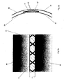
- FIGs 3a and 3b it is apparent how an upper inner shell 21 and a lower inner shell 22 are arranged at a distance with respect to each other that corresponds to the desired height of the window band.
- the two inner shells 20 here are positioned on an apparatus in such a manner that a gap 23, the width B of which corresponds to the height H of the window band 41 ( Fig. 6 ), remains free.
- the meshes 14 which serve as viewing regions come to lie in the region of the gap 23.
- Figs 4a and 4b illustrate a means of fixing, by way of example, the grid-shaped connecting structure 10 on the inner shells 20.
- the grid-shaped connecting structure 10 overlaps the gap 23 between the inner shells 20.
- the grid-shaped connecting structure 10 overlaps the upper inner shell 21 and the lower inner shell 22.
- a sandwich core material is arranged from the inside to the outside on those regions of the inner shells which are not covered by the grid-shaped connecting structure takes place in accordance with known procedures and is not illustrated in a separate figure.
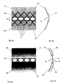
- FIGs 5a and 5b how two outer shells 30, an upper outer shell 31 and a lower outer shell 32, are arranged on the core material (not illustrated) and the grid-shaped connecting structure 10 at a distance corresponding to the height H of the window band 41 ( Fig. 6 ) in order to form a second gap 24.
- the outer shells 30 are preferably arranged like the inner shells 20 at a distance from one another in the region of the window band 41.
- window panes 42, 43 are arranged on both sides of that region of the grid-shaped connecting structure 10 which is not covered by the inner shells 20 and outer shells 30.
- the window panes 42, 43 end flush with the inner shells 20 and the outer shells 30, thus producing a window band 41 which fits homogeneously into the outer shape of the aircraft fuselage.
- Figs 7 and 8 respectively illustrate a cylindrical structure composed of a lattice grid and an ISO grid structure.
- a cylindrical structure constructed in a grid-shaped manner and corresponding to an aircraft fuselage can be produced both from a lattice grid ( Fig. 7 ) and from an ISO grid structure. Both grids have grid ribs which run in a spiral manner, the "spiral struts" 50, 51 or else "helical ribs". A first spiral strut 50 is arranged in an encircling manner from left to right and a second spiral strut 51 is arranged in an encircling manner from right to left. The two spiral struts intercept at a multiplicity of junctions 52. Further, both the lattice grid in Fig. 7 and the ISO grid structure in Fig. 8 have grid ribs which are referred to as circumferential ribs 53 or else as "hoop ribs" and run parallel to the longitudinal axis of the cylindrical structure.
- Grids of this type exhibit an extremely high specific strength under high axial loading. This is caused especially by a self-stabilizing action. If the spiral net formed by the spiral struts 50, 51 is expanded under a compressive loading, a tensile loading occurs in the circumferential ribs. Furthermore, the stability of the spiral struts against buckling is very high because of the supporting effect within the grid.
- a cylindrical structure composed of a lattice grid behaves in precisely the same manner as a hollow cylinder composed of a homogeneous material.
- the structure of an aircraft fuselage is therefore not weakened by the use of a lattice grid in the region of the window band.
- An ISO grid structure ( Fig. 8 ) is present when the circumferential ribs 53 run through the junctions 52 formed by the spiral ribs 50, 51.
- An ISO grid structure behaves like a shell with isotropic properties.
- the optimum specific properties are achieved when the circumferential ribs 53 are arranged in such a manner that the buckling lengths of the spiral ribs 50, 51 are further reduced. This is possible in a lattice grid.
- a cylindrical structure constructed from a lattice grid exhibits global warping modes in a manner similar to an anisotropic cylindrical shell under bending or compressive loading.
- the grid-shaped connecting structure can first of all be fitted to the outer shell arrangement and core material can subsequently be provided on the outer shell arrangement, with the inner shell arrangement finally being provided.
- the grid-shaped connecting structure in addition to being provided in the region of the window band, can also be provided over the entire extent of the fuselage structure between the inner shell arrangement and outer shell arrangement.
- the fuselage structure can also be designed with the above-described window regions and grid structures merely in a plurality of regions spaced apart from one another.
- the present inventive concept can be used both on single- and on multi-shell fuselage structures, with the grid structure and the pane device being correspondingly modified.
- the grid structure ensures deflection of the force flux around the window regions.
Landscapes
- Engineering & Computer Science (AREA)
- Mechanical Engineering (AREA)
- Aviation & Aerospace Engineering (AREA)
- Laminated Bodies (AREA)
- Aiming, Guidance, Guns With A Light Source, Armor, Camouflage, And Targets (AREA)
- Body Structure For Vehicles (AREA)
- Toys (AREA)
- Mobile Radio Communication Systems (AREA)
- Filling Or Discharging Of Gas Storage Vessels (AREA)
Claims (8)
- Rumpfstruktur, insbesondere eines Flugzeugs oder Raumfahrzeugs, die Folgendes umfasst:- eine Innenhautanordnung (20), die eine obere Innenhaut (21) und eine untere Innenhaut (22) aufweist, wobei die obere Innenhaut (21) mindestens in einigen Sektionen von der unteren Innenhaut (22) um einen ersten Spalt (23) beabstandet ist, um eine Fensterregion zu bilden;- ein Fensterband (41), das mindestens in der Fensterregion angeordnet ist und eine Fensterscheibenvorrichtung aufweist, die eine Gitterstruktur (10) umfasst, die Rumpfkräfte aufnimmt;
wobei die Rumpfstruktur eine Außenhautanordnung (30) umfasst, die eine obere Außenhaut (31), die der oberen Innenhaut (21) zugeordnet ist, und eine untere Außenhaut (32), die der unteren Innenhaut (22) zugeordnet ist, aufweist, wobei die obere Außenhaut (31) mindestens in einigen Sektionen in der Fensterregion von der unteren Außenhaut (32) um einen zweiten Spalt (24) beabstandet ist; dadurch gekennzeichnet, dass sich die Gitterstruktur (10) über die Fensterregion, die durch den ersten und den zweiten Spalt (23, 24) gebildet wird, hinaus in die Hautanordnungen (20, 30) hinein erstreckt und an den einzelnen Häuten (21, 22; 31, 32) der Hautanordnungen (20, 30) befestigt werden kann, um eine Rumpfstruktur zu bilden, welche die einzelnen Häute (21, 22; 31, 32) miteinander verbindet und hinsichtlich des Kräfteflusses optimiert ist. - Rumpfstruktur nach Anspruch 1, dadurch gekennzeichnet, dass die Gitterstruktur (10) einzelne Gitterrippen (11) aufweist, um Gitternetze (12) zu bilden, wobei die Gitterstruktur (10) dafür ausgelegt ist, die in dem Rumpf auftretenden Kräfte aufzunehmen.
- Rumpfstruktur nach Anspruch 1 oder 2, dadurch gekennzeichnet, dass die Gitterstruktur (10) als eine Gitterroststruktur oder dergleichen ausgelegt ist und hinsichtlich ihrer Formkonfiguration an die Form der Hautanordnungen (20, 30) angepasst ist.
- Rumpfstruktur nach einem der vorangehenden Ansprüche, dadurch gekennzeichnet, dass der erste Spalt (23) und der zweite Spalt (24) in derselben Höhe ausgebildet sind, und mindestens in einigen Sektionen so ausgebildet sind, dass sie in der Längsrichtung der Rumpfstruktur verlaufen, um eine optimierte Fensterregion zu bilden.
- Rumpfstruktur nach einem der vorangehenden Ansprüche, dadurch gekennzeichnet, dass der erste Spalt (23) und der zweite Spalt (24) die gleichen Spaltbreiten und/oder Spaltlängen aufweisen.
- Rumpfstruktur nach einem der vorangehenden Ansprüche, dadurch gekennzeichnet, dass die Fensterscheibenvorrichtung mindestens zwei einzelne Fensterscheiben (42, 43) aufweist, die jeweils bündig mit der zugeordneten Innen- und/oder Außenhaut (21, 22; 31,32) abschließen, an der Innen- und/oder Außenhaut (21, 22; 31, 32) befestigt werden können und die Gitterstruktur (10) zwischen sich umschließen.
- Rumpfstruktur nach einem der vorangehenden Ansprüche, dadurch gekennzeichnet, dass ein geeignetes Kernmaterial zwischen den Innenhäuten (21, 22) und den Außenhäuten (31, 32), mindestens mit Ausnahme der Fensterregion, angeordnet ist.
- Flugzeug oder Raumfahrzeug mit einer Rumpfstruktur, die nach mindestens einem der Ansprüchen 1 bis 7 konstruiert ist.
Applications Claiming Priority (3)
| Application Number | Priority Date | Filing Date | Title |
|---|---|---|---|
| US81024706P | 2006-06-02 | 2006-06-02 | |
| DE102006025930A DE102006025930B4 (de) | 2006-06-02 | 2006-06-02 | Rumpfstruktur und Verfahren zur Herstellung einer Rumpfstruktur |
| PCT/EP2007/055286 WO2007141176A1 (en) | 2006-06-02 | 2007-05-31 | Fuselage structure and method for the production of a fuselage structure |
Publications (2)
| Publication Number | Publication Date |
|---|---|
| EP2024228A1 EP2024228A1 (de) | 2009-02-18 |
| EP2024228B1 true EP2024228B1 (de) | 2011-11-02 |
Family
ID=38663623
Family Applications (1)
| Application Number | Title | Priority Date | Filing Date |
|---|---|---|---|
| EP07729698A Not-in-force EP2024228B1 (de) | 2006-06-02 | 2007-05-31 | Rumpfstruktur |
Country Status (10)
| Country | Link |
|---|---|
| US (1) | US8444088B2 (de) |
| EP (1) | EP2024228B1 (de) |
| JP (1) | JP2009538778A (de) |
| CN (1) | CN101460358B (de) |
| AT (1) | ATE531618T1 (de) |
| BR (1) | BRPI0712309A2 (de) |
| CA (1) | CA2649339A1 (de) |
| DE (1) | DE102006025930B4 (de) |
| RU (1) | RU2434782C2 (de) |
| WO (1) | WO2007141176A1 (de) |
Families Citing this family (11)
| Publication number | Priority date | Publication date | Assignee | Title |
|---|---|---|---|---|
| DE102006025930B4 (de) | 2006-06-02 | 2008-09-11 | Airbus Deutschland Gmbh | Rumpfstruktur und Verfahren zur Herstellung einer Rumpfstruktur |
| FR2911112B1 (fr) * | 2007-01-05 | 2009-02-13 | Airbus France Sas | Section de fuselage pour aeronef et aeronef comprenant une telle section |
| DE102008007545A1 (de) * | 2008-02-05 | 2009-08-27 | Airbus Deutschland Gmbh | Lasttragendes und schadenstolerantes Laminatflugzeugfenster |
| DE102008056702B4 (de) * | 2008-11-11 | 2014-04-03 | Airbus Operations Gmbh | Flugzeugfenster |
| CA2768957C (en) * | 2009-10-08 | 2014-07-29 | Mitsubishi Heavy Industries, Ltd. | Composite-material structure and aircraft main wing and aircraft fuselage provided with the same |
| DE102009060876A1 (de) * | 2009-12-30 | 2011-07-14 | IMA Materialforschung und Anwendungstechnik GmbH, 01109 | Luft- oder Raumfahrzeughülle |
| USD691548S1 (en) | 2011-03-04 | 2013-10-15 | The Boeing Company | Aircraft window |
| US8616500B2 (en) * | 2011-03-04 | 2013-12-31 | The Boeing Company | Diamond shaped window for composite and/or metallic airframe |
| RU2475412C1 (ru) * | 2011-08-29 | 2013-02-20 | Общество С Ограниченной Ответственностью "Научно-Инженерная Компания" (Ооо "Ник") | Оболочка отсека герметичного фюзеляжа магистрального самолета из полимерного композиционного материала и способ ее изготовления |
| US8939406B2 (en) * | 2012-07-02 | 2015-01-27 | The Boeing Company | Joining composite fuselage sections along window belts |
| RU190988U1 (ru) * | 2019-04-09 | 2019-07-18 | Акционерное общество "Информационные спутниковые системы" имени академика М.Ф. Решетнёва" | Узел крепления элементов конструкции космического аппарата |
Family Cites Families (29)
| Publication number | Priority date | Publication date | Assignee | Title |
|---|---|---|---|---|
| US2327636A (en) | 1943-08-24 | Aircraft fuselage construction | ||
| US1441984A (en) * | 1918-09-20 | 1923-01-09 | Dayton Wright Company | Fuselage |
| US2203174A (en) * | 1936-12-28 | 1940-06-04 | Messerschmitt Boelkow Blohm | Vehicle window |
| GB620863A (en) | 1947-01-27 | 1949-03-31 | Henrique Emil Mendelssohn | Improvements in or relating to aircraft |
| US2613402A (en) * | 1949-10-13 | 1952-10-14 | Saunders Roe Ltd | Window for pressurized chambers |
| US2659686A (en) | 1950-02-13 | 1953-11-17 | Libbey Owens Ford Glass Co | Laminated glass structure |
| DE1252533B (de) * | 1965-11-10 | |||
| FR1497214A (fr) * | 1966-10-21 | 1967-10-06 | Bande à fenêtres continue pour fuselages d'avions | |
| US4035536A (en) * | 1975-03-03 | 1977-07-12 | Mcdonnell Douglas Corporation | Sandwich panel core |
| US4450661A (en) | 1981-09-30 | 1984-05-29 | The Boeing Company | Composite structures window belt and method of making |
| SU1663894A1 (ru) | 1989-08-29 | 1995-09-27 | Московский авиационный технологический институт им.К.Э.Циолковского | Многоразовый двухмодульный космический корабль |
| WO2000020275A2 (en) * | 1998-10-06 | 2000-04-13 | Williams International Co., L.L.C. | Aircraft window |
| DE19929471C1 (de) * | 1999-06-26 | 2001-01-18 | Eads Airbus Gmbh | Verfahren und Vorrichtung zur Herstellung eines dreidimensionalen Großbauteiles |
| ES2249223T3 (es) * | 1999-12-16 | 2006-04-01 | Airbus Deutschland Gmbh | Componente estructural. |
| RU2197410C2 (ru) | 2000-11-10 | 2003-01-27 | Закрытое акционерное общество "Кристалл" | Фюзеляж |
| US6648273B2 (en) * | 2001-10-30 | 2003-11-18 | The Boeing Company | Light weight and high strength fuselage |
| US6736352B2 (en) | 2002-06-25 | 2004-05-18 | The Boeing Company | Aircraft windows and associated methods for installation |
| US7300693B2 (en) | 2003-09-04 | 2007-11-27 | The Boeing Company | Resin infused transparent skin panel and method of making same |
| US7325771B2 (en) * | 2004-09-23 | 2008-02-05 | The Boeing Company | Splice joints for composite aircraft fuselages and other structures |
| US7530531B2 (en) * | 2004-10-04 | 2009-05-12 | The Boeing Company | Apparatus and methods for installing an aircraft window panel |
| US7823832B2 (en) * | 2004-10-04 | 2010-11-02 | The Boeing Company | Injection-molded window panel and related methods |
| US7802413B2 (en) * | 2004-10-04 | 2010-09-28 | The Boeing Company | Apparatus and methods for reinforcing a structural panel |
| US7438263B2 (en) * | 2005-09-09 | 2008-10-21 | The Boeing Company | Optimal aircraft window shape for noise control |
| US8292226B2 (en) * | 2005-11-15 | 2012-10-23 | The Boeing Company | Weight-optimizing internally pressurized composite-body aircraft fuselages having near-elliptical cross sections |
| DE102006025930B4 (de) * | 2006-06-02 | 2008-09-11 | Airbus Deutschland Gmbh | Rumpfstruktur und Verfahren zur Herstellung einer Rumpfstruktur |
| US9611029B2 (en) * | 2006-10-11 | 2017-04-04 | The Boeing Company | Floor beam support assembly, system, and associated method |
| FR2911112B1 (fr) * | 2007-01-05 | 2009-02-13 | Airbus France Sas | Section de fuselage pour aeronef et aeronef comprenant une telle section |
| DE102007032233B4 (de) * | 2007-07-11 | 2014-07-10 | Airbus Operations Gmbh | Installationssystem für ein Flugzeug |
| DE102008012282A1 (de) * | 2008-03-03 | 2009-09-17 | Airbus Deutschland Gmbh | Rumpfstruktur für Flugzeug |
-
2006
- 2006-06-02 DE DE102006025930A patent/DE102006025930B4/de not_active Expired - Fee Related
-
2007
- 2007-05-31 CN CN2007800204346A patent/CN101460358B/zh not_active Expired - Fee Related
- 2007-05-31 AT AT07729698T patent/ATE531618T1/de active
- 2007-05-31 WO PCT/EP2007/055286 patent/WO2007141176A1/en not_active Ceased
- 2007-05-31 BR BRPI0712309-4A patent/BRPI0712309A2/pt not_active IP Right Cessation
- 2007-05-31 US US12/227,909 patent/US8444088B2/en not_active Expired - Fee Related
- 2007-05-31 EP EP07729698A patent/EP2024228B1/de not_active Not-in-force
- 2007-05-31 CA CA002649339A patent/CA2649339A1/en not_active Abandoned
- 2007-05-31 JP JP2009512595A patent/JP2009538778A/ja active Pending
- 2007-05-31 RU RU2008146845/11A patent/RU2434782C2/ru not_active IP Right Cessation
Also Published As
| Publication number | Publication date |
|---|---|
| EP2024228A1 (de) | 2009-02-18 |
| RU2434782C2 (ru) | 2011-11-27 |
| US20090166471A1 (en) | 2009-07-02 |
| US8444088B2 (en) | 2013-05-21 |
| CN101460358B (zh) | 2012-06-06 |
| WO2007141176A1 (en) | 2007-12-13 |
| DE102006025930B4 (de) | 2008-09-11 |
| RU2008146845A (ru) | 2010-07-20 |
| DE102006025930A1 (de) | 2007-12-13 |
| CA2649339A1 (en) | 2007-12-13 |
| BRPI0712309A2 (pt) | 2012-01-17 |
| CN101460358A (zh) | 2009-06-17 |
| ATE531618T1 (de) | 2011-11-15 |
| JP2009538778A (ja) | 2009-11-12 |
Similar Documents
| Publication | Publication Date | Title |
|---|---|---|
| US8444088B2 (en) | Fuselage structure and method for the production of a fuselage structure | |
| CA2763113C (en) | Structural component and production method for a structural component | |
| JP4717880B2 (ja) | 耐力窓 | |
| CN102167151B (zh) | 用于航天机舱的耐压舱壁 | |
| RU2576647C2 (ru) | Конструктивный узел воздушного судна | |
| US8628041B2 (en) | Method for realization of an aircraft structure and resulting structure | |
| US9926068B2 (en) | Drag neutral vehicle window | |
| CN102653316B (zh) | 损坏的结构的维修部件和方法,以及用于实施的维修工具 | |
| US8286915B2 (en) | Aircraft comprising a window panel | |
| US8720826B2 (en) | Window element for a double-shell skin field of an aircraft fuselage cell | |
| CN102470917A (zh) | 安装在飞行器机身中的开口的框架 | |
| US9169825B2 (en) | Device for assembling sections of wind-turbine blades and method for linking sections of wind-turbine blades | |
| DE102006026169B4 (de) | Flugzeugrumpfstruktur und Verfahren zu deren Herstellung | |
| US10501163B2 (en) | Pressure bulkhead for an aircraft fuselage, and an aircraft comprising such a pressure bulkhead | |
| EP2699475B1 (de) | Faserverbundbauteil, winglet und flugzeug mit einem faserverbundbauteil | |
| EP2700573B1 (de) | Druckfester Flugzeugrumpf mit einem Druckschott | |
| CN110727998B (zh) | 用于连接燃料储箱的复合材料x型支架结构优化设计方法及系统 | |
| CN101939218B (zh) | 支撑负载及耐损伤的积层式飞机窗户 | |
| CA2565495A1 (en) | Window frame for aircraft | |
| RU2414385C2 (ru) | Кессон с каркасом для крыла самолета | |
| WO2002028709A1 (en) | Composite skin panel opening edge and method for manufacture | |
| EP4656512A1 (de) | Flugzeugrumpf und flugzeug oder raumfahrzeug | |
| CN118545258A (zh) | 制造用于三角区域的机身结构构件的方法和一件式的机身结构构件 |
Legal Events
| Date | Code | Title | Description |
|---|---|---|---|
| PUAI | Public reference made under article 153(3) epc to a published international application that has entered the european phase |
Free format text: ORIGINAL CODE: 0009012 |
|
| 17P | Request for examination filed |
Effective date: 20081010 |
|
| AK | Designated contracting states |
Kind code of ref document: A1 Designated state(s): AT BE BG CH CY CZ DE DK EE ES FI FR GB GR HU IE IS IT LI LT LU LV MC MT NL PL PT RO SE SI SK TR |
|
| AX | Request for extension of the european patent |
Extension state: AL BA HR MK RS |
|
| RTI1 | Title (correction) |
Free format text: FUSELAGE STRUCTURE |
|
| DAX | Request for extension of the european patent (deleted) | ||
| GRAP | Despatch of communication of intention to grant a patent |
Free format text: ORIGINAL CODE: EPIDOSNIGR1 |
|
| GRAS | Grant fee paid |
Free format text: ORIGINAL CODE: EPIDOSNIGR3 |
|
| GRAA | (expected) grant |
Free format text: ORIGINAL CODE: 0009210 |
|
| AK | Designated contracting states |
Kind code of ref document: B1 Designated state(s): AT BE BG CH CY CZ DE DK EE ES FI FR GB GR HU IE IS IT LI LT LU LV MC MT NL PL PT RO SE SI SK TR |
|
| RAP1 | Party data changed (applicant data changed or rights of an application transferred) |
Owner name: AIRBUS OPERATIONS GMBH |
|
| REG | Reference to a national code |
Ref country code: GB Ref legal event code: FG4D |
|
| REG | Reference to a national code |
Ref country code: CH Ref legal event code: EP |
|
| REG | Reference to a national code |
Ref country code: IE Ref legal event code: FG4D |
|
| REG | Reference to a national code |
Ref country code: DE Ref legal event code: R096 Ref document number: 602007018454 Country of ref document: DE Effective date: 20111229 |
|
| REG | Reference to a national code |
Ref country code: NL Ref legal event code: VDEP Effective date: 20111102 |
|
| LTIE | Lt: invalidation of european patent or patent extension |
Effective date: 20111102 |
|
| PG25 | Lapsed in a contracting state [announced via postgrant information from national office to epo] |
Ref country code: LT Free format text: LAPSE BECAUSE OF FAILURE TO SUBMIT A TRANSLATION OF THE DESCRIPTION OR TO PAY THE FEE WITHIN THE PRESCRIBED TIME-LIMIT Effective date: 20111102 Ref country code: IS Free format text: LAPSE BECAUSE OF FAILURE TO SUBMIT A TRANSLATION OF THE DESCRIPTION OR TO PAY THE FEE WITHIN THE PRESCRIBED TIME-LIMIT Effective date: 20120302 |
|
| PG25 | Lapsed in a contracting state [announced via postgrant information from national office to epo] |
Ref country code: PT Free format text: LAPSE BECAUSE OF FAILURE TO SUBMIT A TRANSLATION OF THE DESCRIPTION OR TO PAY THE FEE WITHIN THE PRESCRIBED TIME-LIMIT Effective date: 20120302 Ref country code: SI Free format text: LAPSE BECAUSE OF FAILURE TO SUBMIT A TRANSLATION OF THE DESCRIPTION OR TO PAY THE FEE WITHIN THE PRESCRIBED TIME-LIMIT Effective date: 20111102 Ref country code: LV Free format text: LAPSE BECAUSE OF FAILURE TO SUBMIT A TRANSLATION OF THE DESCRIPTION OR TO PAY THE FEE WITHIN THE PRESCRIBED TIME-LIMIT Effective date: 20111102 Ref country code: GR Free format text: LAPSE BECAUSE OF FAILURE TO SUBMIT A TRANSLATION OF THE DESCRIPTION OR TO PAY THE FEE WITHIN THE PRESCRIBED TIME-LIMIT Effective date: 20120203 Ref country code: BE Free format text: LAPSE BECAUSE OF FAILURE TO SUBMIT A TRANSLATION OF THE DESCRIPTION OR TO PAY THE FEE WITHIN THE PRESCRIBED TIME-LIMIT Effective date: 20111102 Ref country code: SE Free format text: LAPSE BECAUSE OF FAILURE TO SUBMIT A TRANSLATION OF THE DESCRIPTION OR TO PAY THE FEE WITHIN THE PRESCRIBED TIME-LIMIT Effective date: 20111102 Ref country code: PL Free format text: LAPSE BECAUSE OF FAILURE TO SUBMIT A TRANSLATION OF THE DESCRIPTION OR TO PAY THE FEE WITHIN THE PRESCRIBED TIME-LIMIT Effective date: 20111102 Ref country code: NL Free format text: LAPSE BECAUSE OF FAILURE TO SUBMIT A TRANSLATION OF THE DESCRIPTION OR TO PAY THE FEE WITHIN THE PRESCRIBED TIME-LIMIT Effective date: 20111102 |
|
| PG25 | Lapsed in a contracting state [announced via postgrant information from national office to epo] |
Ref country code: CY Free format text: LAPSE BECAUSE OF FAILURE TO SUBMIT A TRANSLATION OF THE DESCRIPTION OR TO PAY THE FEE WITHIN THE PRESCRIBED TIME-LIMIT Effective date: 20111102 |
|
| PG25 | Lapsed in a contracting state [announced via postgrant information from national office to epo] |
Ref country code: DK Free format text: LAPSE BECAUSE OF FAILURE TO SUBMIT A TRANSLATION OF THE DESCRIPTION OR TO PAY THE FEE WITHIN THE PRESCRIBED TIME-LIMIT Effective date: 20111102 Ref country code: SK Free format text: LAPSE BECAUSE OF FAILURE TO SUBMIT A TRANSLATION OF THE DESCRIPTION OR TO PAY THE FEE WITHIN THE PRESCRIBED TIME-LIMIT Effective date: 20111102 Ref country code: CZ Free format text: LAPSE BECAUSE OF FAILURE TO SUBMIT A TRANSLATION OF THE DESCRIPTION OR TO PAY THE FEE WITHIN THE PRESCRIBED TIME-LIMIT Effective date: 20111102 Ref country code: BG Free format text: LAPSE BECAUSE OF FAILURE TO SUBMIT A TRANSLATION OF THE DESCRIPTION OR TO PAY THE FEE WITHIN THE PRESCRIBED TIME-LIMIT Effective date: 20120202 Ref country code: EE Free format text: LAPSE BECAUSE OF FAILURE TO SUBMIT A TRANSLATION OF THE DESCRIPTION OR TO PAY THE FEE WITHIN THE PRESCRIBED TIME-LIMIT Effective date: 20111102 |
|
| PG25 | Lapsed in a contracting state [announced via postgrant information from national office to epo] |
Ref country code: IT Free format text: LAPSE BECAUSE OF FAILURE TO SUBMIT A TRANSLATION OF THE DESCRIPTION OR TO PAY THE FEE WITHIN THE PRESCRIBED TIME-LIMIT Effective date: 20111102 Ref country code: RO Free format text: LAPSE BECAUSE OF FAILURE TO SUBMIT A TRANSLATION OF THE DESCRIPTION OR TO PAY THE FEE WITHIN THE PRESCRIBED TIME-LIMIT Effective date: 20111102 |
|
| PLBE | No opposition filed within time limit |
Free format text: ORIGINAL CODE: 0009261 |
|
| STAA | Information on the status of an ep patent application or granted ep patent |
Free format text: STATUS: NO OPPOSITION FILED WITHIN TIME LIMIT |
|
| REG | Reference to a national code |
Ref country code: AT Ref legal event code: MK05 Ref document number: 531618 Country of ref document: AT Kind code of ref document: T Effective date: 20111102 |
|
| 26N | No opposition filed |
Effective date: 20120803 |
|
| REG | Reference to a national code |
Ref country code: DE Ref legal event code: R097 Ref document number: 602007018454 Country of ref document: DE Effective date: 20120803 |
|
| PG25 | Lapsed in a contracting state [announced via postgrant information from national office to epo] |
Ref country code: MC Free format text: LAPSE BECAUSE OF NON-PAYMENT OF DUE FEES Effective date: 20120531 |
|
| REG | Reference to a national code |
Ref country code: CH Ref legal event code: PL |
|
| PG25 | Lapsed in a contracting state [announced via postgrant information from national office to epo] |
Ref country code: LI Free format text: LAPSE BECAUSE OF NON-PAYMENT OF DUE FEES Effective date: 20120531 Ref country code: CH Free format text: LAPSE BECAUSE OF NON-PAYMENT OF DUE FEES Effective date: 20120531 Ref country code: AT Free format text: LAPSE BECAUSE OF FAILURE TO SUBMIT A TRANSLATION OF THE DESCRIPTION OR TO PAY THE FEE WITHIN THE PRESCRIBED TIME-LIMIT Effective date: 20111102 |
|
| REG | Reference to a national code |
Ref country code: IE Ref legal event code: MM4A |
|
| PG25 | Lapsed in a contracting state [announced via postgrant information from national office to epo] |
Ref country code: ES Free format text: LAPSE BECAUSE OF FAILURE TO SUBMIT A TRANSLATION OF THE DESCRIPTION OR TO PAY THE FEE WITHIN THE PRESCRIBED TIME-LIMIT Effective date: 20120213 Ref country code: IE Free format text: LAPSE BECAUSE OF NON-PAYMENT OF DUE FEES Effective date: 20120531 |
|
| PG25 | Lapsed in a contracting state [announced via postgrant information from national office to epo] |
Ref country code: FI Free format text: LAPSE BECAUSE OF FAILURE TO SUBMIT A TRANSLATION OF THE DESCRIPTION OR TO PAY THE FEE WITHIN THE PRESCRIBED TIME-LIMIT Effective date: 20111102 |
|
| PG25 | Lapsed in a contracting state [announced via postgrant information from national office to epo] |
Ref country code: MT Free format text: LAPSE BECAUSE OF FAILURE TO SUBMIT A TRANSLATION OF THE DESCRIPTION OR TO PAY THE FEE WITHIN THE PRESCRIBED TIME-LIMIT Effective date: 20111102 |
|
| PGFP | Annual fee paid to national office [announced via postgrant information from national office to epo] |
Ref country code: GB Payment date: 20130521 Year of fee payment: 7 Ref country code: DE Payment date: 20130522 Year of fee payment: 7 |
|
| PGFP | Annual fee paid to national office [announced via postgrant information from national office to epo] |
Ref country code: FR Payment date: 20130603 Year of fee payment: 7 |
|
| PG25 | Lapsed in a contracting state [announced via postgrant information from national office to epo] |
Ref country code: TR Free format text: LAPSE BECAUSE OF FAILURE TO SUBMIT A TRANSLATION OF THE DESCRIPTION OR TO PAY THE FEE WITHIN THE PRESCRIBED TIME-LIMIT Effective date: 20111102 |
|
| PG25 | Lapsed in a contracting state [announced via postgrant information from national office to epo] |
Ref country code: LU Free format text: LAPSE BECAUSE OF NON-PAYMENT OF DUE FEES Effective date: 20120531 |
|
| PG25 | Lapsed in a contracting state [announced via postgrant information from national office to epo] |
Ref country code: HU Free format text: LAPSE BECAUSE OF FAILURE TO SUBMIT A TRANSLATION OF THE DESCRIPTION OR TO PAY THE FEE WITHIN THE PRESCRIBED TIME-LIMIT Effective date: 20070531 |
|
| REG | Reference to a national code |
Ref country code: DE Ref legal event code: R119 Ref document number: 602007018454 Country of ref document: DE |
|
| GBPC | Gb: european patent ceased through non-payment of renewal fee |
Effective date: 20140531 |
|
| REG | Reference to a national code |
Ref country code: FR Ref legal event code: ST Effective date: 20150130 |
|
| REG | Reference to a national code |
Ref country code: DE Ref legal event code: R119 Ref document number: 602007018454 Country of ref document: DE Effective date: 20141202 |
|
| PG25 | Lapsed in a contracting state [announced via postgrant information from national office to epo] |
Ref country code: DE Free format text: LAPSE BECAUSE OF NON-PAYMENT OF DUE FEES Effective date: 20141202 |
|
| PG25 | Lapsed in a contracting state [announced via postgrant information from national office to epo] |
Ref country code: FR Free format text: LAPSE BECAUSE OF NON-PAYMENT OF DUE FEES Effective date: 20140602 Ref country code: GB Free format text: LAPSE BECAUSE OF NON-PAYMENT OF DUE FEES Effective date: 20140531 |