EP2024601B1 - Procédé et appareil permettant le rapiéçage d'un puits par hydroformage d'une pièce de rapiéçage métallique tubulaire, et pièce de rapiéçage à cette fin - Google Patents
Procédé et appareil permettant le rapiéçage d'un puits par hydroformage d'une pièce de rapiéçage métallique tubulaire, et pièce de rapiéçage à cette fin Download PDFInfo
- Publication number
- EP2024601B1 EP2024601B1 EP06819405A EP06819405A EP2024601B1 EP 2024601 B1 EP2024601 B1 EP 2024601B1 EP 06819405 A EP06819405 A EP 06819405A EP 06819405 A EP06819405 A EP 06819405A EP 2024601 B1 EP2024601 B1 EP 2024601B1
- Authority
- EP
- European Patent Office
- Prior art keywords
- patch
- packers
- well
- end portions
- central portion
- Prior art date
- Legal status (The legal status is an assumption and is not a legal conclusion. Google has not performed a legal analysis and makes no representation as to the accuracy of the status listed.)
- Not-in-force
Links
Images





Classifications
-
- E—FIXED CONSTRUCTIONS
- E21—EARTH OR ROCK DRILLING; MINING
- E21B—EARTH OR ROCK DRILLING; OBTAINING OIL, GAS, WATER, SOLUBLE OR MELTABLE MATERIALS OR A SLURRY OF MINERALS FROM WELLS
- E21B29/00—Cutting or destroying pipes, packers, plugs or wire lines, located in boreholes or wells, e.g. cutting of damaged pipes, of windows; Deforming of pipes in boreholes or wells; Reconditioning of well casings while in the ground
- E21B29/10—Reconditioning of well casings, e.g. straightening
-
- E—FIXED CONSTRUCTIONS
- E21—EARTH OR ROCK DRILLING; MINING
- E21B—EARTH OR ROCK DRILLING; OBTAINING OIL, GAS, WATER, SOLUBLE OR MELTABLE MATERIALS OR A SLURRY OF MINERALS FROM WELLS
- E21B33/00—Sealing or packing boreholes or wells
- E21B33/10—Sealing or packing boreholes or wells in the borehole
- E21B33/12—Packers; Plugs
- E21B33/124—Units with longitudinally-spaced plugs for isolating the intermediate space
- E21B33/1243—Units with longitudinally-spaced plugs for isolating the intermediate space with inflatable sleeves
-
- E—FIXED CONSTRUCTIONS
- E21—EARTH OR ROCK DRILLING; MINING
- E21B—EARTH OR ROCK DRILLING; OBTAINING OIL, GAS, WATER, SOLUBLE OR MELTABLE MATERIALS OR A SLURRY OF MINERALS FROM WELLS
- E21B43/00—Methods or apparatus for obtaining oil, gas, water, soluble or meltable materials or a slurry of minerals from wells
- E21B43/02—Subsoil filtering
- E21B43/10—Setting of casings, screens, liners or the like in wells
- E21B43/103—Setting of casings, screens, liners or the like in wells of expandable casings, screens, liners, or the like
-
- E—FIXED CONSTRUCTIONS
- E21—EARTH OR ROCK DRILLING; MINING
- E21B—EARTH OR ROCK DRILLING; OBTAINING OIL, GAS, WATER, SOLUBLE OR MELTABLE MATERIALS OR A SLURRY OF MINERALS FROM WELLS
- E21B47/00—Survey of boreholes or wells
- E21B47/01—Devices for supporting measuring instruments on drill bits, pipes, rods or wirelines; Protecting measuring instruments in boreholes against heat, shock, pressure or the like
-
- Y—GENERAL TAGGING OF NEW TECHNOLOGICAL DEVELOPMENTS; GENERAL TAGGING OF CROSS-SECTIONAL TECHNOLOGIES SPANNING OVER SEVERAL SECTIONS OF THE IPC; TECHNICAL SUBJECTS COVERED BY FORMER USPC CROSS-REFERENCE ART COLLECTIONS [XRACs] AND DIGESTS
- Y10—TECHNICAL SUBJECTS COVERED BY FORMER USPC
- Y10T—TECHNICAL SUBJECTS COVERED BY FORMER US CLASSIFICATION
- Y10T137/00—Fluid handling
- Y10T137/0318—Processes
- Y10T137/0402—Cleaning, repairing, or assembling
- Y10T137/0441—Repairing, securing, replacing, or servicing pipe joint, valve, or tank
- Y10T137/0452—Detecting or repairing leak
-
- Y—GENERAL TAGGING OF NEW TECHNOLOGICAL DEVELOPMENTS; GENERAL TAGGING OF CROSS-SECTIONAL TECHNOLOGIES SPANNING OVER SEVERAL SECTIONS OF THE IPC; TECHNICAL SUBJECTS COVERED BY FORMER USPC CROSS-REFERENCE ART COLLECTIONS [XRACs] AND DIGESTS
- Y10—TECHNICAL SUBJECTS COVERED BY FORMER USPC
- Y10T—TECHNICAL SUBJECTS COVERED BY FORMER US CLASSIFICATION
- Y10T29/00—Metal working
- Y10T29/53—Means to assemble or disassemble
- Y10T29/53657—Means to assemble or disassemble to apply or remove a resilient article [e.g., tube, sleeve, etc.]
Definitions
- the present invention relates to a method and to apparatus for patching a well or a pipe, e.g. casing that presents a portion that needs to be treated in order to make it leakproof, in particular for repair and/or plugging purposes.
- the invention applies more particularly but not necessarily to producing water or producing oil.
- Casing is constituted by a metal tube that lines the inside of an oil well over a great length.
- this length may, for example, lie in the range 2000 meters (m) to 4500 m, and its inside diameter lies in the range 120 millimeters (mm) to 200 mm.
- the casing In its bottom portion, the casing is perforated where it passes through one or more deposits in order to allow the oil or gaseous hydrocarbon to penetrate into the well.
- a well head fitted with various systems, in particular for protection, suspension, and sealing purposes.
- the casing is provided internally with completion equipment comprising tubing and various devices used for operating the well, such as temporary closure members (packers) and safety valves, for example.
- completion equipment comprising tubing and various devices used for operating the well, such as temporary closure members (packers) and safety valves, for example.
- the said portion is treated by being coated internally with a protective material, in particular a cement, a gel, or a composite material based on polymerizable resin.
- a protective material in particular a cement, a gel, or a composite material based on polymerizable resin.
- the first technique is time consuming and expensive and can lead to operating difficulties, in particular since it is necessary to take the well out of service completely before taking any action.
- the second technique is complex, expensive, and can be used only in a limited number of configurations because the completion equipment generally presents a diameter that is considerably smaller than that of the bottom zone of the casing in which the portion for treatment lies.
- GB 2398312 discloses a method according to the preamble of claim 1.
- WO 02/052124 is disclosed a patch with a lightweight metal at the extremities to ease the expansion.
- EP-A-1428974 relates to a patch of constant thickness
- US-B-6530574 and WO-A-00/86041 relate to a patch whose central portion has a thickness which is lower than the remainder of the patch.
- the invention seeks to mitigate the above drawbacks by proposing a method and apparatus that enable the bottom zone of the casing to be lined, but by passing through the completion equipment, of smaller diameter.
- the invention applies not only to casing as described above, but also to any well dug in the ground or to any optionally buried pipe, and that is why the description and claims below refer to lining a well or a pipe, where the pipe may be constituted by casing or any other duct that may be vertical, horizontal, or oblique.
- the invention thus provides a method of patching a well or a pipe, e.g. a casing, that presents a portion that needs to be treated, in particular to be repaired and/or plugged.
- This method implements hydroforming a tubular metal patch of initial diameter that is considerably smaller than the diameter of the well or of the pipe, the method comprising the following steps:
- the deflated tool can be withdrawn by passing in the opposite direction through the completion equipment.
- a second fluid under pressure is introduced into the inside of the patch between the two packers so as to cause the central portion of the patch, situated between its two end portions to expand radially also, by hydroforming, the inflation pressure of the packers being substantially greater than the pressure of said second fluid.
- the method is preferably implemented in a plurality of stages.
- Each stage comprises two successive phases.
- the end portions are caused to expand radially in part so as to obtain a determined increase in the diameter of said portions, with this being done by inflating the packers to a given pressure that is directly a function of the desired increase in diameter.
- the remainder of the patch is caused to expand radially, i.e. its central portion is caused to expand, by hydroforming under drive from a pressure of smaller value that is selected to obtain a given increase in diameter.
- the operation is repeated one or more times until the expansion diameter desired for the central portion of the patch is obtained.
- the pressure differential between the fluid for inflating the end packers and the hydroforming fluid enables the hydroforming fluid to be confined inside the patch between the two packers.
- the packers are inflated a little.
- the packers then press with a certain amount of compression against the inside walls of said end portions, such that the tool is secured relative to the patch by friction, with these two elements then temporarily constituting a unitary assembly that is easier to handle and put into place.
- the method can be used to put one or more sensors into place in said zone, either in addition to repairing or plugging a zone of the well, or specially for this purpose alone; to do this, prior to the operation, the sensor(s) is/are secured against the wall of the central portion of the patch, on the outside of said wall.
- the senor(s) is/are located in the annular space between the central portion of the patch and the wall of the well or the pipe, thereby protecting it/them from any tools that might be passed through the patch in future well-management operations.
- the invention also provides a tubular metal patch for use in the above method, whose
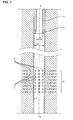
- Figure 1 shows a portion of an oil borehole well lined with casing C and having a cylindrical wall of vertical axis X-X'.
- a segment Z of the casing presents perforations p that are producing water and that it is desired to plug by patching.
- Reference EC designates completion equipment held in place by an annular centering member A and of inside diameter d that is considerably smaller than the diameter D 0 of the casing.
- the diameter d is about 100 mm, while the diameter D 0 is about 155 mm.
- Figure 8 shows the same portion of the well after a patch 4 has been put into place in the portion Z so as to make this zone leakproof, isolating the perforations p from the inside of the well by interposing a cylindrical metal wall 40.
- the inside diameter D of said wall is important for the inside diameter D of said wall to be greater than or equal to d so as to allow access to the bottom portion of the well after treatment by tools that have been able to pass through the completion of diameter d .
- the invention makes it easy to do so.
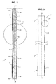
- the apparatus of the invention shown in Figures 2 to 6 comprises a tubular tool 1 essentially constituted by a cylindrical mandrel 2 of axis X-X', e.g. made of steel, and surrounded by a pair of inflatable packers 3 that are likewise cylindrical, each having its wall in the form of a diaphragm of flexible and elastic material that can withstand pressure and corrosion, e.g. of rubber or of elastomer.
- the two packers 3 are carried by the mandrel 2 coaxially with the mandrel and situated a certain distance apart in the axial direction.
- each packer is secured hermetically at its ends to endpieces 30, 30' , one of which is movable axially so as to accommodate the reduction in the length of the packer associated with its radial expansion, and conversely the increase in its length on deflation.
- the mandrel At its free bottom end, the mandrel carries a cap 62 forming an abutment for the bottom endpiece 30'.
- a ring to secured to the mandrel forms an abutment for the top endpiece 30'.
- the mandrel presents a longitudinal channel 6 for connection to a source of liquid under high pressure and that opens out through a radial orifice or a plurality of radial orifices 60 into the inside of each packer 3.
- the mandrel 2 presents another longitudinal channel 7 for connection to a source of liquid under high pressure.
- the channel 7 opens to the outside in the central zone of the mandrel 2 via a radial orifice or a plurality of radial orifices 70.
- the channels 7 open to the outside of the mandrel 2 via radial orifices 70 between the two inflatable packers 3.
- the tool with its inflatable packers 3 has the same structure as a double inflatable packer device of the kind commonly used in the oil industry.
- the patch 4 that is to be used for patching purposes comprises a cylindrical tube made of metal, preferably steel, and of relatively fine wall thickness.
- Its length corresponds substantially to the length of the tool, and its inside diameter is greater than that of the tool 1 and of its packers 3.
- the tool 1 can thus be engaged axially inside the tubular patch 4, as represented by arrow Q in Figure 6 .
- each packer 3 is in register with one of the two end portions 5 of the patch 4.
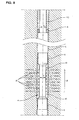
- the portions 5 are mechanically reinforced so that their resistance to deformation in radial expansion is considerably greater than that of the central portion 40 of the patch. More precisely, and as can be seen in particular in Figure 5 , the wall of the patch in this zone, referenced 41, is surrounded by a cylindrical metal ring 51, thereby increasing the total thickness of the wall.
- the ring 51 is provided on its outside with a sealing coating 52.
- the coating is an annular layer of flexible and elastic material (e.g. elastomer or rubbers, that is advantageously crenellated, so as to have circumferential grooves between solid portions in relief, so that each of these portions can deform appropriately when the portion 5 is expanded radially and pressed with force against the casing.
- flexible and elastic material e.g. elastomer or rubbers, that is advantageously crenellated, so as to have circumferential grooves between solid portions in relief, so that each of these portions can deform appropriately when the portion 5 is expanded radially and pressed with force against the casing.
- the coating layer could be replaced by a series of adjacent O-rings received in grooves formed in the periphery of the ring 51.
- material for making the coating or the O-rings it is advantageous to use a material that is suitable for swelling on coming into contact with a liquid, in particular the liquid that is present in the well (water, mud, or oil, in particular), so as to further improve sealing.
- the packers 3 are inflated a little by delivering fluid under moderate pressure thereto via the channel 6 and the orifices 61, the pressure being sufficient to hold the tool 1 by friction against the patch 4.
- the assembly is suspended from mounting and guide members, e.g. hollow rods of known type of the kind used for putting into place and removing conventional packers.
- the supply of the liquid under pressure takes place via the insides of the suspension rods.
- the outside diameter of the assembly made up of the tool and the packer is selected to be smaller than the inside diameter d of the completion equipment EC, so that it can travel axially therealong.
- Its length is selected to be a little longer than the length of the zone 8 that is to be treated; it is a few meters long, for example.
- Figure 7 shows the assembly being lowered (arrow F) through the completion equipment EC towards the perforated zone Z that is to be patched.
- a high pressure liquid LHP is then fed into each of the inflatable packers 3 via the channel 6 (arrow I) and the orifices 6 (arrows i ).
- the value of this pressure is selected to be sufficient to cause the packers to expand radially together with the end portions of the patch, against which the packers bear.
- the pressure of the second fluid lhp is significantly lower than that of the first fluid LHP, while nevertheless being sufficient to cause the central portion 40 of the patch to expand radially, its wall not being reinforced.
- the pressure difference e.g. about 5 megapascals (MPa), or 50 bars, is selected to be sufficient to prevent the fluid lhp escaping in unwanted manner to the outside of the patch between the outside walls of the packers and the inside wall of the patch.
- the central portion 40 of the patch is thus expanded radially by hydroforming.
- the pressure of each liquid can be controlled so as to obtain the desired deformations of the end portions 5 and of the central portion 40.
- each portion of the patch leads automatically to a reduction in the wall thickness of said portion.
- Figure 7C shows an intermediate stage corresponding to the portions 5 coming into contact with the inside wall of the casing C.
- the end portions 5 end up taking on a "tulip" shape with a cylindrical portion pressing intimately and firmly in leaktight manner against the inside wall of the casing 3.
- the packers 3 are deflated so that they return to the initial cylindrical shape due to the reduction in pressure, thus allowing liquid to escape via the orifices 60 (arrows i') and the channel 6 (arrow I'), as shown in Figure 7E .
- the liquid lhp that was trapped between the inflated packers 3 inside the patch can then escape freely into the well.
- the tool can then be withdrawn from the well (arrow F') by being passed back through the completion equipment EC, as shown in Figure 7'E .
- the minimum diameter D of the patch 4 is greater than the diameters of the completion equipment EC, so that it too does not impede operation of the well. It can be advantageous to limit the expansion of the central portion 40 so that a relatively large angular space exists around its periphery, which space can be used, for example, to receive certain pieces of equipment such as sensors, and as explained below.
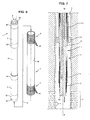
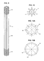
- the patch 8 shown in Figures 9 and 10 possesses a wall that is generally cylindrical, but the wall is folded in the longitudinal direction.
- This folding is performed over the entire length of the patch.
- the end portions 81 are reinforced relative to the central portion 80, and the end portions 81 are lined with a sealing coating.
- the wall of the patch presents corrugations 9 giving it a somewhat "daisy" shape.
- This folded shape enables the central portion 8 to be expanded to a relatively large extent.
- the central portion 80 of the patch is strictly cylindrical, being of constant diameter along its entire length.
- a given tool can be used several times over for putting a plurality of patches into place in a single well or in different wells.
- the patch can be put into place by passing through a patch that has already been put into place.
- Length of the central portion 40 lying in the range 2 m to 12 m; e.g. 10 m.
- Length of the end portions 5 lying in the range 0.3 m to 1 m; e.g. 0.5 m.
- Diameter before expansion lying in the range 80 mm to 120 mm (e.g. 100 mm).
- Diameter after expansion is complete lying in the range 100 mm to 150 mm (e.g. 130 mm) for the central portion 40, and lying in the range 120 mm to 180 mm (e.g. 155 mm) in the end portions 5.
- sensors e.g. temperature sensors, pressure sensors, sensors for sensing the pressure of a gas or of some other given substance, etc.
- sensors e.g. temperature sensors, pressure sensors, sensors for sensing the pressure of a gas or of some other given substance, etc.
- the invention provides a convenient and reliable way of putting such sensors into place, and enables them to be thoroughly isolated inside the well once they have been put into place.
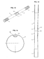
- Figure 11 shows a patch 4 whose cylindrical portion 40 carries a sensor 100; it may be cylindrical in shape, and of diameter that is considerably smaller than that of the patch. It is positioned longitudinally, along a generator line of the patch, and is adjacent to its central portion 40.
- Appropriate fastener means such as a pair of resilient annular straps L1 and L2 serve to hold it in place.
- the patch 4 is put into place as described above.
- the sensor 100 is thoroughly isolated inside the casing C in the peripheral space that surrounds the central portion 40, which space is hermetically sealed at both ends by the expanded portions 5.
- the central portion presents a small longitudinal depression 400 made by stamping and serving initially to house the sensor.
- the sensor does not project outside the cylindrical envelope of the patch, thus avoiding any risk of the sensor catching and possibly being damaged while the tool and patch assembly is being lowered down the well, in particular through its completion equipment.
- the setback in the wall 400 deploys like the corrugations in the folded patch shown in Figures 9 and 10 , so the central portion 40 takes on a cylindrical shape.
Landscapes
- Geology (AREA)
- Life Sciences & Earth Sciences (AREA)
- Engineering & Computer Science (AREA)
- Mining & Mineral Resources (AREA)
- Physics & Mathematics (AREA)
- Geochemistry & Mineralogy (AREA)
- Fluid Mechanics (AREA)
- General Life Sciences & Earth Sciences (AREA)
- Environmental & Geological Engineering (AREA)
- Geophysics (AREA)
- Pipe Accessories (AREA)
- Shaping Metal By Deep-Drawing, Or The Like (AREA)
- Measuring Fluid Pressure (AREA)
- Consolidation Of Soil By Introduction Of Solidifying Substances Into Soil (AREA)
- Tubes (AREA)
- Sampling And Sample Adjustment (AREA)
- Dowels (AREA)
Claims (11)
- Procédé de chemisage d'un puits ou d'une canalisation, par exemple d'un cuvelage (C), présentant une portion à traiter, notamment à réparer et/ou à boucher, par hydroformage d'une chemise tubulaire métallique dont le diamètre initial est sensiblement inférieur à celui du puits ou de la canalisation, selon lequel :- on introduit axialement à l'intérieur de cette chemise (4) un outil (1) comprenant un mandrin (2) sur lequel sont montés deux obturateurs gonflables (3), radialement expansibles sous l'action d'une pression hydraulique interne, ces deux obturateurs (3) étant axialement écartés l'un de l'autre, d'une distance sensiblement égale, ou légèrement inférieure, à la longueur de la chemise ;- on positionne ledit outil (1) à l'intérieur de la chemise de telle sorte que les obturateurs (3) se trouvent en regard de ses portions d'extrémité (5) ;- on introduit axialement dans le puits ou la canalisation l'ensemble constitué par l'outil (1) et la chemise (4), et on le positionne en regard de la zone (Z) à chemiser ;- on gonfle lesdits obturateurs (3) avec une pression élevée, suffisante pour qu'ils provoquent l'expansion radiale des deux portions d'extrémité (5) de la chemise en les appliquant de manière étanche contre la paroi interne du puits ou de la canalisation ;- on dégonfle lesdits obturateurs (3), et on retire l'outil (1) du puits ou de la canalisation ;
caractérisé par le fait que l'on fait usage d'une chemise (4) dont lesdites portions d'extrémité (5) sont renforcées mécaniquement, leur épaisseur étant supérieure à l'épaisseur de la partie centrale (40) de la chemise. - Procédé selon la revendication 1, caractérisé par le fait que, après que lesdits obturateurs (3) aient été gonflés, au moins partiellement, de manière à appliquer les deux portions d'extrémité (5) de la chemise (4) de manière étanche contre la paroi interne du puits ou de la canalisation, on introduit un second fluide sous pression à l'intérieur de la chemise (4), entre les deux obturateurs (3), de manière à provoquer également une expansion radiale, par hydroformage, de la partie centrale (40) de la chemise, située entre ses deux portions d'extrémité (5), la pression de gonflage des obturateurs (3) étant sensiblement supérieure à celle de ce second fluide.
- Procédé selon la revendication 2, caractérisé par le fait qu'on le met en oeuvre en plusieurs étapes, chaque étape comprenant deux phases successives, selon lesquelles :a) dans une première phase, on provoque une expansion radiale partielle des portions d'extrémité (5) afin d'obtenir une augmentation déterminée du diamètre de ces portions, ceci on gonflant les obturateurs (3) à une pression donnée, directement fonction de l'augmentation de diamètre souhaitée ;b) dans une seconde phase, on provoque l'expansion radiale partielle du reste de la chemise, c'est-à-dire de sa partie centrale (40), par hydroformage sous l'action d'une pression de moindre valeur, choisie pour obtenir une augmentation de son diamètre jusqu'à une valeur désirée ;
on réitère l'opération une ou plusieurs fois, jusqu'à obtenir le diamètre d'expansion désiré pour la partie centrale de la chemise et, enfin, on provoque l'expansion finale des portions d'extrémité (5) afin que celles-ci viennent s'appliquer intimement, de manière étanche, contre la paroi interne du puits ou de la canalisation. - Procédé selon l'une des revendications 1 à 3, caractérisé par le fait que lorsqu'on a positionné ledit outil (1) à l'intérieur de la chemise (4), on gonfle légèrement les obturateurs (3) de manière à rendre l'outil solidaire, par friction, de la chemise (4).
- Procédé selon l'une des revendications 1 à 4, caractérisé par le fait qu'on met en place au moins un capteur (100) entre la partie centrale (40) de la chemise et la paroi interne du puits ou de la canalisation, ledit capteur (100) étant fixé à l'extérieur de la partie centrale (40) de la chemise avant l'opération.
- Chemise tubulaire à portions d'extrémité renforcées mécaniquement, destinée à la mise en oeuvre d'un procédé de chemisage selon l'une quelconque des revendications 1 à 5, caractérisée par le fait que l'épaisseur desdites portions d'extrémité (5) est supérieure à celle de la partie centrale (40) de la chemise, et que ses portions d'extrémité (5) sont munies d'une garniture externe (52), par exemple en caoutchouc, naturel ou synthétique, apte à améliorer l'étanchéité de leur liaison contre la paroi interne du puits ou de la canalisation.
- Chemise selon la revendication 6, caractérisée par le fait qu'elle est renforcée dans ses portions d'extrémité (5) au moyen d'une bague extérieure (51) faisant office de frette, emmanchée sur sa paroi (41).
- Chemise selon la revendication 6 ou 7, caractérisé par le fait que ladite garniture externe (52) est en matériau auto-gonflant, apte à se dilater lorsqu'il est en contact avec un liquide, notamment avec de l'eau ou avec du pétrole.
- Chemise selon l'une des revendications 6 à 8, caractérisée par le fait que sa partie centrale (80), située entre ses portions d'extrémité (81), possède une paroi plissée longitudinalement, ce qui favorise son expansion radiale par déploiement de ses ondulations (9), sous l'effet d'une pression interne.
- Chemise selon l'une des revendications 6 à 9, caractérisée par le fait qu'elle est munie d'au moins un capteur (100) fixé à sa partie centrale (40), à l'extérieur de sa paroi.
- Chemise selon la revendication 10, caractérisée par le fait que le capteur (100) est logé dans un renfoncement de paroi (400) de ladite partie centrale (40).
Applications Claiming Priority (2)
| Application Number | Priority Date | Filing Date | Title |
|---|---|---|---|
| FR0604987A FR2901837B1 (fr) | 2006-06-06 | 2006-06-06 | Procede et dispositif de chemisage d'un puits par hydroformage d'une chemise tubulaire metallique, et chemise destinee a cet usage |
| PCT/EP2006/068361 WO2007140820A1 (fr) | 2006-06-06 | 2006-11-10 | Procédé et appareil permettant le rapiéçage d'un puits par hydroformage d'une pièce de rapiéçage métallique tubulaire, et pièce de rapiéçage à cette fin |
Publications (2)
| Publication Number | Publication Date |
|---|---|
| EP2024601A1 EP2024601A1 (fr) | 2009-02-18 |
| EP2024601B1 true EP2024601B1 (fr) | 2010-09-29 |
Family
ID=37758867
Family Applications (1)
| Application Number | Title | Priority Date | Filing Date |
|---|---|---|---|
| EP06819405A Not-in-force EP2024601B1 (fr) | 2006-06-06 | 2006-11-10 | Procédé et appareil permettant le rapiéçage d'un puits par hydroformage d'une pièce de rapiéçage métallique tubulaire, et pièce de rapiéçage à cette fin |
Country Status (10)
| Country | Link |
|---|---|
| US (1) | US8235075B2 (fr) |
| EP (1) | EP2024601B1 (fr) |
| JP (1) | JP4808807B2 (fr) |
| CN (1) | CN101460699B (fr) |
| AT (1) | ATE483093T1 (fr) |
| DE (1) | DE602006017271D1 (fr) |
| FR (1) | FR2901837B1 (fr) |
| NO (1) | NO20090087L (fr) |
| RU (1) | RU2008147129A (fr) |
| WO (1) | WO2007140820A1 (fr) |
Families Citing this family (69)
| Publication number | Priority date | Publication date | Assignee | Title |
|---|---|---|---|---|
| GB2464233B (en) * | 2007-08-03 | 2012-06-27 | Shell Int Research | Method for altering the stress state of a formation and/or a tubular |
| RU2378489C1 (ru) * | 2008-09-05 | 2010-01-10 | Открытое акционерное общество "Татнефть" им. В.Д. Шашина | Устройство для перекрытия зоны осложнения при бурении скважины |
| RU2386782C1 (ru) * | 2009-02-27 | 2010-04-20 | Открытое акционерное общество "Татнефть" им. В.Д. Шашина | Устройство для поинтервального перекрытия зоны осложнения при бурении скважины |
| NO330232B1 (no) * | 2009-06-10 | 2011-03-07 | Bronnteknologiutvikling As | Tetningsanordning for ror |
| CN101705808B (zh) | 2009-12-11 | 2012-05-30 | 安东石油技术(集团)有限公司 | 套管外存在窜槽的油气井的控流过滤器管柱分段控流方法 |
| CN101705809B (zh) * | 2009-12-11 | 2012-12-26 | 安东石油技术(集团)有限公司 | 一种存在防砂管油气井的控流过滤器管柱分段控流方法 |
| FR2958966B1 (fr) * | 2010-04-20 | 2016-02-12 | Saltel Ind | Procede et dispositif d'obturation d'un puits au moyen d'un bouchon expansible, bouchon pour la mise en oeuvre du procede, et outil extracteur adapte pour le retirer |
| RU2439283C1 (ru) * | 2010-07-02 | 2012-01-10 | Открытое акционерное общество "Татнефть" имени В.Д. Шашина | Устройство для поинтервального перекрытия зон осложнений при бурении скважин |
| RU2438000C1 (ru) * | 2010-07-02 | 2011-12-27 | Открытое акционерное общество "Татнефть" имени В.Д. Шашина | Способ установки пластыря в обсадной колонне труб |
| RU2425953C1 (ru) * | 2010-08-27 | 2011-08-10 | Открытое акционерное общество "Татнефть" имени В.Д. Шашина | Устройство для перекрытия зоны осложнения при бурении скважины |
| US20120097391A1 (en) | 2010-10-22 | 2012-04-26 | Enventure Global Technology, L.L.C. | Expandable casing patch |
| CN101979785A (zh) * | 2010-11-01 | 2011-02-23 | 王清电 | 水井修复机 |
| WO2013043489A2 (fr) | 2011-09-20 | 2013-03-28 | Saudi Arabian Oil Company | Colonne de forage perméable à perte de circulation |
| US9470059B2 (en) | 2011-09-20 | 2016-10-18 | Saudi Arabian Oil Company | Bottom hole assembly for deploying an expandable liner in a wellbore |
| CN103061700B (zh) * | 2011-10-21 | 2016-12-07 | 中国石油化工股份有限公司 | 套管错断水平井拨正修复方法及其专用一体化工具 |
| FR2996247B1 (fr) * | 2012-10-03 | 2015-03-13 | Saltel Ind | Procede de fracturation hydraulique et materiel correspondant |
| US20140109981A1 (en) * | 2012-10-18 | 2014-04-24 | Schlumberger Technology Corporation | Management technique for hydraulic line leaks |
| FR2997440B1 (fr) * | 2012-10-26 | 2014-11-28 | Saltel Ind | Procede et dispositif de chemisage d'un puits par hydroformage |
| US9605519B2 (en) | 2013-07-24 | 2017-03-28 | Baker Hughes Incorporated | Non-ballistic tubular perforating system and method |
| US9441455B2 (en) * | 2013-09-27 | 2016-09-13 | Baker Hughes Incorporated | Cement masking system and method thereof |
| US9410398B2 (en) | 2013-09-27 | 2016-08-09 | Baker Hughes Incorporated | Downhole system having compressable and expandable member to cover port and method of displacing cement using member |
| US9541230B2 (en) * | 2014-08-15 | 2017-01-10 | Jeffrey M. Tanner | Pipe tool positioning system |
| CN106368638B (zh) * | 2015-07-23 | 2019-04-09 | 中国石油天然气股份有限公司 | 套管破损封堵工具及封堵方法 |
| CN105064942B (zh) * | 2015-08-25 | 2018-02-23 | 元玉石 | 一种气囊补井工具 |
| JP2017115910A (ja) * | 2015-12-21 | 2017-06-29 | 鹿島建設株式会社 | 配管の閉塞方法、及び、配管の撤去方法 |
| US10418874B2 (en) * | 2016-07-14 | 2019-09-17 | Siemens Industry, Inc. | Methods and system for creating spacing between insulated coils of electrodynamic machines |
| CN106326667B (zh) * | 2016-08-31 | 2019-02-19 | 中国石油集团川庆钻探工程有限公司长庆井下技术作业公司 | 一种完井封隔器卡瓦段套管极限承载能力计算模型与方法 |
| CN108086936A (zh) * | 2016-11-22 | 2018-05-29 | 中国石油化工股份有限公司 | 一种异形截面套管补贴工具 |
| CN106678491B (zh) * | 2016-12-01 | 2018-11-16 | 重庆友擘机械制造有限公司 | 气密性检测封堵装置 |
| CN106869846B (zh) * | 2017-02-24 | 2023-01-03 | 中国石油化工股份有限公司 | 一种井下套管贴补方法 |
| CN106996901A (zh) * | 2017-03-23 | 2017-08-01 | 中国海洋石油总公司 | 管内环焊缝试压工具及试压方法 |
| CN106931272B (zh) * | 2017-05-03 | 2019-07-09 | 成都鼎胜科技有限公司 | 高压地下储气井井下泄漏修补装置 |
| EP3415711A1 (fr) * | 2017-06-13 | 2018-12-19 | Welltec A/S | Outil de pose de pièce rapportée de fond de trou |
| CN107271262A (zh) * | 2017-07-18 | 2017-10-20 | 中国海洋石油总公司 | 一种管内单焊缝试压装置 |
| GB2578535B (en) * | 2017-08-02 | 2022-08-31 | Halliburton Energy Services Inc | Wear sleeve |
| CN109538194B (zh) * | 2017-09-18 | 2023-04-18 | 中国石油化工股份有限公司 | 一种连续油管井下快速找漏工艺管柱及使用方法 |
| AU2017439376B2 (en) | 2017-11-13 | 2023-06-01 | Halliburton Energy Services, Inc. | Swellable metal for non-elastomeric O-rings, seal stacks, and gaskets |
| EP3495602A1 (fr) * | 2017-12-07 | 2019-06-12 | Welltec Oilfield Solutions AG | Système de réparation de fond de trou |
| MX2020007696A (es) | 2018-02-23 | 2020-11-12 | Halliburton Energy Services Inc | Metal hinchable para empacador hinchable. |
| US11519261B2 (en) * | 2018-04-10 | 2022-12-06 | Halliburton Energy Services, Inc. | Deployment of downhole sensors |
| CN108533208B (zh) * | 2018-06-05 | 2024-05-14 | 南通中杰石油科研仪器有限公司 | 普通丝扣油管气密封用的弹性气体密封垫及密封方法 |
| US10767452B2 (en) * | 2018-06-06 | 2020-09-08 | Saudi Arabian Oil Company | Liner installation with inflatable packer |
| US11814920B2 (en) * | 2019-01-21 | 2023-11-14 | Schlumberger Technology Corporation | System and methodology for through tubing patching |
| NO20210729A1 (en) | 2019-02-22 | 2021-06-04 | Halliburton Energy Services Inc | An Expanding Metal Sealant For Use With Multilateral Completion Systems |
| CA3138868C (fr) | 2019-07-16 | 2024-03-19 | Halliburton Energy Services, Inc. | Elements metalliques expansibles composites presentant un renforcement |
| CN110242238A (zh) * | 2019-07-24 | 2019-09-17 | 屈波 | 用于管道的内衬复合装置 |
| GB2599552B (en) | 2019-07-31 | 2023-04-26 | Halliburton Energy Services Inc | Methods to monitor a metallic sealant deployed in a wellbore, methods to monitor fluid displacement, and downhole metallic sealant measurement systems |
| CN110485960A (zh) * | 2019-08-12 | 2019-11-22 | 屈波 | 管道复合内衬装置 |
| AU2019462937B2 (en) * | 2019-08-21 | 2025-07-31 | Halliburton Energy Services, Inc. | An expandable metal sealant wellbore casing patch |
| US11254045B2 (en) | 2019-08-26 | 2022-02-22 | Jeffrey M. Tanner | Method and system for lining pipes |
| CN112696164A (zh) * | 2019-10-22 | 2021-04-23 | 中国石油化工股份有限公司 | 一种液压套管补贴管柱及方法 |
| US11519239B2 (en) | 2019-10-29 | 2022-12-06 | Halliburton Energy Services, Inc. | Running lines through expandable metal sealing elements |
| US12480373B2 (en) | 2019-11-13 | 2025-11-25 | Halliburton Energy Services, Inc. | Actuating a downhole device with a reactive metal |
| US11761290B2 (en) | 2019-12-18 | 2023-09-19 | Halliburton Energy Services, Inc. | Reactive metal sealing elements for a liner hanger |
| US11098835B2 (en) | 2020-01-24 | 2021-08-24 | Trinity Bay Equipment Holdings, LLC | Seal system and method |
| CN114486550A (zh) * | 2020-10-27 | 2022-05-13 | 中国石油化工股份有限公司 | 一种井下变温补贴管自由胀形试验方法以及试验系统 |
| CN114482894B (zh) * | 2020-10-27 | 2024-03-01 | 中国石油化工股份有限公司 | 一种井下筛管液压成形补贴系统及其施工方法 |
| US11761293B2 (en) | 2020-12-14 | 2023-09-19 | Halliburton Energy Services, Inc. | Swellable packer assemblies, downhole packer systems, and methods to seal a wellbore |
| US11572749B2 (en) | 2020-12-16 | 2023-02-07 | Halliburton Energy Services, Inc. | Non-expanding liner hanger |
| CN112709871B (zh) * | 2020-12-31 | 2022-10-14 | 太原三凌通风设备有限公司 | 一种防泄漏的化工管道系统 |
| US11578498B2 (en) | 2021-04-12 | 2023-02-14 | Halliburton Energy Services, Inc. | Expandable metal for anchoring posts |
| US11879304B2 (en) | 2021-05-17 | 2024-01-23 | Halliburton Energy Services, Inc. | Reactive metal for cement assurance |
| CN113846984B (zh) * | 2021-09-23 | 2024-06-28 | 瑞诺思新能源科技(北京)有限公司 | 电能驱动的膨胀工具总成及其实现膨胀管补贴的方法 |
| CN114135244B (zh) * | 2021-11-30 | 2023-05-26 | 西南石油大学 | 一种用于随钻封堵的水力可变级膨胀工具 |
| CN116263074B (zh) * | 2021-12-13 | 2025-07-25 | 中国石油天然气股份有限公司 | 一种油井套管再造装置及再造方法 |
| CN116044390B (zh) * | 2023-02-20 | 2025-09-16 | 煤炭科学技术研究院有限公司 | 地应力测试装置 |
| US12060963B1 (en) * | 2023-04-19 | 2024-08-13 | Danny Warren Consulting, LLC. | Method and system for encapsulating in-ground asbestos concrete pipe |
| CN117189029A (zh) * | 2023-09-26 | 2023-12-08 | 国家能源集团宁夏煤业有限责任公司 | 注浆设备和套管跑落处理方法 |
| US12612843B2 (en) | 2023-12-26 | 2026-04-28 | Halliburton Energy Services, Inc. | Mechanical support for expandable liner hanger |
Citations (3)
| Publication number | Priority date | Publication date | Assignee | Title |
|---|---|---|---|---|
| US6530574B1 (en) * | 2000-10-06 | 2003-03-11 | Gary L. Bailey | Method and apparatus for expansion sealing concentric tubular structures |
| EP1428974A2 (fr) * | 1998-05-28 | 2004-06-16 | Halliburton Energy Services, Inc. | Jonction expansible de puits de forage |
| WO2005086041A1 (fr) * | 2004-03-02 | 2005-09-15 | Mena Pineiro Francisco Javier | Procede de personnalisation de pieces utilise dans la production en serie |
Family Cites Families (22)
| Publication number | Priority date | Publication date | Assignee | Title |
|---|---|---|---|---|
| US2812025A (en) * | 1955-01-24 | 1957-11-05 | James U Teague | Expansible liner |
| US3618639A (en) * | 1969-11-24 | 1971-11-09 | Cues Inc | Packer for sealing pipe leaks |
| GB1340068A (en) * | 1970-09-22 | 1973-12-05 | Insituform Pipes & Structures | Lining of surfaces defining passageways |
| USRE30802E (en) * | 1976-03-26 | 1981-11-24 | Combustion Engineering, Inc. | Method of securing a sleeve within a tube |
| JPS58207480A (ja) * | 1982-05-27 | 1983-12-02 | 東邦天然ガス株式会社 | 井戸の破孔修理方法並びに井戸の破孔修理具 |
| DE3637946A1 (de) * | 1986-11-07 | 1988-05-19 | Klaus Zawisla Gmbh & Co Kg | Verfahren zum sanieren eines brunnens |
| US4830109A (en) * | 1987-10-28 | 1989-05-16 | Cameron Iron Works Usa, Inc. | Casing patch method and apparatus |
| US5027895A (en) * | 1989-10-16 | 1991-07-02 | Barton Kenneth S | Expandable packer apparatus |
| MY108743A (en) * | 1992-06-09 | 1996-11-30 | Shell Int Research | Method of greating a wellbore in an underground formation |
| DE4406167C2 (de) * | 1994-02-25 | 1997-04-24 | Bbc Reaktor Gmbh | Verfahren zum Erzielen einer dichten Verbindung zwischen einem Rohr und einer Hülse |
| US5794663A (en) * | 1994-08-19 | 1998-08-18 | Lmk Enterprises | Apparatus for repairing a pipeline and method for using same |
| CA2356194C (fr) * | 1998-12-22 | 2007-02-27 | Weatherford/Lamb, Inc. | Procedes et materiel de faconnage et d'assemblage de tuyaux |
| US6478091B1 (en) * | 2000-05-04 | 2002-11-12 | Halliburton Energy Services, Inc. | Expandable liner and associated methods of regulating fluid flow in a well |
| GB2389606B (en) * | 2000-12-22 | 2005-06-29 | E2Tech Ltd | Method and apparatus for downhole remedial or repair operations |
| US6799632B2 (en) * | 2002-08-05 | 2004-10-05 | Intelliserv, Inc. | Expandable metal liner for downhole components |
| US7828068B2 (en) * | 2002-09-23 | 2010-11-09 | Halliburton Energy Services, Inc. | System and method for thermal change compensation in an annular isolator |
| US7090006B2 (en) * | 2002-11-05 | 2006-08-15 | Conocophillips Company | Replaceable liner for metal lined composite risers in offshore applications |
| GB0303422D0 (en) * | 2003-02-13 | 2003-03-19 | Read Well Services Ltd | Apparatus and method |
| US6994118B2 (en) * | 2003-12-04 | 2006-02-07 | Blue Sky Forever, Inc. | Device and method for repairing pipe using hydrophilic seals |
| US20060042801A1 (en) * | 2004-08-24 | 2006-03-02 | Hackworth Matthew R | Isolation device and method |
| US7240697B2 (en) * | 2004-10-21 | 2007-07-10 | Mechanical Research & Design, Inc. | Apparatus and method for isolating and testing a segment of pipelines |
| US7401647B2 (en) * | 2005-11-14 | 2008-07-22 | Baker Hughes Incorporated | Flush mounted tubular patch |
-
2006
- 2006-06-06 FR FR0604987A patent/FR2901837B1/fr not_active Expired - Fee Related
- 2006-11-10 DE DE200660017271 patent/DE602006017271D1/de active Active
- 2006-11-10 CN CN2006800548607A patent/CN101460699B/zh not_active Expired - Fee Related
- 2006-11-10 WO PCT/EP2006/068361 patent/WO2007140820A1/fr not_active Ceased
- 2006-11-10 US US12/303,474 patent/US8235075B2/en not_active Expired - Fee Related
- 2006-11-10 EP EP06819405A patent/EP2024601B1/fr not_active Not-in-force
- 2006-11-10 JP JP2009513551A patent/JP4808807B2/ja not_active Expired - Fee Related
- 2006-11-10 RU RU2008147129/03A patent/RU2008147129A/ru not_active Application Discontinuation
- 2006-11-10 AT AT06819405T patent/ATE483093T1/de not_active IP Right Cessation
-
2009
- 2009-01-06 NO NO20090087A patent/NO20090087L/no not_active Application Discontinuation
Patent Citations (3)
| Publication number | Priority date | Publication date | Assignee | Title |
|---|---|---|---|---|
| EP1428974A2 (fr) * | 1998-05-28 | 2004-06-16 | Halliburton Energy Services, Inc. | Jonction expansible de puits de forage |
| US6530574B1 (en) * | 2000-10-06 | 2003-03-11 | Gary L. Bailey | Method and apparatus for expansion sealing concentric tubular structures |
| WO2005086041A1 (fr) * | 2004-03-02 | 2005-09-15 | Mena Pineiro Francisco Javier | Procede de personnalisation de pieces utilise dans la production en serie |
Also Published As
| Publication number | Publication date |
|---|---|
| CN101460699B (zh) | 2013-07-17 |
| US20090188569A1 (en) | 2009-07-30 |
| CN101460699A (zh) | 2009-06-17 |
| DE602006017271D1 (de) | 2010-11-11 |
| NO20090087L (no) | 2009-01-06 |
| ATE483093T1 (de) | 2010-10-15 |
| FR2901837A1 (fr) | 2007-12-07 |
| JP2009540148A (ja) | 2009-11-19 |
| FR2901837B1 (fr) | 2015-05-15 |
| WO2007140820A1 (fr) | 2007-12-13 |
| US8235075B2 (en) | 2012-08-07 |
| EP2024601A1 (fr) | 2009-02-18 |
| JP4808807B2 (ja) | 2011-11-02 |
| RU2008147129A (ru) | 2010-07-20 |
Similar Documents
| Publication | Publication Date | Title |
|---|---|---|
| US8235075B2 (en) | Method and apparatus for patching a well by hydroforming a tubular metal patch, and a patch for this purpose | |
| CN101778994B (zh) | 利用可膨胀囊状物来给井或者管道加衬套的方法 | |
| US4424861A (en) | Inflatable anchor element and packer employing same | |
| US4413653A (en) | Inflation anchor | |
| US8157007B2 (en) | Method for casing using multiple expanded areas and using at least one inflatable bladder | |
| US8091640B2 (en) | Method and device for cementing a well or a pipe | |
| US5964288A (en) | Device and process for the lining of a pipe branch, particuarly in an oil well | |
| US6695067B2 (en) | Wellbore isolation technique | |
| AU2019303954B2 (en) | Method of remediating leaks in a cement sheath surrounding a wellbore tubular | |
| JPH05507331A (ja) | 円筒体のケーシング処理及び/又は裏張りを行なうための予備成形体、装置、及び方法 | |
| US20150218917A1 (en) | Method for repairing a liner hanger, device and blank for implementation thereof | |
| EP0357711A1 (fr) | Procede et dispositif permettant de reparer des enveloppes et analogues | |
| GB2368082A (en) | Expandable bistable tubing | |
| US20120273199A1 (en) | Nitinol Through Tubing Bridge Plug | |
| EP2697551B1 (fr) | Procédé et appareil de reprofilage de colonne | |
| EP3665363A1 (fr) | Système de pièce rapportée pour tubage | |
| US20020083990A1 (en) | Method and apparatus for repairing a pipeline | |
| US20150275631A1 (en) | Method and device for lining a well using hydroforming | |
| US7828054B2 (en) | Packer cable sealing system | |
| US5236201A (en) | Reinforcement structure for inflatable downhole packers | |
| NO322455B1 (no) | Oppblasbar pakningsinnretning som omfatter en elastomerisk kappe | |
| NO322917B1 (no) | Anordning ved blaere for en oppblasbar pakningsinnretning | |
| US6458233B2 (en) | Method for manufacturing a wall thickness program into an elastomeric tubular component for incorporation into a packing device for use in a subterranean well | |
| EP0632874A1 (fr) | Dispositif destine a la reparation des oleoducs et comportant des elements gonflables | |
| AU656235B2 (en) | Improved reinforcement structure for inflatable downhole packers |
Legal Events
| Date | Code | Title | Description |
|---|---|---|---|
| PUAI | Public reference made under article 153(3) epc to a published international application that has entered the european phase |
Free format text: ORIGINAL CODE: 0009012 |
|
| 17P | Request for examination filed |
Effective date: 20081202 |
|
| AK | Designated contracting states |
Kind code of ref document: A1 Designated state(s): AT BE BG CH CY CZ DE DK EE ES FI FR GB GR HU IE IS IT LI LT LU LV MC NL PL PT RO SE SI SK TR |
|
| AX | Request for extension of the european patent |
Extension state: AL BA HR MK RS |
|
| 17Q | First examination report despatched |
Effective date: 20090716 |
|
| GRAP | Despatch of communication of intention to grant a patent |
Free format text: ORIGINAL CODE: EPIDOSNIGR1 |
|
| RAP1 | Party data changed (applicant data changed or rights of an application transferred) |
Owner name: SALTEL INDUSTRIES |
|
| GRAS | Grant fee paid |
Free format text: ORIGINAL CODE: EPIDOSNIGR3 |
|
| GRAA | (expected) grant |
Free format text: ORIGINAL CODE: 0009210 |
|
| AK | Designated contracting states |
Kind code of ref document: B1 Designated state(s): AT BE BG CH CY CZ DE DK EE ES FI FR GB GR HU IE IS IT LI LT LU LV MC NL PL PT RO SE SI SK TR |
|
| REG | Reference to a national code |
Ref country code: GB Ref legal event code: FG4D |
|
| REG | Reference to a national code |
Ref country code: CH Ref legal event code: EP |
|
| REG | Reference to a national code |
Ref country code: IE Ref legal event code: FG4D |
|
| REF | Corresponds to: |
Ref document number: 602006017271 Country of ref document: DE Date of ref document: 20101111 Kind code of ref document: P |
|
| PG25 | Lapsed in a contracting state [announced via postgrant information from national office to epo] |
Ref country code: FI Free format text: LAPSE BECAUSE OF FAILURE TO SUBMIT A TRANSLATION OF THE DESCRIPTION OR TO PAY THE FEE WITHIN THE PRESCRIBED TIME-LIMIT Effective date: 20100929 Ref country code: LT Free format text: LAPSE BECAUSE OF FAILURE TO SUBMIT A TRANSLATION OF THE DESCRIPTION OR TO PAY THE FEE WITHIN THE PRESCRIBED TIME-LIMIT Effective date: 20100929 Ref country code: AT Free format text: LAPSE BECAUSE OF FAILURE TO SUBMIT A TRANSLATION OF THE DESCRIPTION OR TO PAY THE FEE WITHIN THE PRESCRIBED TIME-LIMIT Effective date: 20100929 |
|
| REG | Reference to a national code |
Ref country code: NL Ref legal event code: VDEP Effective date: 20100929 |
|
| LTIE | Lt: invalidation of european patent or patent extension |
Effective date: 20100929 |
|
| PG25 | Lapsed in a contracting state [announced via postgrant information from national office to epo] |
Ref country code: SI Free format text: LAPSE BECAUSE OF FAILURE TO SUBMIT A TRANSLATION OF THE DESCRIPTION OR TO PAY THE FEE WITHIN THE PRESCRIBED TIME-LIMIT Effective date: 20100929 |
|
| PG25 | Lapsed in a contracting state [announced via postgrant information from national office to epo] |
Ref country code: GR Free format text: LAPSE BECAUSE OF FAILURE TO SUBMIT A TRANSLATION OF THE DESCRIPTION OR TO PAY THE FEE WITHIN THE PRESCRIBED TIME-LIMIT Effective date: 20101230 Ref country code: SE Free format text: LAPSE BECAUSE OF FAILURE TO SUBMIT A TRANSLATION OF THE DESCRIPTION OR TO PAY THE FEE WITHIN THE PRESCRIBED TIME-LIMIT Effective date: 20100929 Ref country code: LV Free format text: LAPSE BECAUSE OF FAILURE TO SUBMIT A TRANSLATION OF THE DESCRIPTION OR TO PAY THE FEE WITHIN THE PRESCRIBED TIME-LIMIT Effective date: 20100929 |
|
| PG25 | Lapsed in a contracting state [announced via postgrant information from national office to epo] |
Ref country code: NL Free format text: LAPSE BECAUSE OF FAILURE TO SUBMIT A TRANSLATION OF THE DESCRIPTION OR TO PAY THE FEE WITHIN THE PRESCRIBED TIME-LIMIT Effective date: 20100929 Ref country code: SK Free format text: LAPSE BECAUSE OF FAILURE TO SUBMIT A TRANSLATION OF THE DESCRIPTION OR TO PAY THE FEE WITHIN THE PRESCRIBED TIME-LIMIT Effective date: 20100929 Ref country code: PT Free format text: LAPSE BECAUSE OF FAILURE TO SUBMIT A TRANSLATION OF THE DESCRIPTION OR TO PAY THE FEE WITHIN THE PRESCRIBED TIME-LIMIT Effective date: 20110131 Ref country code: IS Free format text: LAPSE BECAUSE OF FAILURE TO SUBMIT A TRANSLATION OF THE DESCRIPTION OR TO PAY THE FEE WITHIN THE PRESCRIBED TIME-LIMIT Effective date: 20110129 Ref country code: IT Free format text: LAPSE BECAUSE OF FAILURE TO SUBMIT A TRANSLATION OF THE DESCRIPTION OR TO PAY THE FEE WITHIN THE PRESCRIBED TIME-LIMIT Effective date: 20100929 Ref country code: RO Free format text: LAPSE BECAUSE OF FAILURE TO SUBMIT A TRANSLATION OF THE DESCRIPTION OR TO PAY THE FEE WITHIN THE PRESCRIBED TIME-LIMIT Effective date: 20100929 Ref country code: EE Free format text: LAPSE BECAUSE OF FAILURE TO SUBMIT A TRANSLATION OF THE DESCRIPTION OR TO PAY THE FEE WITHIN THE PRESCRIBED TIME-LIMIT Effective date: 20100929 Ref country code: CZ Free format text: LAPSE BECAUSE OF FAILURE TO SUBMIT A TRANSLATION OF THE DESCRIPTION OR TO PAY THE FEE WITHIN THE PRESCRIBED TIME-LIMIT Effective date: 20100929 |
|
| PG25 | Lapsed in a contracting state [announced via postgrant information from national office to epo] |
Ref country code: MC Free format text: LAPSE BECAUSE OF NON-PAYMENT OF DUE FEES Effective date: 20101130 Ref country code: BE Free format text: LAPSE BECAUSE OF FAILURE TO SUBMIT A TRANSLATION OF THE DESCRIPTION OR TO PAY THE FEE WITHIN THE PRESCRIBED TIME-LIMIT Effective date: 20100929 |
|
| REG | Reference to a national code |
Ref country code: CH Ref legal event code: PL |
|
| PG25 | Lapsed in a contracting state [announced via postgrant information from national office to epo] |
Ref country code: CH Free format text: LAPSE BECAUSE OF NON-PAYMENT OF DUE FEES Effective date: 20101130 Ref country code: ES Free format text: LAPSE BECAUSE OF FAILURE TO SUBMIT A TRANSLATION OF THE DESCRIPTION OR TO PAY THE FEE WITHIN THE PRESCRIBED TIME-LIMIT Effective date: 20110109 Ref country code: LI Free format text: LAPSE BECAUSE OF NON-PAYMENT OF DUE FEES Effective date: 20101130 |
|
| PLBE | No opposition filed within time limit |
Free format text: ORIGINAL CODE: 0009261 |
|
| STAA | Information on the status of an ep patent application or granted ep patent |
Free format text: STATUS: NO OPPOSITION FILED WITHIN TIME LIMIT |
|
| PG25 | Lapsed in a contracting state [announced via postgrant information from national office to epo] |
Ref country code: DK Free format text: LAPSE BECAUSE OF FAILURE TO SUBMIT A TRANSLATION OF THE DESCRIPTION OR TO PAY THE FEE WITHIN THE PRESCRIBED TIME-LIMIT Effective date: 20100929 Ref country code: PL Free format text: LAPSE BECAUSE OF FAILURE TO SUBMIT A TRANSLATION OF THE DESCRIPTION OR TO PAY THE FEE WITHIN THE PRESCRIBED TIME-LIMIT Effective date: 20100929 |
|
| REG | Reference to a national code |
Ref country code: DE Ref legal event code: R119 Ref document number: 602006017271 Country of ref document: DE Effective date: 20110601 Ref country code: DE Ref legal event code: R119 Ref document number: 602006017271 Country of ref document: DE Effective date: 20110531 |
|
| PG25 | Lapsed in a contracting state [announced via postgrant information from national office to epo] |
Ref country code: IE Free format text: LAPSE BECAUSE OF NON-PAYMENT OF DUE FEES Effective date: 20101110 |
|
| PG25 | Lapsed in a contracting state [announced via postgrant information from national office to epo] |
Ref country code: CY Free format text: LAPSE BECAUSE OF FAILURE TO SUBMIT A TRANSLATION OF THE DESCRIPTION OR TO PAY THE FEE WITHIN THE PRESCRIBED TIME-LIMIT Effective date: 20100929 |
|
| PG25 | Lapsed in a contracting state [announced via postgrant information from national office to epo] |
Ref country code: BG Free format text: LAPSE BECAUSE OF FAILURE TO SUBMIT A TRANSLATION OF THE DESCRIPTION OR TO PAY THE FEE WITHIN THE PRESCRIBED TIME-LIMIT Effective date: 20100929 Ref country code: LU Free format text: LAPSE BECAUSE OF NON-PAYMENT OF DUE FEES Effective date: 20101110 Ref country code: HU Free format text: LAPSE BECAUSE OF FAILURE TO SUBMIT A TRANSLATION OF THE DESCRIPTION OR TO PAY THE FEE WITHIN THE PRESCRIBED TIME-LIMIT Effective date: 20110330 |
|
| PG25 | Lapsed in a contracting state [announced via postgrant information from national office to epo] |
Ref country code: TR Free format text: LAPSE BECAUSE OF FAILURE TO SUBMIT A TRANSLATION OF THE DESCRIPTION OR TO PAY THE FEE WITHIN THE PRESCRIBED TIME-LIMIT Effective date: 20100929 |
|
| PG25 | Lapsed in a contracting state [announced via postgrant information from national office to epo] |
Ref country code: DE Free format text: LAPSE BECAUSE OF NON-PAYMENT OF DUE FEES Effective date: 20110531 |
|
| PG25 | Lapsed in a contracting state [announced via postgrant information from national office to epo] |
Ref country code: BG Free format text: LAPSE BECAUSE OF FAILURE TO SUBMIT A TRANSLATION OF THE DESCRIPTION OR TO PAY THE FEE WITHIN THE PRESCRIBED TIME-LIMIT Effective date: 20101229 |
|
| REG | Reference to a national code |
Ref country code: FR Ref legal event code: PLFP Year of fee payment: 10 |
|
| REG | Reference to a national code |
Ref country code: FR Ref legal event code: PLFP Year of fee payment: 11 |
|
| REG | Reference to a national code |
Ref country code: FR Ref legal event code: PLFP Year of fee payment: 12 |
|
| P01 | Opt-out of the competence of the unified patent court (upc) registered |
Effective date: 20230517 |
|
| PGFP | Annual fee paid to national office [announced via postgrant information from national office to epo] |
Ref country code: GB Payment date: 20231120 Year of fee payment: 18 |
|
| PGFP | Annual fee paid to national office [announced via postgrant information from national office to epo] |
Ref country code: FR Payment date: 20231012 Year of fee payment: 18 |
|
| GBPC | Gb: european patent ceased through non-payment of renewal fee |
Effective date: 20241110 |
|
| PG25 | Lapsed in a contracting state [announced via postgrant information from national office to epo] |
Ref country code: GB Free format text: LAPSE BECAUSE OF NON-PAYMENT OF DUE FEES Effective date: 20241110 |
|
| PG25 | Lapsed in a contracting state [announced via postgrant information from national office to epo] |
Ref country code: FR Free format text: LAPSE BECAUSE OF NON-PAYMENT OF DUE FEES Effective date: 20241130 |