EP2024720B1 - Dispositif détecteur - Google Patents
Dispositif détecteur Download PDFInfo
- Publication number
- EP2024720B1 EP2024720B1 EP07722447.5A EP07722447A EP2024720B1 EP 2024720 B1 EP2024720 B1 EP 2024720B1 EP 07722447 A EP07722447 A EP 07722447A EP 2024720 B1 EP2024720 B1 EP 2024720B1
- Authority
- EP
- European Patent Office
- Prior art keywords
- holder
- tube
- sensor arrangement
- measurement head
- arrangement according
- Prior art date
- Legal status (The legal status is an assumption and is not a legal conclusion. Google has not performed a legal analysis and makes no representation as to the accuracy of the status listed.)
- Ceased
Links
Images

Classifications
-
- G—PHYSICS
- G01—MEASURING; TESTING
- G01D—MEASURING NOT SPECIALLY ADAPTED FOR A SPECIFIC VARIABLE; ARRANGEMENTS FOR MEASURING TWO OR MORE VARIABLES NOT COVERED IN A SINGLE OTHER SUBCLASS; TARIFF METERING APPARATUS; MEASURING OR TESTING NOT OTHERWISE PROVIDED FOR
- G01D11/00—Component parts of measuring arrangements not specially adapted for a specific variable
- G01D11/24—Housings ; Casings for instruments
- G01D11/245—Housings for sensors
-
- G—PHYSICS
- G01—MEASURING; TESTING
- G01D—MEASURING NOT SPECIALLY ADAPTED FOR A SPECIFIC VARIABLE; ARRANGEMENTS FOR MEASURING TWO OR MORE VARIABLES NOT COVERED IN A SINGLE OTHER SUBCLASS; TARIFF METERING APPARATUS; MEASURING OR TESTING NOT OTHERWISE PROVIDED FOR
- G01D11/00—Component parts of measuring arrangements not specially adapted for a specific variable
- G01D11/30—Supports specially adapted for an instrument; Supports specially adapted for a set of instruments
-
- G—PHYSICS
- G01—MEASURING; TESTING
- G01K—MEASURING TEMPERATURE; MEASURING QUANTITY OF HEAT; THERMALLY-SENSITIVE ELEMENTS NOT OTHERWISE PROVIDED FOR
- G01K1/00—Details of thermometers not specially adapted for particular types of thermometer
- G01K1/14—Supports; Fastening devices; Arrangements for mounting thermometers in particular locations
- G01K1/143—Supports; Fastening devices; Arrangements for mounting thermometers in particular locations for measuring surface temperatures
Definitions
- a suitable temperature measurement sensor arrangement with a measuring head whose operating principle is based on a temperature-dependent resistance of the thermistor.
- a temperature sensor is known.
- the DE 10250196 shows a detector for an X-ray computed tomography with a bracket for attaching an example tubular pressure device.
- the GB 2164150 shows shields for sensors in a cooking unit.
- the WO 99/40401 relates to a measuring device for measuring the temperature of moving machine parts.
- DE 202 08 698 U1 describes a temperature application sensor having a thermoelectric conversion element embedded in a silicone rubber block and which sensor can be used to detect the surface temperature of piping.
- An object to be solved is to provide a sensor arrangement that allows an accurate temperature measurement on a pipe. This object is achieved by the sensor arrangement according to claim 1.
- the measuring head is attached to the inner surface of the holder. In the interior of the holder, a portion of a tube is arranged, to which the measuring head is thermally coupled.
- the holder includes the pipe section.
- the measuring head comprises a sensing element (sensor) for detecting the temperature of the tube.
- the measuring head is thermally coupled to at least part of the tube circumference.
- the measuring head includes In addition, a composite of two flexible plastic films, between which the sensing element is arranged, and metallic interconnects, via which the sensing element is contacted and in an advantageous variant at least partially between the two plastic films are arranged.
- the conductor tracks can also be integrated in an inner layer of one of the plastic films.
- the bendable probe has the advantage that it is easily adaptable to the circumference of the tube.
- the measuring head has a surface connection to the surface to be measured.
- the measuring head contacts at least 20% of the pipe circumference.
- the measuring head contacts in a variant at least 30% of the pipe circumference.
- the measuring head contacts at least 50% of the pipe circumference. It is particularly advantageous if the wrap angle of the measuring head around the tube is at least 270 °.
- the interior of the tube is preferably flowed through medium. For example, a liquid or a gas can flow through the tube.
- the sensor arrangement preferably comprises a holder to be mounted on the pipe.
- the measuring head is arranged between the holder and the tube and is pressed by the holder to the tube or glued to the tube.
- the holder preferably has spring properties. It is preferably at least partially bendable.
- the holder preferably has projections, which the Contact measuring head.
- the projections are preferably narrow and extend in the longitudinal direction of the tube z. B. parallel to each other.
- the projections may also extend in the circumferential direction.
- the projections may also form a net-like structure.
- the areas of the holder lying outside the projections are spaced apart from the measuring head, so that an air gap is arranged between these areas and the measuring head.
- the holder is preferably hinged around the tube.
- the holder preferably has mutually complementary locking elements, which prevent the unfolding of the holder.
- the holder may, for example, have a compressible bulge that acts like a hinge device.
- the bulge is preferably turned outward or away from the tube. It may be advantageous to make the wall thickness of the holder thinner at least in a region of the bulge than in the remaining regions of the holder.
- the holder can be designed like a housing for the measuring head.
- the holder can, for. B. have the shape of a disc of any cross-section with hollowed interior, through which the tube is performed.
- a cavity is arranged, in which the measuring head is arranged.
- Between the front wall of the support and the pipe is preferably a seal - e.g. a rubber ring per end face - arranged to seal the cavity.
- the holder ensures the attachment of the measuring head to the pipe and protects the measuring head, among other things, against mechanical influences.
- a housing designed as a holder has the advantage that the measuring head before the thermal and is protected for the measuring head damaging influences of the environment.
- connection lines can z. B. cables, which are electrically connected to the conductor tracks of the measuring head.
- the connection point can be arranged in the cavity.
- a connector to which on the one hand the non-accessible from the outside leads are soldered and on the other hand externally accessible external leads are connected.
- the material of the conductor tracks preferably also has a high thermal conductivity.
- the holder may comprise at least one layer of a thermally insulating material.
- thermal insulating materials in particular porous materials such as foams are suitable. Other materials commonly used for thermal insulation are also possible.
- a material having thermal insulating properties may be disposed in the cavities formed between the holder and the tube. It is also possible to wind the sensor assembly a heat insulating layer with the aforementioned properties in order to further improve the heat isolation from the environment.
- the sensing element is based on a temperature-dependent variable resistor. It can, for. B. be an NTC or PTC element.
- PTC stands for Positive Temperature Coefficient and NTC for Negative Temperature Coefficient.
- An NTC element points As the temperature increases, a decreasing resistance and a PTC element have increasing resistance.
- a PTC element may be made of any conductive and semiconducting materials.
- An NTC element preferably comprises a ceramic material having NTC properties.
- the at least one sensing element may comprise a plurality of sensing elements connected in series.
- the sensing element can also comprise contactable sensing elements with two interconnects per sensing element.
- the interconnects can be designed in a variant as metal laminations (preferably copper laminations) of the plastic films. But it may also be flexible metal foils, which are included together with the sensing element between the two films.
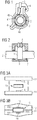
- FIG. 1 shows an exemplary sensor assembly comprising a tube 2 with a liquid and a flexible measuring head 1 wound around this tube, which in FIGS. 3A, 3B is explained in more detail.
- the measuring head 1 is arranged between the tube and a holder 4.
- the measuring head 1 is thermally coupled to the tube 2 in a relatively large-area coupling region.
- the holder 4 can be in one piece, z. B. be executed as a clamp.
- the holder 4 is preferably hinged.
- a hinge device 6 is provided which connects parts 4a, 4b of the holder 4 together.
- Hinge device 6 shown represents a bulge of the lateral surface of the holder 4. This hinge device is thus formed in one piece with the mutually hinged parts 4a, 4b of the holder 4.
- the parts of the holder 4 can also be designed as separable half shells, which are latched to each other.
- a cable feedthrough 5 is preferably in the form of a plug connection built-in.
- electrical leads are carried out, which include the conductor tracks 14, 15 or soldered or welded to these.
- the conductor tracks 14, 15 can z. B. flat wires.
- the holder 4 has a plurality of tube-facing projections 41, which are distributed around the circumference of the tube at a distance from each other. Between the measuring head 1, two successive projections and the cylindrical surface of the holder 4 which is essentially cylindrical in this variant, a closed cavity or air gap 3 is preferably formed. Between the measuring head 1 and the holder 4 a plurality of cavities or air gaps 3 are arranged. Such cavities can with a thermally insulating material such. B. foam at least partially filled.
- a respective seal 7 is arranged between both frontally arranged walls of the holder 4 and the tube 2. This is preferably a rubber ring.
- FIGS. 3A, 3B Measuring head 1 shown comprises a sensing element 10, two plastic films 11, 12 and conductor tracks 14, 15 for contacting the sensing element 10.
- the sensing element 10 comprises contacts 101, 102 and a thermistor layer 103 arranged between them.
- FIG. 3A a variant is presented, in which the conductor tracks 14, 15 are attached to the surface of these films prior to joining the films 11, 12. Alternatively, they can first be attached to the sensing element 10 and then welded together with this between the films 11, 12.
- FIG. 3B is a between the films 11, 12 welded sensing element 10 shown in a cross section perpendicular to the longitudinal direction of the measuring head 1.
- sensing elements 10 these are preferably distributed sequentially in the circumferential direction.
- the design of the measuring head and in particular the wiring of the sensing element 10 may be arbitrary in principle.
- a sensing element 10 is shown with SMD contacts on a major surface -. B. bottom - the sensing element are arranged.
- the conductor tracks 14, 15 connected to SMD contacts of the sensing element are arranged in a common position.
- plastic films 11, 12 can be replaced by the film composites 511, 512 explained below.
- FIGS. 4, 5 show various views of a sensor assembly having a first composite film 511, a metal layer arranged thereon with structured therein tracks 14, 15 and a sensing element 10 having disposed on its underside surface mount terminals 101, 102.
- a second film composite 512 is laminated, which also bears against the side surfaces of the sensing element and is sealed on all sides with the top of the first composite film 511.
- the second film composite 512 also covers the interconnects 14, 15 that are electrically connected to the sensing element 10.
- the first composite film 511 comprises a dielectric layer, e.g. B. the sub-layer 111 in FIG. 4 , and is z. B. a Cu-clad polyimide film, wherein the etched copper layer with the polyimide film z. B. by means of an in FIG. 4 shown adhesive layer 115 is firmly connected.
- the partial layers 111, 115 and the printed conductors 14, 15 together form a flexible composite.
- the adhesive layer 115 can be dispensed with.
- the second composite film 512 comprises a dielectric layer, e.g. B. the sub-layer 122 in FIG. 4 , On the underside of the sub-layer 122, an adhesive layer 124 is arranged, which ensures the adhesion between the sub-layer 122 and the top of the first film composite 511 or the surface of the sensing element 10 facing the second film composite 512.
- the partial layers 122, 124 together form a flexible composite.
- the structured metal layer with the conductor tracks 14, 15 is arranged on the upper side of the first film composite 511.
- FIG. 6 a variant is presented, in which the structured metal layer is arranged between two dielectric partial layers 111 and 112.
- the leading to the sensing element electrical leads 14, 15 are hidden inside the first composite film 511.
- the hidden tracks 14, 15 are externally via vertical electrical connections - the vias 140 - contacted.
- the plated-through holes 140 are firmly connected to the outer terminals 101, 102 of the sensing element 10.
- the uppermost or outwardly facing partial layer of the second composite film 512 is formed by an electromagnetically shielding partial layer 123, for example a copper layer.
- the lowermost or outwardly facing partial layer of the first composite film 511 is formed by an electromagnetically shielding sub-layer 110, for example a copper layer.
- FIG. 5 The top view on the in FIG. 4 or 6 shown sensor assembly is in FIG. 5 to see.
- the hidden tracks 14, 15 and the outer terminals 101, 102 of the sensing element 10 are shown by dashed lines.
- the design of the sensor arrangement is not limited to the technical features explained above or the shape and spatial arrangement of elements of the sensor arrangement shown in the figures.
- the soldering is replaced by a welded joint or a connector, and vice versa.
- Plug-connected solutions for the implementation of electrical leads include standardized mating connector.
Landscapes
- Physics & Mathematics (AREA)
- General Physics & Mathematics (AREA)
- Measuring Temperature Or Quantity Of Heat (AREA)
Claims (9)
- Ensemble de capteur servant à mesurer la température sur un tube et présentant une tête aplatie de mesure (1) et un support (4) qui convient pour entourer le tube (2) de telle sorte que la tête de mesure (1) soit disposée entre le support (4) et le tube (2),
la tête de mesure (1) comportant un ensemble formé d'au moins deux feuilles souples (11, 12) en matière synthétique entre lesquelles est disposé au moins un élément sensible (10) prévu pour saisir la température du tube (2),
l'élément sensible (10) comportant des contacts (101, 102) entre lesquels est disposée une couche (103) de thermistor,
la tête de mesure (1) comportant des pistes métalliques conductrices (14, 15) aptes à assurer le contact avec l'élément sensible (10) et disposées au moins en partie entre les deux feuilles (11, 12) en matière synthétique,
la tête de mesure (1) convenant pour toucher à plat au moins une partie de la surface du tube et à assurer le contact avec au moins 20 % de la périphérie du tube. - Ensemble de capteur selon la revendication 1, dans lequel la tête de mesure (1) convient pour être en contact avec au moins 50 % de la périphérie du tube.
- Ensemble de capteur selon les revendications 1 ou 2, dans lequel la tête de mesure (1) convient pour être repoussée par le support (4) contre le tube (2) ou pour être fixée sur le tube par collage.
- Ensemble de capteur selon la revendication 3, dans lequel le support (4) présente des saillies (41) en contact avec la tête de mesure (1), les parties du support (4) situées à l'extérieur des saillies étant situées à distance de la tête de mesure (1).
- Ensemble de capteur selon les revendications 3 ou 4, dans lequel le support (4) peut être rabattu autour du tube (2).
- Ensemble de capteur selon l'une des revendications 3 à 5, dans lequel le support (4) présente un bombement rabattable (6) prévu comme charnière.
- Ensemble de capteur selon l'une des revendications 3 à 6, dans lequel une cavité dans laquelle la tête de mesure (1) est disposée est prévue entre le support (4) et le tube (2), un joint d'étanchéité assurant l'étanchéité de la cavité étant disposé entre le support (4) et le tube (2).
- Ensemble de capteur selon l'une des revendications 3 à 7, dans lequel le support (4) comporte au moins une couche d'un matériau thermiquement isolant.
- Ensemble de capteur selon l'une des revendications 3 à 7, dans lequel le support (4) comporte au moins une couche d'un matériau poreux.
Applications Claiming Priority (2)
| Application Number | Priority Date | Filing Date | Title |
|---|---|---|---|
| DE102006025179A DE102006025179A1 (de) | 2006-05-30 | 2006-05-30 | Sensoranordnung |
| PCT/DE2007/000899 WO2007137552A2 (fr) | 2006-05-30 | 2007-05-15 | Dispositif détecteur |
Publications (2)
| Publication Number | Publication Date |
|---|---|
| EP2024720A2 EP2024720A2 (fr) | 2009-02-18 |
| EP2024720B1 true EP2024720B1 (fr) | 2017-07-26 |
Family
ID=38537924
Family Applications (1)
| Application Number | Title | Priority Date | Filing Date |
|---|---|---|---|
| EP07722447.5A Ceased EP2024720B1 (fr) | 2006-05-30 | 2007-05-15 | Dispositif détecteur |
Country Status (4)
| Country | Link |
|---|---|
| US (1) | US7824101B2 (fr) |
| EP (1) | EP2024720B1 (fr) |
| DE (1) | DE102006025179A1 (fr) |
| WO (1) | WO2007137552A2 (fr) |
Families Citing this family (19)
| Publication number | Priority date | Publication date | Assignee | Title |
|---|---|---|---|---|
| DE102004047725A1 (de) * | 2004-09-30 | 2006-04-06 | Epcos Ag | Sensorvorrichtung |
| BRPI0621812A2 (pt) * | 2006-06-13 | 2012-09-18 | Carrier Corp | tampa para um sensor de temperatura |
| DE102008029192A1 (de) | 2008-03-13 | 2009-09-24 | Epcos Ag | Fühler zum Erfassen einer physikalischen Größe und Verfahren zur Herstellung des Fühlers |
| JP5179295B2 (ja) * | 2008-08-27 | 2013-04-10 | 株式会社パイオラックス | 温度センサの取付装置 |
| JP5455454B2 (ja) * | 2009-06-08 | 2014-03-26 | 矢崎総業株式会社 | 簡便固定機能付き温度センサとそれの搭載された電池パック送風用エアダクト |
| DK2312288T3 (da) * | 2009-10-16 | 2013-02-18 | Jumo Gmbh & Co Kg | Temperatursensor med printplade med flere lag |
| US9146172B2 (en) * | 2011-01-03 | 2015-09-29 | Sentinel Hydrosolutions, Llc | Non-invasive thermal dispersion flow meter with chronometric monitor for fluid leak detection |
| US11608618B2 (en) | 2011-01-03 | 2023-03-21 | Sentinel Hydrosolutions, Llc | Thermal dispersion flow meter with fluid leak detection and freeze burst prevention |
| US11814821B2 (en) | 2011-01-03 | 2023-11-14 | Sentinel Hydrosolutions, Llc | Non-invasive thermal dispersion flow meter with fluid leak detection and geo-fencing control |
| DE102012108388A1 (de) | 2012-09-10 | 2014-03-13 | Endress + Hauser Wetzer Gmbh + Co. Kg | Temperaturmessvorrichtung zur Bestimmung der Temperatur an der Oberfläche einer Rohrleitung |
| JP6203076B2 (ja) * | 2014-02-19 | 2017-09-27 | 三菱電機株式会社 | サーミスタ取り付け構造、サーミスタ引き出し方法および空気調和機 |
| EP3067671A1 (fr) * | 2015-03-13 | 2016-09-14 | Flowgem Limited | Détermination de flux |
| EP3540329B1 (fr) | 2016-06-20 | 2021-04-28 | Bleckmann GmbH & Co. KG | Composant de système de chauffage fournissant une conception de capteur de température compact |
| CN106248238B (zh) * | 2016-09-27 | 2018-09-07 | 山东电力研究院 | 一种试验用热电偶固定器及安装方法 |
| US10386218B2 (en) * | 2016-11-22 | 2019-08-20 | Rota Yokogawa Gmbh & Co. Kg | Temperature measurement system for measuring the temperature of a tube and flowmeter comprising the temperature measurement system |
| US10220955B2 (en) * | 2017-01-05 | 2019-03-05 | Delta Air Lines, Inc. | Non-invasive and predictive health monitoring of an aircraft system |
| DE102017116533A1 (de) * | 2017-07-21 | 2019-01-24 | Tdk Electronics Ag | Anlegetemperaturmessfühler |
| US11287330B2 (en) * | 2018-08-14 | 2022-03-29 | Watlow Electric Manufacturing Company | Low profile surface temperature sensor |
| DE102021115573A1 (de) | 2021-06-16 | 2022-12-22 | Tdk Electronics Ag | Anordnung zum Schutz einer Sonsorvorrichtung |
Citations (1)
| Publication number | Priority date | Publication date | Assignee | Title |
|---|---|---|---|---|
| DE20208698U1 (de) * | 2002-06-05 | 2002-09-19 | Clauß, Ulrich, Dr.-Ing., 08297 Zwönitz | Temperatur-Anlegesensor |
Family Cites Families (16)
| Publication number | Priority date | Publication date | Assignee | Title |
|---|---|---|---|---|
| US3022478A (en) * | 1959-09-11 | 1962-02-20 | Engelhard Ind Inc | Resistance temperature sensing device |
| US3874239A (en) * | 1974-03-04 | 1975-04-01 | Thermo Couple Prod Co | Surface thermocouple |
| DE8329408U1 (de) * | 1983-10-12 | 1984-01-12 | Gossen Gmbh, 8520 Erlangen | Befestigungsvorrichtung fuer sensoren |
| GB2164150A (en) * | 1984-09-07 | 1986-03-12 | Emerson Electric Co | Temperature responsive actuating elements |
| US4971452A (en) * | 1988-02-05 | 1990-11-20 | Finney Philip F | RTD assembly |
| DE9305896U1 (de) * | 1993-04-20 | 1993-06-17 | Soyck, Gerno, 5884 Halver | Magnetfeldsensor für zugankerlose Arbeitszylinder |
| FR2737007B1 (fr) * | 1995-07-18 | 1997-09-19 | Elf Antar France | Dispositif de mesure de la temperature d'une paroi chaude |
| US7090658B2 (en) * | 1997-03-03 | 2006-08-15 | Medical Solutions, Inc. | Temperature sensing device for selectively measuring temperature at desired locations along an intravenous fluid line |
| EP1056994B1 (fr) * | 1998-02-05 | 2001-08-01 | Dr. E. Horn GmbH Messgerätefabrik | Thermoelement et dispositif de mesure pour mesurer sans contact une temperature sur des pieces de machines en mouvement |
| DE29905700U1 (de) * | 1999-03-27 | 1999-06-24 | Festo AG & Co, 73734 Esslingen | Sensoranordnung |
| DE10029186C2 (de) * | 2000-06-19 | 2002-04-25 | Heraeus Electro Nite Int | Temperatur-Messvorrichtung |
| DE10250196B4 (de) * | 2002-10-28 | 2007-10-11 | Siemens Ag | Detektor für einen Röntgen-Computertomograph |
| DE10358778B4 (de) * | 2003-01-15 | 2014-04-24 | Behr Gmbh & Co. Kg | Anordnung zur Temperaturmessung und Temperatursensor |
| DE10314705B3 (de) * | 2003-03-31 | 2004-07-01 | Heraeus Sensor Technology Gmbh | Vorrichtung zur Bestimmung der Temperatur eines strömenden Mediums in einer Rohr- oder Schlauchleitung |
| DE102004010713B4 (de) | 2004-03-04 | 2006-02-02 | Epcos Ag | Flexibler Sensor mit Thermistor |
| DE102004047725A1 (de) * | 2004-09-30 | 2006-04-06 | Epcos Ag | Sensorvorrichtung |
-
2006
- 2006-05-30 DE DE102006025179A patent/DE102006025179A1/de not_active Ceased
-
2007
- 2007-05-15 WO PCT/DE2007/000899 patent/WO2007137552A2/fr not_active Ceased
- 2007-05-15 EP EP07722447.5A patent/EP2024720B1/fr not_active Ceased
-
2008
- 2008-11-25 US US12/323,061 patent/US7824101B2/en not_active Expired - Fee Related
Patent Citations (1)
| Publication number | Priority date | Publication date | Assignee | Title |
|---|---|---|---|---|
| DE20208698U1 (de) * | 2002-06-05 | 2002-09-19 | Clauß, Ulrich, Dr.-Ing., 08297 Zwönitz | Temperatur-Anlegesensor |
Also Published As
| Publication number | Publication date |
|---|---|
| US20090135882A1 (en) | 2009-05-28 |
| WO2007137552A2 (fr) | 2007-12-06 |
| WO2007137552A3 (fr) | 2008-03-06 |
| DE102006025179A1 (de) | 2007-12-06 |
| US7824101B2 (en) | 2010-11-02 |
| EP2024720A2 (fr) | 2009-02-18 |
Similar Documents
| Publication | Publication Date | Title |
|---|---|---|
| EP2024720B1 (fr) | Dispositif détecteur | |
| US8523432B2 (en) | Thermally isolated temperature sensor | |
| EP2282179B1 (fr) | Procédé de fabrication d'une sonde de température | |
| DE10031124C2 (de) | Sensor zur Temperaturerfassung eines Fluids | |
| EP3230704B2 (fr) | Sonde de temperature | |
| DE10029186C2 (de) | Temperatur-Messvorrichtung | |
| EP2339307B1 (fr) | Dispositif de mesure de température | |
| WO2014037257A2 (fr) | Dispositif de mesure de température pour déterminer la température à la surface d'une canalisation | |
| EP2370798A1 (fr) | Capteur de température, en particulier pour un turbocompresseur | |
| DE102016105949A1 (de) | Nicht-intrusive Temperaturmessvorrichtung | |
| US20170191879A1 (en) | Temperature sensors with integrated sensing components | |
| DE102018129379B4 (de) | Temperatursensor | |
| US6590403B1 (en) | Material regression sensor | |
| DE102009028848A1 (de) | Aufbau und Herstellungsverfahrens eines Sensors eines thermischen Durchflussmessgeräts | |
| DE102012204817B4 (de) | Temperatursensor | |
| US11009401B2 (en) | Dual-sensor waterproof temperature monitoring probe and associated systems and methods | |
| EP2690417B1 (fr) | Répartiteur électronique de coûts de chauffage avec capteur de température ambiante | |
| DE10358778B4 (de) | Anordnung zur Temperaturmessung und Temperatursensor | |
| EP2732254A2 (fr) | Dispositif capteur de mesure haute température | |
| EP1982153B1 (fr) | Thermometre a resistance | |
| EP4515191B1 (fr) | Agencement de capteur pour une utilisation avec un article, de préférence avec un guide de milieu | |
| DE102011083240A1 (de) | Temperatursensor | |
| JPH0569467B2 (fr) | ||
| DE102007039935A1 (de) | Vorrichtung zur Bestimmung und/oder Überwachung einer Prozess- größe | |
| DE202005015987U1 (de) | Temperaturfühler |
Legal Events
| Date | Code | Title | Description |
|---|---|---|---|
| PUAI | Public reference made under article 153(3) epc to a published international application that has entered the european phase |
Free format text: ORIGINAL CODE: 0009012 |
|
| 17P | Request for examination filed |
Effective date: 20081031 |
|
| AK | Designated contracting states |
Kind code of ref document: A2 Designated state(s): AT BE BG CH CY CZ DE DK EE ES FI FR GB GR HU IE IS IT LI LT LU LV MC MT NL PL PT RO SE SI SK TR |
|
| AX | Request for extension of the european patent |
Extension state: AL BA HR MK RS |
|
| DAX | Request for extension of the european patent (deleted) | ||
| RBV | Designated contracting states (corrected) |
Designated state(s): DE FR GB |
|
| 17Q | First examination report despatched |
Effective date: 20101217 |
|
| GRAP | Despatch of communication of intention to grant a patent |
Free format text: ORIGINAL CODE: EPIDOSNIGR1 |
|
| INTG | Intention to grant announced |
Effective date: 20170322 |
|
| GRAS | Grant fee paid |
Free format text: ORIGINAL CODE: EPIDOSNIGR3 |
|
| GRAA | (expected) grant |
Free format text: ORIGINAL CODE: 0009210 |
|
| AK | Designated contracting states |
Kind code of ref document: B1 Designated state(s): DE FR GB |
|
| REG | Reference to a national code |
Ref country code: GB Ref legal event code: FG4D Free format text: NOT ENGLISH |
|
| REG | Reference to a national code |
Ref country code: DE Ref legal event code: R096 Ref document number: 502007015771 Country of ref document: DE |
|
| RAP2 | Party data changed (patent owner data changed or rights of a patent transferred) |
Owner name: EPCOS AG |
|
| REG | Reference to a national code |
Ref country code: DE Ref legal event code: R097 Ref document number: 502007015771 Country of ref document: DE |
|
| PLBE | No opposition filed within time limit |
Free format text: ORIGINAL CODE: 0009261 |
|
| STAA | Information on the status of an ep patent application or granted ep patent |
Free format text: STATUS: NO OPPOSITION FILED WITHIN TIME LIMIT |
|
| 26N | No opposition filed |
Effective date: 20180430 |
|
| REG | Reference to a national code |
Ref country code: DE Ref legal event code: R082 Ref document number: 502007015771 Country of ref document: DE Representative=s name: EPPING HERMANN FISCHER PATENTANWALTSGESELLSCHA, DE Ref country code: DE Ref legal event code: R081 Ref document number: 502007015771 Country of ref document: DE Owner name: TDK ELECTRONICS AG, DE Free format text: FORMER OWNER: EPCOS AG, 81669 MUENCHEN, DE |
|
| GBPC | Gb: european patent ceased through non-payment of renewal fee |
Effective date: 20180515 |
|
| PG25 | Lapsed in a contracting state [announced via postgrant information from national office to epo] |
Ref country code: FR Free format text: LAPSE BECAUSE OF NON-PAYMENT OF DUE FEES Effective date: 20180531 Ref country code: GB Free format text: LAPSE BECAUSE OF NON-PAYMENT OF DUE FEES Effective date: 20180515 |
|
| P01 | Opt-out of the competence of the unified patent court (upc) registered |
Effective date: 20230521 |
|
| PGFP | Annual fee paid to national office [announced via postgrant information from national office to epo] |
Ref country code: DE Payment date: 20240522 Year of fee payment: 18 |
|
| REG | Reference to a national code |
Ref country code: DE Ref legal event code: R119 Ref document number: 502007015771 Country of ref document: DE |
|
| PG25 | Lapsed in a contracting state [announced via postgrant information from national office to epo] |
Ref country code: DE Free format text: LAPSE BECAUSE OF NON-PAYMENT OF DUE FEES Effective date: 20251202 |