EP2025444B1 - Dispositif de serrage à faible traction destiné au serrage dans des forages et des contours internes d'objets - Google Patents
Dispositif de serrage à faible traction destiné au serrage dans des forages et des contours internes d'objets Download PDFInfo
- Publication number
- EP2025444B1 EP2025444B1 EP08162450A EP08162450A EP2025444B1 EP 2025444 B1 EP2025444 B1 EP 2025444B1 EP 08162450 A EP08162450 A EP 08162450A EP 08162450 A EP08162450 A EP 08162450A EP 2025444 B1 EP2025444 B1 EP 2025444B1
- Authority
- EP
- European Patent Office
- Prior art keywords
- clamping
- pull
- insert
- clamping device
- clamping element
- Prior art date
- Legal status (The legal status is an assumption and is not a legal conclusion. Google has not performed a legal analysis and makes no representation as to the accuracy of the status listed.)
- Active
Links
Images


Classifications
-
- B—PERFORMING OPERATIONS; TRANSPORTING
- B23—MACHINE TOOLS; METAL-WORKING NOT OTHERWISE PROVIDED FOR
- B23Q—DETAILS, COMPONENTS, OR ACCESSORIES FOR MACHINE TOOLS, e.g. ARRANGEMENTS FOR COPYING OR CONTROLLING; MACHINE TOOLS IN GENERAL CHARACTERISED BY THE CONSTRUCTION OF PARTICULAR DETAILS OR COMPONENTS; COMBINATIONS OR ASSOCIATIONS OF METAL-WORKING MACHINES, NOT DIRECTED TO A PARTICULAR RESULT
- B23Q1/00—Members which are comprised in the general build-up of a form of machine, particularly relatively large fixed members
- B23Q1/0063—Connecting non-slidable parts of machine tools to each other
- B23Q1/0081—Connecting non-slidable parts of machine tools to each other using an expanding clamping member insertable in a receiving hole
- B23Q1/009—Connecting non-slidable parts of machine tools to each other using an expanding clamping member insertable in a receiving hole the receiving hole being cylindrical or conical
-
- B—PERFORMING OPERATIONS; TRANSPORTING
- B23—MACHINE TOOLS; METAL-WORKING NOT OTHERWISE PROVIDED FOR
- B23Q—DETAILS, COMPONENTS, OR ACCESSORIES FOR MACHINE TOOLS, e.g. ARRANGEMENTS FOR COPYING OR CONTROLLING; MACHINE TOOLS IN GENERAL CHARACTERISED BY THE CONSTRUCTION OF PARTICULAR DETAILS OR COMPONENTS; COMBINATIONS OR ASSOCIATIONS OF METAL-WORKING MACHINES, NOT DIRECTED TO A PARTICULAR RESULT
- B23Q3/00—Devices holding, supporting, or positioning work or tools, of a kind normally removable from the machine
- B23Q3/18—Devices holding, supporting, or positioning work or tools, of a kind normally removable from the machine for positioning only
- B23Q3/183—Centering devices
-
- Y—GENERAL TAGGING OF NEW TECHNOLOGICAL DEVELOPMENTS; GENERAL TAGGING OF CROSS-SECTIONAL TECHNOLOGIES SPANNING OVER SEVERAL SECTIONS OF THE IPC; TECHNICAL SUBJECTS COVERED BY FORMER USPC CROSS-REFERENCE ART COLLECTIONS [XRACs] AND DIGESTS
- Y10—TECHNICAL SUBJECTS COVERED BY FORMER USPC
- Y10T—TECHNICAL SUBJECTS COVERED BY FORMER US CLASSIFICATION
- Y10T24/00—Buckles, buttons, clasps, etc.
- Y10T24/44—Clasp, clip, support-clamp, or required component thereof
- Y10T24/44017—Clasp, clip, support-clamp, or required component thereof with specific mounting means for attaching to rigid or semirigid supporting structure or structure-to-be-secured
- Y10T24/44026—Clasp, clip, support-clamp, or required component thereof with specific mounting means for attaching to rigid or semirigid supporting structure or structure-to-be-secured for cooperating with aperture in supporting structure or structure-to-be-secured
-
- Y—GENERAL TAGGING OF NEW TECHNOLOGICAL DEVELOPMENTS; GENERAL TAGGING OF CROSS-SECTIONAL TECHNOLOGIES SPANNING OVER SEVERAL SECTIONS OF THE IPC; TECHNICAL SUBJECTS COVERED BY FORMER USPC CROSS-REFERENCE ART COLLECTIONS [XRACs] AND DIGESTS
- Y10—TECHNICAL SUBJECTS COVERED BY FORMER USPC
- Y10T—TECHNICAL SUBJECTS COVERED BY FORMER US CLASSIFICATION
- Y10T24/00—Buckles, buttons, clasps, etc.
- Y10T24/44—Clasp, clip, support-clamp, or required component thereof
- Y10T24/44034—Dissociable gripping members
-
- Y—GENERAL TAGGING OF NEW TECHNOLOGICAL DEVELOPMENTS; GENERAL TAGGING OF CROSS-SECTIONAL TECHNOLOGIES SPANNING OVER SEVERAL SECTIONS OF THE IPC; TECHNICAL SUBJECTS COVERED BY FORMER USPC CROSS-REFERENCE ART COLLECTIONS [XRACs] AND DIGESTS
- Y10—TECHNICAL SUBJECTS COVERED BY FORMER USPC
- Y10T—TECHNICAL SUBJECTS COVERED BY FORMER US CLASSIFICATION
- Y10T24/00—Buckles, buttons, clasps, etc.
- Y10T24/44—Clasp, clip, support-clamp, or required component thereof
- Y10T24/44068—Clasp, clip, support-clamp, or required component thereof having gripping member actuated by fluid force
-
- Y—GENERAL TAGGING OF NEW TECHNOLOGICAL DEVELOPMENTS; GENERAL TAGGING OF CROSS-SECTIONAL TECHNOLOGIES SPANNING OVER SEVERAL SECTIONS OF THE IPC; TECHNICAL SUBJECTS COVERED BY FORMER USPC CROSS-REFERENCE ART COLLECTIONS [XRACs] AND DIGESTS
- Y10—TECHNICAL SUBJECTS COVERED BY FORMER USPC
- Y10T—TECHNICAL SUBJECTS COVERED BY FORMER US CLASSIFICATION
- Y10T24/00—Buckles, buttons, clasps, etc.
- Y10T24/45—Separable-fastener or required component thereof [e.g., projection and cavity to complete interlock]
-
- Y—GENERAL TAGGING OF NEW TECHNOLOGICAL DEVELOPMENTS; GENERAL TAGGING OF CROSS-SECTIONAL TECHNOLOGIES SPANNING OVER SEVERAL SECTIONS OF THE IPC; TECHNICAL SUBJECTS COVERED BY FORMER USPC CROSS-REFERENCE ART COLLECTIONS [XRACs] AND DIGESTS
- Y10—TECHNICAL SUBJECTS COVERED BY FORMER USPC
- Y10T—TECHNICAL SUBJECTS COVERED BY FORMER US CLASSIFICATION
- Y10T24/00—Buckles, buttons, clasps, etc.
- Y10T24/45—Separable-fastener or required component thereof [e.g., projection and cavity to complete interlock]
- Y10T24/45005—Separable-fastener or required component thereof [e.g., projection and cavity to complete interlock] with third detached member completing interlock [e.g., hook type]
Definitions
- the invention relates to a Niederzugspannvorraum for bores clamping objects with a clamping unit having a clamping element and a drive piston.
- Such a Niederyakspannvoroplasty is from the EP 0 785 049 A1 known.
- Such Niederyakspannement serve for internal clamping of objects in holes. For example, workpieces or pallets to be machined can be tensioned in this way.
- That in the EP 0 785 049 A1 shown Niederyakspannelement has a clamping element which is integrally connected to an output piston for actuating the clamping element.
- the DE 10 2004 006 213 B3 shows a Niederyakspannvorraum, with the objects can be clamped to a defined fixed point or zero point. For this purpose, the clamping element is guided largely free of play in the clamping unit. But there are also Niederyakspannvorraumen in which the clamping elements allow compensation, so that tolerances of the exciting inner bore can be compensated. Such compensation options are partially provided 1-dimensional, so that the clamping elements have in one direction game. But there are also Niederyakspannetti that allow a 2-dimensional compensation.
- the problem underlying the invention is to provide a Niederzugspannvorraum, which can be easily adapted to the needs of the different clamping methods.
- the invention Niederzugspannvorraum characterized in that the clamping element is arranged in a modular interchangeable clamping insert by the drive piston is arranged parallel to the clamping element and mechanically coupled by means of a pin with the clamping insert.
- the same clamping unit with modular exchangeable clamping inserts can be used in the Niederzugspannvorraum with the invention features.
- the desired clamping technology can be achieved.
- Another advantage of the invention is an improved sealing of the system against the ingress of dirt and easy maintenance. Due to the mechanical coupling of the drive piston with the clamping insert by means of the pin, this coupling can be easily disassembled and set again after changing the clamping insert. Since the piston movement and the clamping movement of the clamping insert are parallel to each other, a particularly slim design can be achieved.
- the coupling between the working piston and the clamping element is preferably carried out in a form-fitting manner.
- the drive piston is acted upon hydraulically.
- a drive piston can be reliably and easily generate high clamping forces.
- the drive piston is arranged in a further development parallel to the clamping insert.
- a development of the invention is characterized by several different clamping inserts.
- the appropriate clamping insert can be prepared for every clamping technique, so that the modular exchange can be carried out quickly and comfortably.
- the clamping element is firmly connected to the clamping insert.
- the so-called zero point margins results simply and reliably.
- the clamping element is movably connected to the clamping insert.
- the clamping element can be pivotally connected to the clamping insert about an axis perpendicular to the clamping direction. This results in a simple and convenient compensation option for the position of the clamping hole during clamping.
- An advantageous embodiment of the invention is characterized in that the clamping insert is designed for a return to a starting position when releasing the voltage. In this way, a compensation during clamping on the one hand possible, with the clamping insert for arranging the workpiece on the Niederzugspannvorraum is always at the starting position. In this way, the placement of a workpiece on the Niederzugspannvorraum is facilitated.
- the clamping element has a clamping ring and a pull rod.
- the tensioning element preferably also has a conical piece which has a cone assigned to the tensioning ring. In this way can be widened by pulling down the pull rod of the clamping ring by means of the cone for clamping.
- a bearing is provided for the cone piece. The bearing, for example, ensure a tight fit of the cone piece. In this way, the zero point voltage is advantageously supported.
- the bearing allows the cone piece a compensation movement.
- the bearing can allow the cone piece a 1-dimensional or 2-dimensional compensation movement. In conjunction with the movable connection between the clamping element and the clamping insert, this results in a simple, effective and yet reliable compensation device with reliable clamping action.
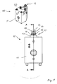
- Fig. 1 shows in the upper part of a perspective plan view of a Niederzugspannvorraum 10 as a first embodiment with the features of the invention.
- Fig. 1 a front view of the Niederzugspannvorraum 10.
- the Niederyakspannvorraum 10 a clamping unit 11 with a clamping element 12 disposed therein.
- the clamping element 12 has a pull rod 13, to which a nut 14 is screwed.
- a clamping ring 15 is arranged, which cooperates in a known manner with a cone insert 16 for clamping.
- the cone insert 16 in turn is arranged for clamping in a bearing 17.
- a bore 18 is indicated in broken lines in a workpiece, not shown.
- the pull rod 13 For clamping in the bore 18, the pull rod 13 is moved in a known manner in the figure down. When striking the cone insert 16 in the bearing 17 of the cone insert 16 spreads the clamping ring 15 apart. Due to the spreading apart of the clamping ring 15 in the bore 18, the workpiece is then securely clamped.
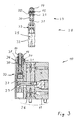
- Fig. 2 shows the section AA of Fig. 1 , Also, in the upper part of Fig. 2 the clamping element 12 shown in a detailed view. As the figure shows, the clamping element 12 is formed as part of a clamping insert 19. In the detailed representation of the clamping insert 19 can also be seen that the cone insert 16 facing the clamping ring 15 has a cone 20 for spreading the clamping ring 15. In addition, in a groove of the cone insert 16, a sealing ring 21, the cone insert 16 is arranged surrounding.
- the clamping insert 19 also has a clamping body 22 with a thread 23, which is arranged with a thread on the side facing away from the nut 14 end of the tie rod 13 thread 24 is engaged.
- the pull rod 13 is connected by means of the thread 23, 24 rigidly connected to the clamping body 22.
- clamping body 22 transverse to the pull rod 13 has a bore 25.
- a drive piston 26 is arranged in the clamping unit 11, which is acted upon in a known manner with a hydraulic fluid.
- the drive piston 26 is arranged parallel to the clamping insert 19 and connected to the clamping body 22.
- the drive piston 26 is mechanically, in particular form-fitting, connected to the clamping body 22.
- the drive piston 26 is connected by means of a pin 27 with the clamping body 22.
- the pull rod 13 is fixedly connected to the clamping body 22.
- the cone insert 16 is fixedly mounted in the bearing 17 and the pull rod 13 is guided largely free of play in the cone insert 16. In this way, a so-called zero point voltage is realized by means of the clamping insert 19 and the bearing 17, in which the bore 18 is tensioned largely free of play in a defined position to the Niederzugspannvorraum 10.
- Fig. 3 shows a second embodiment of the Niederzugspannvorraum 10 with the features of the invention.
- the same elements bear the same reference numbers.
- a clamping insert 28 is inserted into the clamping unit 11 instead of the clamping insert 19.
- the clamping insert 28 is in the upper part of Fig. 3 to be seen in detail.
- the clamping insert 28 has a clamping element 29 similar to the clamping element 12.
- the clamping element 29 has a taper insert 30 similar to the cone insert 16, a tie rod 31 and a clamping body 32.
- the tie rod 31 is movable in this embodiment with the Clamping 32 connected.
- the drawbar 31 is connected by means of an articulated connection 33 with the clamping body 32.
- the clamping unit 11 has a bearing 34 similar to the bearing 17.
- the bearing 34 differs from the bearing 17 in that a compensating movement of the drawbar 31 for clamping is possible.
- the connection 33 and the combination of the cone insert 30 and the bearing 34 supports a pivoting movement of the drawbar 31 about a 33 arranged in the region of the connection transverse to the drawbar 31 axis, which is not shown in the figure and lies in the plane of the paper.
- Fig. 4 shows a further embodiment of a Niederzugspannvorraum 10 with the features of the invention.
- the clamping insert 35 essentially corresponds to the clamping inserts 19, 28.
- the clamping insert 35 has a clamping element 36 with a cone insert 37 and a pull rod 38 which is movably connected to a clamping body 39 by means of a connection 40.
- the drawbar 38 is gimbal connected to the clamping body 39. In this way, a free pivoting movement of the drawbar 38 to enable axes transverse to the clamping body 39 in the region of the connection 40.
- a similar movable connection can be achieved for example by a ball joint.
- the bearing 41 cooperates with the cone insert 37 and the tie rod 38 such that a compensating movement of the tie rod 38 for clamping according to the connection 40 in the form of a pivoting movement of the drawbar both in the paper plane also at right angles is possible.
Landscapes
- Engineering & Computer Science (AREA)
- Mechanical Engineering (AREA)
- Clamps And Clips (AREA)
- Jigs For Machine Tools (AREA)
- Hand Tools For Fitting Together And Separating, Or Other Hand Tools (AREA)
Claims (13)
- Dispositif de serrage à faible traction destiné au serrage pour forages ou alésages et des contours internes pour des objets à l'aide d'un ensemble de serrage (11) qui est muni d'un élément de serrage (12,29,36) et d'un piston d'actionnement (26) caractérisé en ce que l'élément de serrage (12,29,36) est constitué par un jeu modulaire interchangeable d'éléments de serrage (19,28,35) et que le piston d'actionnement (26) est disposé parallèlement à l'élément (12,29,36), et est accouplé mécaniquement au moyen d'une tige-goupille (27) avec le jeu interchangeable d'éléments de serrage (19, 28,35).
- Dispositif de serrage à faible traction destiné au serrage selon la revendication 1, caractérisé en ce que le piston d'actionnement (26) est ajusté et accouplé au jeu modulaire interchangeable d'éléments de serrage (19, 28,35)
- Dispositif de serrage à faible traction destiné au serrage selon la revendication 1 ou 2 caractérisé en ce que le piston d'actionnement (26) est mû hydrauliquement.
- Dispositif de serrage à faible traction destiné au serrage selon l'une des revendications 1 à 3, caractérisé par plusieurs éléments de serrage (19, 28,35) et de différentes sortes.
- Dispositif de serrage à faible traction destiné au serrage selon l'une des revendications 1 à 4 caractérisé en ce que l'élément de serrage (12) est solidarisé et fixé à l'élément de serrage (19).
- Dispositif de serrage à faible traction destiné au serrage selon l'une des revendications précédentes, caractérisé en ce que l'élément de serrage (29, 36) est articulé mobile et solidaire du jeu interchangeable d'éléments de serrage (28,35).
- Dispositif de serrage à faible traction destiné au serrage selon la revendication 6 caractérisé en ce que l'élément de serrage (29,36) est pivotant pour un positionnement axial et à angle droit par rapport au jeu interchangeable d'éléments de serrage (28,35).
- Dispositif de serrage à faible traction destiné au serrage selon l'une des revendications précédentes caractérisé en ce que le jeu modulaire interchangeable d'éléments de serrage (28,35) est configuré de manière telle à permettre un positionnement de dégagement lors de la chute de la pression motrice.
- Dispositif de serrage à faible traction destiné au serrage selon l'une des revendications précédentes caractérisé en ce que l'élément de serrage (12,29,36) est muni d'une bague de serrage (15) et d'une tige de traction (13,31,38).
- Dispositif de serrage à faible traction destiné au serrage selon la revendication 9 caractérisé en ce que l'élément de serrage (12, 29,36) comporte un insert conique (16,30,37) muni d'une conicité (20) correspondant à celle de la bague de serrage (15).
- Dispositif de serrage à faible traction destiné au serrage selon la revendication 10 caractérisé en ce qu'un coussinet (17,34,41) est couplé au coussinet (16,30,37).
- Dispositif de serrage à faible traction destiné au serrage selon la revendication 11 caractérisé en ce que le coussinet (17) est la partie fixe de l'insert conique (16).
- Dispositif de serrage à faible traction destiné au serrage selon la revendication 12 caractérisé en ce que le coussinet (34, 41) de l'insert conique (30, 37) dispose d'une articulation et d'une mobilité mono ou bidimensionnelle.
Applications Claiming Priority (1)
| Application Number | Priority Date | Filing Date | Title |
|---|---|---|---|
| DE102007038656A DE102007038656A1 (de) | 2007-08-15 | 2007-08-15 | Niederzugspannvorrichtung zum Bohrungsspannen von Gegenständen |
Publications (2)
| Publication Number | Publication Date |
|---|---|
| EP2025444A1 EP2025444A1 (fr) | 2009-02-18 |
| EP2025444B1 true EP2025444B1 (fr) | 2010-06-23 |
Family
ID=39790355
Family Applications (1)
| Application Number | Title | Priority Date | Filing Date |
|---|---|---|---|
| EP08162450A Active EP2025444B1 (fr) | 2007-08-15 | 2008-08-15 | Dispositif de serrage à faible traction destiné au serrage dans des forages et des contours internes d'objets |
Country Status (4)
| Country | Link |
|---|---|
| US (1) | US8220114B2 (fr) |
| EP (1) | EP2025444B1 (fr) |
| AT (1) | ATE471785T1 (fr) |
| DE (2) | DE102007038656A1 (fr) |
Families Citing this family (7)
| Publication number | Priority date | Publication date | Assignee | Title |
|---|---|---|---|---|
| JP5346542B2 (ja) * | 2008-04-24 | 2013-11-20 | パスカルエンジニアリング株式会社 | クランプ装置 |
| DE102010013911B4 (de) * | 2010-04-01 | 2013-07-25 | Schunk Gmbh & Co. Kg Spann- Und Greiftechnik | Spannmodul, insbesondere Nullpunktspannmodul |
| JP6244089B2 (ja) * | 2012-11-30 | 2017-12-06 | 株式会社コスメック | クランプ装置 |
| DE102016005373A1 (de) | 2016-04-26 | 2017-10-26 | Westinghouse Electric Germany Gmbh | Spannvorrichtung |
| CN109129181A (zh) * | 2018-08-09 | 2019-01-04 | 柳州市钜诚科技有限公司 | 一种筒形铸件夹持工装 |
| DE102019120427B4 (de) * | 2019-07-29 | 2024-05-02 | Ludwig Ehrhardt Gmbh | Bohrungsspanner mit Rückstelleinrichtung |
| CN111761553B (zh) * | 2020-07-06 | 2023-07-25 | 温州大学 | 一种用于夹持人造骨骼的装置 |
Family Cites Families (12)
| Publication number | Priority date | Publication date | Assignee | Title |
|---|---|---|---|---|
| DE4020981A1 (de) | 1990-07-02 | 1992-01-16 | Pasquale Dipl Ing Cianci | Spannvorrichtung |
| DE29500115U1 (de) | 1995-01-05 | 1995-02-23 | Abb Reaktor Gmbh, 68167 Mannheim | Spannelement zum Festlegen in einer Bohrung eines Bauteiles |
| EP0785049B1 (fr) | 1996-01-15 | 2004-11-03 | Cianci, Pasquale, Dipl.-Ing | Table de support avec dispositif de serrage |
| JP3550010B2 (ja) * | 1997-12-24 | 2004-08-04 | 株式会社コスメック | クランプ装置 |
| JP2004223702A (ja) * | 2002-11-29 | 2004-08-12 | Kosmek Ltd | 位置決め装置 |
| JP4260488B2 (ja) * | 2003-01-07 | 2009-04-30 | 株式会社コスメック | 調心駆動機構およびその機構を備えた位置決め装置 |
| JP4311616B2 (ja) * | 2003-01-24 | 2009-08-12 | 株式会社コスメック | バネロック式クランプ装置 |
| WO2004067224A1 (fr) * | 2003-01-29 | 2004-08-12 | Kosmek Ltd. | Dispositif de fixation et systeme de fixation utilisant ce dispositif |
| DE10312192B3 (de) * | 2003-03-19 | 2004-08-05 | Hohenstein Vorrichtungsbau Und Spannsysteme Gmbh | System-Niederzugspanner |
| DE102004006213B3 (de) | 2004-02-07 | 2005-08-25 | Werkstückspanntechnik GmbH | Niederzug-Schnellspannvorrichtung |
| DE102004026187B4 (de) | 2004-05-28 | 2007-09-13 | Pasquale Cianci | Spannelement mit keilförmigen Spannflächen |
| DE102005009177A1 (de) * | 2005-02-17 | 2006-09-21 | Gerd Gladkowski | Multifunktionaler Spannturm |
-
2007
- 2007-08-15 DE DE102007038656A patent/DE102007038656A1/de not_active Withdrawn
-
2008
- 2008-08-11 US US12/189,256 patent/US8220114B2/en not_active Expired - Fee Related
- 2008-08-15 EP EP08162450A patent/EP2025444B1/fr active Active
- 2008-08-15 AT AT08162450T patent/ATE471785T1/de active
- 2008-08-15 DE DE502008000817T patent/DE502008000817D1/de active Active
Also Published As
| Publication number | Publication date |
|---|---|
| DE502008000817D1 (de) | 2010-08-05 |
| US8220114B2 (en) | 2012-07-17 |
| EP2025444A1 (fr) | 2009-02-18 |
| US20090044386A1 (en) | 2009-02-19 |
| DE102007038656A1 (de) | 2009-02-19 |
| ATE471785T1 (de) | 2010-07-15 |
Similar Documents
| Publication | Publication Date | Title |
|---|---|---|
| DE2302732A1 (de) | Einstellbare daempfungsvorrichtung | |
| EP1140400B1 (fr) | Outil a enlevement de copeaux pour usinage a vitesse elevee | |
| EP3875215B1 (fr) | Plaque de serrage à point zéro, machine-outil pourvue d'une telle plaque de serrage et dispositif de serrage | |
| DE202016008567U1 (de) | Mit einer Verankerungsvorrichtung versehene Bohrmaschine | |
| DE60122223T2 (de) | Werkzeugbaugruppe | |
| EP2025444A1 (fr) | Dispositif de serrage à faible traction destiné au serrage dans des forages et des contours internes d'objets | |
| DE602006000173T2 (de) | Biegevorrichtung für Biegemaschine | |
| DE8703979U1 (de) | Befestigungseinrichtung für Teile einer Fahrradlenkstange mit Einspannteilen, die zwei gelenkig miteinander verbundene Backenteile umfassen | |
| DE2258357A1 (de) | Grabemaschine | |
| WO2002031271A2 (fr) | Dispositif de fixation interchangeable d'une piece rapportee telle qu'une pelle, a une fleche de pelle ou a un vehicule | |
| DE2402054C2 (de) | Vorrichtung zum Festspannen von Werkstücken auf einer Aufspannplatte | |
| EP2998068B1 (fr) | Étau de centrage doté de mors a changement rapide | |
| DE3001805C2 (fr) | ||
| DE3432693A1 (de) | Supportkoerper | |
| EP2181806A2 (fr) | Dispositif de serrage | |
| DE10025077A1 (de) | Spannzwinge | |
| EP2881218B1 (fr) | Lunette destinée au soutien d'une pièce usinée | |
| DE3025156A1 (de) | Presse mit einem stanz- und/oder presswerkzeug | |
| EP2747929B1 (fr) | Outil pour usiner des pièces | |
| DE202007010794U1 (de) | Spanneinrichtung | |
| DE102020004165A1 (de) | Positionseinstellvorrichtung und Ultrapräzisions-Werkzeugmaschine | |
| DE3019348A1 (de) | Anbaudrehpflug | |
| DE2938208A1 (de) | Vorrichtung zum ankuppeln eines werkzeuges an den ausleger eines baggers | |
| DE9112470U1 (de) | Schaufel mit Unterschraubmessern | |
| EP4098092B1 (fr) | Système de changement rapide pour un véhicule |
Legal Events
| Date | Code | Title | Description |
|---|---|---|---|
| PUAI | Public reference made under article 153(3) epc to a published international application that has entered the european phase |
Free format text: ORIGINAL CODE: 0009012 |
|
| AK | Designated contracting states |
Kind code of ref document: A1 Designated state(s): AT BE BG CH CY CZ DE DK EE ES FI FR GB GR HR HU IE IS IT LI LT LU LV MC MT NL NO PL PT RO SE SI SK TR |
|
| AX | Request for extension of the european patent |
Extension state: AL BA MK RS |
|
| 17P | Request for examination filed |
Effective date: 20090818 |
|
| 17Q | First examination report despatched |
Effective date: 20090911 |
|
| AKX | Designation fees paid |
Designated state(s): AT DE FR GB IT |
|
| GRAP | Despatch of communication of intention to grant a patent |
Free format text: ORIGINAL CODE: EPIDOSNIGR1 |
|
| GRAS | Grant fee paid |
Free format text: ORIGINAL CODE: EPIDOSNIGR3 |
|
| GRAA | (expected) grant |
Free format text: ORIGINAL CODE: 0009210 |
|
| AK | Designated contracting states |
Kind code of ref document: B1 Designated state(s): AT DE FR GB IT |
|
| REF | Corresponds to: |
Ref document number: 502008000817 Country of ref document: DE Date of ref document: 20100805 Kind code of ref document: P |
|
| REG | Reference to a national code |
Ref country code: DE Ref legal event code: R096 Ref document number: 502008000817 Country of ref document: DE Effective date: 20100805 |
|
| PLBE | No opposition filed within time limit |
Free format text: ORIGINAL CODE: 0009261 |
|
| STAA | Information on the status of an ep patent application or granted ep patent |
Free format text: STATUS: NO OPPOSITION FILED WITHIN TIME LIMIT |
|
| 26N | No opposition filed |
Effective date: 20110324 |
|
| REG | Reference to a national code |
Ref country code: DE Ref legal event code: R097 Ref document number: 502008000817 Country of ref document: DE Effective date: 20110323 Ref country code: DE Ref legal event code: R097 Ref document number: 502008000817 Country of ref document: DE Effective date: 20110324 |
|
| REG | Reference to a national code |
Ref country code: DE Ref legal event code: R082 Ref document number: 502008000817 Country of ref document: DE Representative=s name: ZACCO DR. PETERS UND PARTNER, DE Ref country code: DE Ref legal event code: R082 Ref document number: 502008000817 Country of ref document: DE Representative=s name: TAPPE, UDO, DIPL.-PHYS. DR.RER.NAT., DE Ref country code: DE Ref legal event code: R082 Ref document number: 502008000817 Country of ref document: DE Representative=s name: ZACCO PATENTANWALTS- UND RECHTSANWALTSGESELLSC, DE |
|
| REG | Reference to a national code |
Ref country code: FR Ref legal event code: PLFP Year of fee payment: 9 |
|
| REG | Reference to a national code |
Ref country code: FR Ref legal event code: PLFP Year of fee payment: 10 |
|
| REG | Reference to a national code |
Ref country code: FR Ref legal event code: PLFP Year of fee payment: 11 |
|
| REG | Reference to a national code |
Ref country code: DE Ref legal event code: R082 Ref document number: 502008000817 Country of ref document: DE Representative=s name: TAPPE, UDO, DIPL.-PHYS. DR.RER.NAT., DE |
|
| P01 | Opt-out of the competence of the unified patent court (upc) registered |
Effective date: 20230515 |
|
| PGFP | Annual fee paid to national office [announced via postgrant information from national office to epo] |
Ref country code: DE Payment date: 20240831 Year of fee payment: 17 |
|
| PGFP | Annual fee paid to national office [announced via postgrant information from national office to epo] |
Ref country code: GB Payment date: 20240822 Year of fee payment: 17 |
|
| PGFP | Annual fee paid to national office [announced via postgrant information from national office to epo] |
Ref country code: FR Payment date: 20240823 Year of fee payment: 17 |
|
| PGFP | Annual fee paid to national office [announced via postgrant information from national office to epo] |
Ref country code: AT Payment date: 20240819 Year of fee payment: 17 |
|
| PGFP | Annual fee paid to national office [announced via postgrant information from national office to epo] |
Ref country code: IT Payment date: 20240830 Year of fee payment: 17 |
|
| REG | Reference to a national code |
Ref country code: DE Ref legal event code: R119 Ref document number: 502008000817 Country of ref document: DE |
|
| PG25 | Lapsed in a contracting state [announced via postgrant information from national office to epo] |
Ref country code: AT Free format text: LAPSE BECAUSE OF NON-PAYMENT OF DUE FEES Effective date: 20250815 |
|
| REG | Reference to a national code |
Ref country code: AT Ref legal event code: MM01 Ref document number: 471785 Country of ref document: AT Kind code of ref document: T Effective date: 20250815 |
|
| GBPC | Gb: european patent ceased through non-payment of renewal fee |
Effective date: 20250815 |