EP2025473A2 - Clé à chocs - Google Patents
Clé à chocs Download PDFInfo
- Publication number
- EP2025473A2 EP2025473A2 EP08162034A EP08162034A EP2025473A2 EP 2025473 A2 EP2025473 A2 EP 2025473A2 EP 08162034 A EP08162034 A EP 08162034A EP 08162034 A EP08162034 A EP 08162034A EP 2025473 A2 EP2025473 A2 EP 2025473A2
- Authority
- EP
- European Patent Office
- Prior art keywords
- hammer
- axial
- stop
- travel path
- travel
- Prior art date
- Legal status (The legal status is an assumption and is not a legal conclusion. Google has not performed a legal analysis and makes no representation as to the accuracy of the status listed.)
- Granted
Links
Images


Classifications
-
- B—PERFORMING OPERATIONS; TRANSPORTING
- B25—HAND TOOLS; PORTABLE POWER-DRIVEN TOOLS; MANIPULATORS
- B25B—TOOLS OR BENCH DEVICES NOT OTHERWISE PROVIDED FOR, FOR FASTENING, CONNECTING, DISENGAGING, OR HOLDING
- B25B21/00—Portable power-driven screw or nut setting or loosening tools; Attachments for drilling apparatus serving the same purpose
- B25B21/02—Portable power-driven screw or nut setting or loosening tools; Attachments for drilling apparatus serving the same purpose with means for imparting impact to screwdriver blade or nut socket
- B25B21/026—Impact clutches
-
- B—PERFORMING OPERATIONS; TRANSPORTING
- B25—HAND TOOLS; PORTABLE POWER-DRIVEN TOOLS; MANIPULATORS
- B25B—TOOLS OR BENCH DEVICES NOT OTHERWISE PROVIDED FOR, FOR FASTENING, CONNECTING, DISENGAGING, OR HOLDING
- B25B21/00—Portable power-driven screw or nut setting or loosening tools; Attachments for drilling apparatus serving the same purpose
Definitions
- the present invention relates to impact wrenches.
- An impact wrench is a tool that is used to install and remove threaded fasteners.
- the tool includes a motor coupled to an impact mechanism that converts the torque of the motor into a series of powerful rotary blows directed to an output shaft called an anvil.
- the invention provides an impact tool including a motor and a shaft driven for rotation about an axis by the motor, a hammer and an anvil coupled to the hammer.
- the shaft has a first helical groove and the hammer has a second helical groove.
- a ball is received in the first and second helical grooves and rotationally couples the hammer to the shaft and permits axial travel of the hammer relative to the shaft.
- the impact tool also includes an axial stop for inhibiting axial travel of the hammer.
- the hammer is capable of moving along a first travel path and a second travel path different from the first travel path.
- the axial stop permits axial travel of the hammer on the first travel path and inhibits axial travel of the hammer on the second travel path.
- the axial stop includes first and second stop members, the first and second stop members having a first relative position to inhibit axial travel of the hammer and a second relative position to permit axial travel of the hammer.
- the invention provides a method of operating an impact tool of the type having a ball-and-cam impact mechanism.
- the method includes driving a cam shaft for rotation about an axis, driving a hammer for rotation about the axis with the cam shaft and driving an anvil for rotation about the axis with the hammer.
- the method also includes disengaging the hammer from the anvil by moving the hammer against a bias along the axis away from the anvil and releasing the hammer to re-engage the anvil so as to deliver an impact blow to the anvil.
- the method includes permitting the hammer to move along a first travel path, the first travel path including rotation about the axis, and inhibiting the hammer from moving along a second travel path, the second travel path being substantially non-rotational.
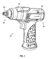
- Fig. 1 is a perspective view of an impact tool according to an embodiment of the invention.
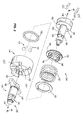
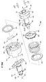
- Fig. 2 is an exploded perspective view of the impact mechanism of Fig. 1 .
- Fig. 3 is another exploded perspective view of the impact mechanism of Fig. 1 .
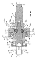
- Fig. 4A is a cross-sectional view of the impact mechanism of Fig. 2 taken along line 4-4.
- Fig. 4B is the cross-sectional view of the impact mechanism of Fig. 4A with the hammer rotated.
- Fig. 5 is a side view of the impact mechanism of Fig. 4 during normal operation.
- Fig. 6 is a side view of the impact mechanism of Fig. 4 when dropped on a rear end.
- Fig. 1 illustrates an impact tool 100 according to an embodiment of the invention.
- the impact tool 100 includes a motor 102, an impact mechanism 104 driven by the motor 102, and an output spindle 105 driven for rotation by the impact mechanism 104.
- the impact tool 100 has a forward or output end 106 and a rear or input end 107.
- the impact tool 100 can be an impact wrench.
- Figs. 2-4B illustrate the impact mechanism 104 according to an embodiment of the invention.
- the impact mechanism 104 is of the type commonly known as a ball-and-cam impact mechanism.
- U.S. Patent 2,160,150 to Jimerson et al . describes a ball-and-cam impact mechanism, the entire disclosure of which is hereby incorporated herein by reference.
- the impact mechanism 104 includes a cam shaft 108, a bearing 110, an impact bearing 112, a hammer 114 and an anvil 116.
- the cam shaft 108 is driven for rotation about a longitudinal axis 118 by the motor 102.
- the cam shaft 108 includes a planetary gear carrier 120 for coupling to the motor 102.
- Gear pin holes 122 extend through the planetary gear carrier 120 and receive pins 125 for coupling to the motor 102.
- the cam shaft 108 is coupled to the hammer 114 through the impact bearing 112.
- the hammer 114 includes an annular recess 123 for receiving the bearing 110.
- the hammer 114 is rotatable over the bearing 110 and in turn drives rotation of the anvil 116 about the longitudinal axis 118.
- the anvil 116 is integrally formed with the output spindle 105.
- the cam shaft 108 and the hammer 114 each include a pair of opposed helical grooves 124 and 126, respectively.
- the hammer grooves 126 have open ends facing the anvil 116 for ease of machining and assembly.
- the cam shaft groove 124 is partially defined by a forward facing wall 124a and a rearward facing wall 124b, while the hammer groove 126 is partially defined by a forward facing wall 126a and lacks a rearward facing wall.
- a pair of balls 130 forming the impact bearing 112 couple the cam shaft 108 to the hammer 114. Each ball 130 is received in a race formed by the hammer groove 126 and the corresponding cam shaft groove 124.
- a spring member 132 and a washer 133 are disposed in between the planetary gear carrier 120 and the hammer 114 to bias the hammer 114 away from the planetary gear carrier 120.
- the washer 133 and an end portion of the spring member 132 are received within the hammer annular recess 123 and abut the bearing 110.
- a spring retainer 134 is located in between the planetary gear carrier 120 and the spring member 132 and includes an annular flange 135 for aligning the spring member 132.
- the spring retainer 134 includes blind holes 136 for receiving the pins 125 extending through the planetary groove carrier 120 and for aligning the spring retainer 134 to the planetary gear carrier 120.
- the cam shaft grooves 124 (see below) in turn are formed in the cam shaft 108 in alignment with the planetary gear carrier 120 so that the spring retainer 134 is aligned to the cam shaft grooves 124.
- a forward-facing end of the hammer 114 includes a pair of lugs or ears 137 for driving rotation of the anvil 116.
- the anvil 116 likewise includes a pair of lugs or ears 138 for cooperating with the hammer lugs 137.
- the spring retainer 134, the spring member 132 and the washer 133 are inserted over the cam shaft 108.
- the bearing 110 is placed within the annular recess 123 and the hammer 114 is inserted over the cam shaft 108 to receive the washer 133 and the end portion of the spring member 132 within the annular recess 123.
- the hammer 114 is moved towards the spring retainer 134 against the force of the spring member 132.
- the spring retainer 134 there is a clearance between the cam shaft 108 and the hammer 114 at the hammer grooves 126 so that the cam shaft groove 124 is exposed.
- This clearance is provided by the open end of the hammer grooves 126, and is slightly greater than a diameter of the balls 130.
- One ball 130 is inserted into each of the cam shaft 108 grooves 124 and the hammer 114 is released.
- the biasing force of the spring member 132 forces the hammer 114 away from the spring retainer 134.
- the forward-facing wall 126a of the hammer groove 126 presses against a rearward portion of the balls 130. This presses a forward portion of the balls 130 against the rearward-facing surface 124b of the cam shaft groove 124.
- the balls 130 are thereby trapped between the cam shaft 108 and the hammer 114, and couple the hammer 114 to the cam shaft 108.
- the cam shaft groove 124 need not be aligned with the hammer groove 126 to permit installation; rather, as the hammer 114 moves away from the cam shaft 108 when released, the hammer 114 rotates slightly over the balls 130 to align the hammer groove 126 with the cam shaft groove 124 in a neutral position.
- the impact mechanism 104 further includes an axial stop for limiting axial displacement of the hammer 114 towards the rear end 107.
- the axial stop includes a first pair of stop members 140 on the spring retainer 134 facing the hammer 114 and a pair of corresponding second stop members 142 on the hammer 114 facing the spring retainer 134.
- the stop members 140, 142 are bosses. In other embodiments (not shown), the stop members 140, 142 may have different shapes, and may be shaped differently from one another.
- the first stop members 140 are aligned with the helical grooves 124 as well as the gear pin holes 122 on the planetary gear carrier 120.
- the second stop members 142 are likewise aligned with the helical grooves 126. As illustrated in Fig. 4A , the first stop members 140 are aligned with the second stop members 142 about the axis 118 when the impact mechanism 104 is not in use (i.e., when in the neutral position).
- the motor 102 drives rotation of the cam shaft 108 about the longitudinal axis 118.
- the hammer 114 rotates with the cam shaft 108 over the bearing 110. Rotational torque is transferred from the cam shaft 108 to the hammer 114 through the impact bearing 112.
- the hammer lugs 137 cooperate with the anvil lugs 138 to drive rotation of the anvil 116 and thereby the output spindle 105.
- Fig. 5 shows the impact mechanism 104 as the nut tightens (nut not shown).
- the hammer 114 begins to rotate more slowly than the cam shaft 108.
- the rotation of the cam shaft 108 relative to the hammer 114 causes the balls 130 to roll along the grooves 124, 126 so that the hammer 114 pulls to the rear end 107 against the force of the spring member 132.
- the hammer 114 thus backs up the helical grooves 124 over the balls 130 away from the anvil 116.
- the balls 130 likewise travel along the grooves 124, 126 and remain trapped between the forward facing wall 126a and the rearward facing wall 124b.
- the hammer lugs 137 are thus lifted over the anvil lugs 138, which permits the hammer 114 to rotate unimpeded relative to the anvil 116 one-half of a revolution.
- the hammer 114 rotates, the hammer 114 travels back down the helical grooves 124 towards the anvil 116 under the force of the spring member 132.
- the hammer 114 is thrust forward in time for engagement with the anvil lugs 138 at impact.
- the hammer 114 moves along a first travel path that includes a helical rotation about the cam shaft 108.
- helical rotation it is meant that the first travel path both rotates about the cam shaft 108 and travels axially along the cam shaft 108.
- the axial stop does not interfere with axial travel of the hammer 114 while on the first travel path. This is because as the hammer 114 rotates relative to the spring retainer 134, the second stop members 142 become non-aligned with or circumferentially displaced from the first stop members 140. This non-alignment allows the hammer 114 to move towards the spring retainer 134 without the second stop members 142 encountering the first stop members 140.
- Fig. 6 illustrates the impact mechanism 104 if the impact tool 100 were dropped or struck on an end and in particular the rear end 107.
- the blow to the cam shaft 108 causes the hammer 114 to move against the force of the spring member 132 toward the spring retainer 134 along a second travel path that includes axial travel, but does not rotate.
- the cam shaft groove 124 is partially exposed and clearance between the rearward facing wall 124b of the cam shaft groove 124 and the forward facing wall 126a of the hammer groove 126 approaches the diameter of the balls 130.
- the axial stop thus inhibits axial travel of the hammer 114 towards the rear end 107 when the hammer 114 is not rotating (i.e when the hammer 114 is in a neutral position aligned with cam shaft 134). This feature prevents the balls 130 from escaping the grooves 124, 126 if the impact tool 100 is dropped or struck on an end.
- the axial stop does not, however, inhibit axial travel when the hammer 114 is rotating (i.e., during normal operating conditions). Furthermore, the axial stop does not inhibit axial travel of the hammer 114 when the hammer is intentionally rotated relative to the cam shaft 108 as during assembly.
- This feature permits the hammer groove 126 to be machined with an open end, thus reducing the complexity of machining and providing for a simpler assembly process, while preventing the balls 130 from escaping the grooves 124, 126 through accident or mis-use of the impact tool.
- first stop members 140 and two second stop members 142 are provided opposite one another. In other embodiments, more or fewer stop members are provided.
- the height of the stop members 140, 142 can be selected to determine the distance of non-rotational axial travel permitted. In the illustrated embodiment, the stop members 140, 142 have the same height. In other embodiments (not shown), the height of the stop members 140 is different from the height of the stop members 142.
- the first stop members 140 are provided on the spring retainer 134, which is separate from the cam shaft 108. In other embodiments (not shown), the spring retainer 134 and the first stop members 140 are provided directly on the cam shaft 108.
- the invention provides, among other things, an axial stop for an impact mechanism for preventing the hammer from de-coupling from the cam shaft.
Landscapes
- Engineering & Computer Science (AREA)
- Mechanical Engineering (AREA)
- Percussive Tools And Related Accessories (AREA)
- Details Of Spanners, Wrenches, And Screw Drivers And Accessories (AREA)
Applications Claiming Priority (1)
| Application Number | Priority Date | Filing Date | Title |
|---|---|---|---|
| US11/836,279 US7673702B2 (en) | 2007-08-09 | 2007-08-09 | Impact wrench |
Publications (3)
| Publication Number | Publication Date |
|---|---|
| EP2025473A2 true EP2025473A2 (fr) | 2009-02-18 |
| EP2025473A3 EP2025473A3 (fr) | 2010-09-01 |
| EP2025473B1 EP2025473B1 (fr) | 2013-10-16 |
Family
ID=40039970
Family Applications (1)
| Application Number | Title | Priority Date | Filing Date |
|---|---|---|---|
| EP08162034.6A Not-in-force EP2025473B1 (fr) | 2007-08-09 | 2008-08-07 | Clé à chocs |
Country Status (3)
| Country | Link |
|---|---|
| US (1) | US7673702B2 (fr) |
| EP (1) | EP2025473B1 (fr) |
| CN (1) | CN101362319B (fr) |
Cited By (2)
| Publication number | Priority date | Publication date | Assignee | Title |
|---|---|---|---|---|
| WO2014125813A1 (fr) * | 2013-02-13 | 2014-08-21 | Hitachi Koki Co., Ltd. | Outil à impact |
| US20250135611A1 (en) * | 2023-11-01 | 2025-05-01 | Milwaukee Electric Tool Corporation | Impacting ratchet tool with multiple operating modes |
Families Citing this family (96)
| Publication number | Priority date | Publication date | Assignee | Title |
|---|---|---|---|---|
| EP1961522B1 (fr) * | 2007-02-23 | 2015-04-08 | Robert Bosch Gmbh | Outil d'alimentation rotatif qui fonctionne en mode d'impact ou en mode de forage |
| JP2009226568A (ja) * | 2008-03-25 | 2009-10-08 | Makita Corp | 打撃工具 |
| US20110139474A1 (en) * | 2008-05-05 | 2011-06-16 | Warren Andrew Seith | Pneumatic impact tool |
| JP4600562B2 (ja) * | 2008-09-30 | 2010-12-15 | パナソニック電工株式会社 | インパクト回転工具 |
| US8020630B2 (en) * | 2009-05-29 | 2011-09-20 | Ingersoll Rand Company | Swinging weight assembly for impact tool |
| US8051746B2 (en) * | 2009-06-30 | 2011-11-08 | Ingersoll Rand Company | Ratchet wrench with collar-actuated reversing mechanism |
| CN102971113B (zh) * | 2010-06-30 | 2015-03-25 | 日立工机株式会社 | 冲击工具 |
| WO2012061176A2 (fr) | 2010-11-04 | 2012-05-10 | Milwaukee Electric Tool Corporation | Outil à chocs avec embrayage réglable |
| US8925646B2 (en) | 2011-02-23 | 2015-01-06 | Ingersoll-Rand Company | Right angle impact tool |
| US9592600B2 (en) | 2011-02-23 | 2017-03-14 | Ingersoll-Rand Company | Angle impact tools |
| US10427277B2 (en) * | 2011-04-05 | 2019-10-01 | Ingersoll-Rand Company | Impact wrench having dynamically tuned drive components and method thereof |
| DE102011085765A1 (de) * | 2011-11-04 | 2013-05-08 | Robert Bosch Gmbh | Handwerkzeugmaschine mit einem über einen Handschalter betätigbaren Antriebsmotor |
| DE102011089910A1 (de) * | 2011-12-27 | 2013-06-27 | Robert Bosch Gmbh | Handwerkzeugvorrichtung |
| DE102011089914A1 (de) * | 2011-12-27 | 2013-06-27 | Robert Bosch Gmbh | Handwerkzeugvorrichtung |
| US10464202B2 (en) * | 2012-03-05 | 2019-11-05 | Ingersoll-Rand Company | Power tools with titanium hammer cases and associated flange interfaces |
| DE102012209446A1 (de) * | 2012-06-05 | 2013-12-05 | Robert Bosch Gmbh | Handwerkzeugmaschinenvorrichtung |
| US9272400B2 (en) * | 2012-12-12 | 2016-03-01 | Ingersoll-Rand Company | Torque-limited impact tool |
| US9550283B2 (en) | 2013-01-24 | 2017-01-24 | Ingersoll-Rand Company | Power tool with spindle lock |
| US9022888B2 (en) | 2013-03-12 | 2015-05-05 | Ingersoll-Rand Company | Angle impact tool |
| DE102013208882A1 (de) | 2013-05-14 | 2014-11-20 | Robert Bosch Gmbh | Handwerkzeugvorrichtung |
| US9505107B2 (en) * | 2013-05-14 | 2016-11-29 | Snap-On Incorporated | Ball deflecting chamfer |
| US9573254B2 (en) | 2013-12-17 | 2017-02-21 | Ingersoll-Rand Company | Impact tools |
| US9737978B2 (en) | 2014-02-14 | 2017-08-22 | Ingersoll-Rand Company | Impact tools with torque-limited swinging weight impact mechanisms |
| JP6293033B2 (ja) * | 2014-10-17 | 2018-03-14 | 本田技研工業株式会社 | 環状バネ及びそれを用いたロボット関節機構 |
| USD775919S1 (en) * | 2015-01-02 | 2017-01-10 | Taizhou Beswell Machinery Co., Ltd. | Air impact wrench |
| USD774862S1 (en) * | 2015-06-05 | 2016-12-27 | Ingersoll-Rand Company | Impact tool |
| USD774863S1 (en) * | 2015-06-17 | 2016-12-27 | Ingersoll-Rand Company | Impact tool |
| USD801774S1 (en) * | 2016-03-01 | 2017-11-07 | Atlas Copco Industrial Technique Ab | Pneumatic pulse tool |
| USD801773S1 (en) * | 2016-03-01 | 2017-11-07 | Atlas Copco Industrial Technique Ab | Pneumatic pulse tool |
| TWD185725S (zh) * | 2017-02-13 | 2017-10-01 | 亞柏士氣動工具股份有限公司; | 氣動工具 |
| JP6832509B2 (ja) * | 2017-03-27 | 2021-02-24 | パナソニックIpマネジメント株式会社 | 回転打撃工具 |
| USD839708S1 (en) * | 2017-03-30 | 2019-02-05 | 7Rdd Limited | Torque wrench |
| USD838155S1 (en) * | 2017-07-06 | 2019-01-15 | Apach Industrial Co., Ltd. | Part of hand and machine tools |
| US20190028003A1 (en) | 2017-07-24 | 2019-01-24 | Ingersoll-Rand Company | Outrunner motor in cordless power tool |
| US11097405B2 (en) | 2017-07-31 | 2021-08-24 | Ingersoll-Rand Industrial U.S., Inc. | Impact tool angular velocity measurement system |
| USD853217S1 (en) * | 2018-01-04 | 2019-07-09 | Dino Paoli S.R.L. | Impact wrench |
| AU2019101751B4 (en) * | 2018-02-19 | 2025-11-27 | Milwaukee Electric Tool Corporation | Impact tool |
| TWI658907B (zh) * | 2018-05-25 | 2019-05-11 | 朝程工業股份有限公司 | Double hammer impact wrench |
| CN215789518U (zh) * | 2018-12-10 | 2022-02-11 | 米沃奇电动工具公司 | 冲击工具 |
| WO2020132587A1 (fr) * | 2018-12-21 | 2020-06-25 | Milwaukee Electric Tool Corporation | Outil à impact à couple élevé |
| USD915853S1 (en) * | 2019-08-02 | 2021-04-13 | Taizhou Beswell Machinery Co., Ltd | Impact driver |
| USD929834S1 (en) * | 2019-08-15 | 2021-09-07 | Vis, Llc | Impact wrench |
| JP7320419B2 (ja) | 2019-09-27 | 2023-08-03 | 株式会社マキタ | 回転打撃工具 |
| JP7386027B2 (ja) * | 2019-09-27 | 2023-11-24 | 株式会社マキタ | 回転打撃工具 |
| US11389933B2 (en) * | 2019-09-30 | 2022-07-19 | Ingersoll-Rand Industrial U.S., Inc. | Anti-topping impact tool mechanism |
| USD929836S1 (en) * | 2019-10-08 | 2021-09-07 | Vis, Llc | Impact wrench |
| USD929835S1 (en) * | 2019-10-08 | 2021-09-07 | Vis, Llc | Impact wrench |
| USD934042S1 (en) * | 2019-10-09 | 2021-10-26 | Würth International Ag | Caulking gun |
| USD934644S1 (en) * | 2019-10-17 | 2021-11-02 | Atlas Copco Industrial Technique Ab | Power tool |
| USD931700S1 (en) | 2019-10-17 | 2021-09-28 | Atlas Copco Industrial Technique Ab | Power tool |
| JP1660033S (fr) * | 2019-11-21 | 2020-05-25 | ||
| JP1656306S (fr) * | 2019-11-21 | 2021-03-29 | ||
| USD935294S1 (en) * | 2019-12-12 | 2021-11-09 | Wei Zhao | Electric wrench |
| CN211918327U (zh) * | 2020-01-08 | 2020-11-13 | 王顺清 | 一种汽车空调吹风调节拨片活动卡扣结构 |
| WO2021173602A1 (fr) | 2020-02-24 | 2021-09-02 | Milwaukee Electric Tool Corporation | Outil à percussion |
| USD948978S1 (en) | 2020-03-17 | 2022-04-19 | Milwaukee Electric Tool Corporation | Rotary impact wrench |
| USD958624S1 (en) * | 2020-05-01 | 2022-07-26 | Snap-On Incorporated | Pneumatic impact wrench |
| USD953831S1 (en) * | 2020-05-15 | 2022-06-07 | Apex Brands, Inc. | Battery powered tool |
| USD951736S1 (en) * | 2020-05-18 | 2022-05-17 | Snap-On Incorporated | Impact wrench |
| USD974870S1 (en) * | 2020-07-20 | 2023-01-10 | Snap-On Incorporated | Impact wrench |
| JP7459747B2 (ja) * | 2020-09-30 | 2024-04-02 | 工機ホールディングス株式会社 | インパクト工具 |
| USD956501S1 (en) * | 2020-11-06 | 2022-07-05 | Black & Decker Inc. | Impact tool |
| USD1069533S1 (en) * | 2021-10-25 | 2025-04-08 | Snap-On Incorporated | Power tool and housing |
| JP7762058B2 (ja) * | 2021-12-17 | 2025-10-29 | 株式会社マキタ | インパクト工具 |
| CN116330205B (zh) * | 2021-12-24 | 2026-03-27 | 南京泉峰科技有限公司 | 冲击工具 |
| JP7876344B2 (ja) * | 2022-06-13 | 2026-06-19 | 株式会社マキタ | インパクト工具 |
| USD1042070S1 (en) * | 2023-05-16 | 2024-09-17 | Taizhou Beswell Machinery Co., Ltd. | Rechargeable driver |
| USD1050841S1 (en) * | 2023-04-04 | 2024-11-12 | Ingersoll-Rand Industrial U.S., Inc. | Impact tool |
| USD1052371S1 (en) | 2023-04-04 | 2024-11-26 | Ingersoll-Rand Industrial U.S., Inc. | Impact tool |
| USD1050842S1 (en) * | 2023-04-25 | 2024-11-12 | Lincoln Global, Inc. | Plasma hand torch |
| SE2330204A1 (en) * | 2023-05-05 | 2024-10-29 | Atlas Copco Ind Technique Ab | Power tool comprising a pulse unit |
| USD1042071S1 (en) * | 2023-05-11 | 2024-09-17 | Zhejiang Yagui Technology Co., Ltd. | Electric wrench |
| USD1042069S1 (en) * | 2023-05-16 | 2024-09-17 | Taizhou Beswell Machinery Co., Ltd. | Impact driver |
| USD1049812S1 (en) * | 2023-05-16 | 2024-11-05 | Taizhou Beswell Machinery Co., Ltd. | Impact driver |
| JP1753772S (ja) * | 2023-05-22 | 2023-09-22 | 携帯用電気インパクトドライバー本体 | |
| USD1007272S1 (en) * | 2023-09-06 | 2023-12-12 | Haili Jin | Impact wrench |
| USD1069534S1 (en) * | 2023-09-27 | 2025-04-08 | Shenzhen Akazhi Technology Co., Ltd. | Impact wrench |
| USD1079429S1 (en) * | 2023-12-28 | 2025-06-17 | Min Zhao | Wrench |
| US20250229402A1 (en) * | 2024-01-12 | 2025-07-17 | Milwaukee Electric Tool Corporation | Camshaft for power tool |
| USD1114578S1 (en) * | 2024-01-19 | 2026-02-24 | Zhaosong Yao | Electric wrench |
| USD1094047S1 (en) * | 2024-01-29 | 2025-09-23 | Jiangsu Dongcheng Tools Technology Co., Ltd | Impact wrench |
| DE102025110587A1 (de) * | 2024-03-19 | 2025-09-25 | Milwaukee Electric Tool Corporation | Elektrowerkzeug mit geschlossenem Getriebegehäuse |
| USD1094049S1 (en) * | 2024-03-27 | 2025-09-23 | Jiangsu Dongcheng Tools Technology Co., Ltd | Impact wrench |
| USD1094053S1 (en) * | 2024-04-03 | 2025-09-23 | Jiangsu Dongcheng Tools Technology Co., Ltd | Impact wrench |
| USD1094048S1 (en) * | 2024-04-16 | 2025-09-23 | Jiangsu Dongcheng Tools Technology Co., Ltd | Impact wrench |
| USD1083541S1 (en) * | 2024-05-17 | 2025-07-15 | XiaoCheng Wang | Electric wrench |
| CA230740S (en) * | 2024-06-01 | 2025-06-20 | New World Tech Inc | Electric torque wrench |
| USD1042072S1 (en) * | 2024-06-01 | 2024-09-17 | Qingdao Kaierte E-Commerce Co., Ltd. | Cordless impact wrench |
| USD1083542S1 (en) * | 2024-06-19 | 2025-07-15 | XiaoCheng Wang | Electric wrench |
| USD1049813S1 (en) * | 2024-08-05 | 2024-11-05 | Yanrong Fu | Impact wrench |
| USD1106786S1 (en) * | 2024-10-28 | 2025-12-23 | New World Technologies Inc. | Part of impact driver |
| USD1120723S1 (en) * | 2024-10-31 | 2026-03-31 | Jiangsu Dongcheng Tools Technology Co., Ltd. | Power screwdriver |
| USD1108912S1 (en) * | 2024-12-05 | 2026-01-13 | Taizhou Beswell Machinery Co., Ltd. | Impact driver with handle |
| USD1108913S1 (en) * | 2024-12-05 | 2026-01-13 | Taizhou Beswell Machinery Co., Ltd. | Impact driver with handles |
| USD1105880S1 (en) * | 2025-01-13 | 2025-12-16 | Yanrong Fu | Impact wrench |
| USD1075455S1 (en) * | 2025-01-18 | 2025-05-20 | Guangzhou Aike Information Technology Co., Ltd. | Impact wrench |
Citations (5)
| Publication number | Priority date | Publication date | Assignee | Title |
|---|---|---|---|---|
| JP2002046079A (ja) | 2000-07-31 | 2002-02-12 | Matsushita Electric Works Ltd | 鋼球脱落を防止したインパクト回転工具 |
| JP2003071736A (ja) | 2001-08-31 | 2003-03-12 | Matsushita Electric Works Ltd | インパクト工具 |
| DE202005017305U1 (de) | 2005-11-05 | 2006-02-16 | TRANMAX MACHINERY Co., Ltd., Taiping | Vorrichtung, die das Herausfallen von Führungskugeln einer Schlagwerkzeugeinheit verhindert |
| JP2006175553A (ja) | 2004-12-22 | 2006-07-06 | Matsushita Electric Works Ltd | インパクト回転工具 |
| DE202006014850U1 (de) | 2006-09-27 | 2006-11-23 | Robert Bosch Gmbh | Mechanisches Schlagwerk |
Family Cites Families (17)
| Publication number | Priority date | Publication date | Assignee | Title |
|---|---|---|---|---|
| US2160150A (en) * | 1937-10-21 | 1939-05-30 | Ingersoll Rand Co | Impact wrench |
| US2712254A (en) * | 1953-05-14 | 1955-07-05 | Schodeberg Carl Theodore | Power driven impact tool |
| US3001428A (en) * | 1960-02-23 | 1961-09-26 | Master Power Corp | Rotary impact wrench |
| US3174597A (en) * | 1961-12-19 | 1965-03-23 | Chicago Pneumatic Tool Co | Impact clutch |
| US3174606A (en) * | 1962-12-20 | 1965-03-23 | Ingersoll Rand Co | Torque control for driving means |
| US3198303A (en) * | 1964-01-06 | 1965-08-03 | Ingersoll Rand Co | Rotary impact tool |
| US3414066A (en) * | 1966-08-31 | 1968-12-03 | Chicago Pneumatic Tool Co | Impact wrench |
| US4277074A (en) * | 1979-11-26 | 1981-07-07 | Harry Kilberis | Keyless chuck |
| US4811797A (en) * | 1987-10-21 | 1989-03-14 | Nauchno-Proizvodstvennoe Obiedinenie Po Mekhanizirovannomu Stroitelnomu Instrumentru I Otdelochnym Mashinam | Impact wrench |
| JP3568128B2 (ja) * | 1994-02-25 | 2004-09-22 | 日立工機株式会社 | 回転打撃工具 |
| DE19717624A1 (de) * | 1996-05-17 | 1997-11-20 | Mitsuba Corp | Reduktionsgetriebe mit einem Stoßabsorbiermechanismus |
| US5836403A (en) * | 1996-10-31 | 1998-11-17 | Snap-On Technologies, Inc. | Reversible high impact mechanism |
| US5992538A (en) * | 1997-08-08 | 1999-11-30 | Power Tool Holders Incorporated | Impact tool driver |
| US6158526A (en) * | 1999-03-09 | 2000-12-12 | Snap-On Tools Company | Reversible impact mechanism with structure limiting hammer travel |
| JP3911905B2 (ja) * | 1999-04-30 | 2007-05-09 | 松下電工株式会社 | インパクト回転工具 |
| US6733414B2 (en) * | 2001-01-12 | 2004-05-11 | Milwaukee Electric Tool Corporation | Gear assembly for a power tool |
| JP2002254336A (ja) * | 2001-03-02 | 2002-09-10 | Hitachi Koki Co Ltd | 電動工具 |
-
2007
- 2007-08-09 US US11/836,279 patent/US7673702B2/en active Active
-
2008
- 2008-08-07 EP EP08162034.6A patent/EP2025473B1/fr not_active Not-in-force
- 2008-08-11 CN CN2008102102593A patent/CN101362319B/zh not_active Expired - Fee Related
Patent Citations (5)
| Publication number | Priority date | Publication date | Assignee | Title |
|---|---|---|---|---|
| JP2002046079A (ja) | 2000-07-31 | 2002-02-12 | Matsushita Electric Works Ltd | 鋼球脱落を防止したインパクト回転工具 |
| JP2003071736A (ja) | 2001-08-31 | 2003-03-12 | Matsushita Electric Works Ltd | インパクト工具 |
| JP2006175553A (ja) | 2004-12-22 | 2006-07-06 | Matsushita Electric Works Ltd | インパクト回転工具 |
| DE202005017305U1 (de) | 2005-11-05 | 2006-02-16 | TRANMAX MACHINERY Co., Ltd., Taiping | Vorrichtung, die das Herausfallen von Führungskugeln einer Schlagwerkzeugeinheit verhindert |
| DE202006014850U1 (de) | 2006-09-27 | 2006-11-23 | Robert Bosch Gmbh | Mechanisches Schlagwerk |
Cited By (2)
| Publication number | Priority date | Publication date | Assignee | Title |
|---|---|---|---|---|
| WO2014125813A1 (fr) * | 2013-02-13 | 2014-08-21 | Hitachi Koki Co., Ltd. | Outil à impact |
| US20250135611A1 (en) * | 2023-11-01 | 2025-05-01 | Milwaukee Electric Tool Corporation | Impacting ratchet tool with multiple operating modes |
Also Published As
| Publication number | Publication date |
|---|---|
| EP2025473B1 (fr) | 2013-10-16 |
| CN101362319B (zh) | 2013-03-13 |
| US20090038816A1 (en) | 2009-02-12 |
| US7673702B2 (en) | 2010-03-09 |
| EP2025473A3 (fr) | 2010-09-01 |
| CN101362319A (zh) | 2009-02-11 |
Similar Documents
| Publication | Publication Date | Title |
|---|---|---|
| EP2025473B1 (fr) | Clé à chocs | |
| US7806636B2 (en) | Dead spindle chucking system with sliding sleeve | |
| US7861797B2 (en) | Hand-held machine tool with slip clutch | |
| AU776708B2 (en) | Adjustable spindle lock | |
| US7658239B2 (en) | Power tool, drive assembly, and method of operating the same | |
| US7753381B2 (en) | Tool chuck with sleeve and clutch mechanism to remove operator variability | |
| US7481608B2 (en) | Rotatable chuck | |
| US7455303B2 (en) | Chuck with internal nut | |
| US20030173097A1 (en) | Hand power tool | |
| US5568849A (en) | Clutch mechanism in power driven screwdriver | |
| US7896356B2 (en) | Drill chuck with two-stage gripping | |
| KR101668589B1 (ko) | 스핀들 잠금부를 구비한 전동 공구 | |
| JPH11285986A (ja) | 手持ち式工作機械、特に穴あけドライバ | |
| JPH06114749A (ja) | 携帯電動工具 | |
| US20080302548A1 (en) | Percussion Hammer and/or Drill Hammer Comprising a Safety Coupling | |
| AU2007200080A1 (en) | Power hand tool | |
| US7188557B2 (en) | Tightening tool | |
| EP4163058B1 (fr) | Outil motorisé à impact | |
| CN1943933B (zh) | 具有滑动套筒的静轴卡盘系统 | |
| US20250296215A1 (en) | Tool bit holder with sleeve keyed to spindle | |
| JPH11873A (ja) | ボルトナット締付け機 | |
| CN111278590B (zh) | 一种与具有可旋转驱动轴的动力驱动器一起使用的夹头 |
Legal Events
| Date | Code | Title | Description |
|---|---|---|---|
| PUAI | Public reference made under article 153(3) epc to a published international application that has entered the european phase |
Free format text: ORIGINAL CODE: 0009012 |
|
| AK | Designated contracting states |
Kind code of ref document: A2 Designated state(s): AT BE BG CH CY CZ DE DK EE ES FI FR GB GR HR HU IE IS IT LI LT LU LV MC MT NL NO PL PT RO SE SI SK TR |
|
| AX | Request for extension of the european patent |
Extension state: AL BA MK RS |
|
| PUAL | Search report despatched |
Free format text: ORIGINAL CODE: 0009013 |
|
| AK | Designated contracting states |
Kind code of ref document: A3 Designated state(s): AT BE BG CH CY CZ DE DK EE ES FI FR GB GR HR HU IE IS IT LI LT LU LV MC MT NL NO PL PT RO SE SI SK TR |
|
| AX | Request for extension of the european patent |
Extension state: AL BA MK RS |
|
| 17P | Request for examination filed |
Effective date: 20110214 |
|
| AKX | Designation fees paid |
Designated state(s): DE FR GB IT SE |
|
| 17Q | First examination report despatched |
Effective date: 20111201 |
|
| GRAP | Despatch of communication of intention to grant a patent |
Free format text: ORIGINAL CODE: EPIDOSNIGR1 |
|
| INTG | Intention to grant announced |
Effective date: 20130507 |
|
| GRAS | Grant fee paid |
Free format text: ORIGINAL CODE: EPIDOSNIGR3 |
|
| GRAA | (expected) grant |
Free format text: ORIGINAL CODE: 0009210 |
|
| AK | Designated contracting states |
Kind code of ref document: B1 Designated state(s): DE FR GB IT SE |
|
| REG | Reference to a national code |
Ref country code: GB Ref legal event code: FG4D |
|
| REG | Reference to a national code |
Ref country code: DE Ref legal event code: R096 Ref document number: 602008028092 Country of ref document: DE Effective date: 20131212 |
|
| PG25 | Lapsed in a contracting state [announced via postgrant information from national office to epo] |
Ref country code: SE Free format text: LAPSE BECAUSE OF FAILURE TO SUBMIT A TRANSLATION OF THE DESCRIPTION OR TO PAY THE FEE WITHIN THE PRESCRIBED TIME-LIMIT Effective date: 20131016 |
|
| REG | Reference to a national code |
Ref country code: DE Ref legal event code: R097 Ref document number: 602008028092 Country of ref document: DE |
|
| PLBE | No opposition filed within time limit |
Free format text: ORIGINAL CODE: 0009261 |
|
| STAA | Information on the status of an ep patent application or granted ep patent |
Free format text: STATUS: NO OPPOSITION FILED WITHIN TIME LIMIT |
|
| 26N | No opposition filed |
Effective date: 20140717 |
|
| REG | Reference to a national code |
Ref country code: DE Ref legal event code: R097 Ref document number: 602008028092 Country of ref document: DE Effective date: 20140717 |
|
| REG | Reference to a national code |
Ref country code: FR Ref legal event code: PLFP Year of fee payment: 8 |
|
| REG | Reference to a national code |
Ref country code: FR Ref legal event code: PLFP Year of fee payment: 9 |
|
| REG | Reference to a national code |
Ref country code: FR Ref legal event code: PLFP Year of fee payment: 10 |
|
| REG | Reference to a national code |
Ref country code: FR Ref legal event code: PLFP Year of fee payment: 11 |
|
| PGFP | Annual fee paid to national office [announced via postgrant information from national office to epo] |
Ref country code: IT Payment date: 20190722 Year of fee payment: 12 Ref country code: DE Payment date: 20190722 Year of fee payment: 12 Ref country code: FR Payment date: 20190722 Year of fee payment: 12 |
|
| PGFP | Annual fee paid to national office [announced via postgrant information from national office to epo] |
Ref country code: GB Payment date: 20190722 Year of fee payment: 12 |
|
| REG | Reference to a national code |
Ref country code: GB Ref legal event code: 732E Free format text: REGISTERED BETWEEN 20200806 AND 20200812 |
|
| REG | Reference to a national code |
Ref country code: DE Ref legal event code: R081 Ref document number: 602008028092 Country of ref document: DE Owner name: INGERSOLL-RAND INDUSTRIAL U.S., INC. (N.D.GES., US Free format text: FORMER OWNER: INGERSOLL RAND CO., MONTVALE, N.J., US |
|
| REG | Reference to a national code |
Ref country code: DE Ref legal event code: R082 Ref document number: 602008028092 Country of ref document: DE Representative=s name: HL KEMPNER PATENTANWALT, RECHTSANWALT, SOLICIT, DE |
|
| REG | Reference to a national code |
Ref country code: DE Ref legal event code: R119 Ref document number: 602008028092 Country of ref document: DE |
|
| GBPC | Gb: european patent ceased through non-payment of renewal fee |
Effective date: 20200807 |
|
| PG25 | Lapsed in a contracting state [announced via postgrant information from national office to epo] |
Ref country code: DE Free format text: LAPSE BECAUSE OF NON-PAYMENT OF DUE FEES Effective date: 20210302 Ref country code: FR Free format text: LAPSE BECAUSE OF NON-PAYMENT OF DUE FEES Effective date: 20200831 Ref country code: IT Free format text: LAPSE BECAUSE OF NON-PAYMENT OF DUE FEES Effective date: 20200807 |
|
| PG25 | Lapsed in a contracting state [announced via postgrant information from national office to epo] |
Ref country code: GB Free format text: LAPSE BECAUSE OF NON-PAYMENT OF DUE FEES Effective date: 20200807 |