EP2025480B1 - Maschine zur Bearbeitung von Tür- und Fensterteilen aus Holz oder dergleichen - Google Patents
Maschine zur Bearbeitung von Tür- und Fensterteilen aus Holz oder dergleichen Download PDFInfo
- Publication number
- EP2025480B1 EP2025480B1 EP08161895A EP08161895A EP2025480B1 EP 2025480 B1 EP2025480 B1 EP 2025480B1 EP 08161895 A EP08161895 A EP 08161895A EP 08161895 A EP08161895 A EP 08161895A EP 2025480 B1 EP2025480 B1 EP 2025480B1
- Authority
- EP
- European Patent Office
- Prior art keywords
- machine
- component part
- bridge crane
- bed
- machining unit
- Prior art date
- Legal status (The legal status is an assumption and is not a legal conclusion. Google has not performed a legal analysis and makes no representation as to the accuracy of the status listed.)
- Active
Links
Images


Classifications
-
- B—PERFORMING OPERATIONS; TRANSPORTING
- B27—WORKING OR PRESERVING WOOD OR SIMILAR MATERIAL; NAILING OR STAPLING MACHINES IN GENERAL
- B27C—PLANING, DRILLING, MILLING, TURNING OR UNIVERSAL MACHINES FOR WOOD OR SIMILAR MATERIAL
- B27C9/00—Multi-purpose machines; Universal machines; Equipment therefor
- B27C9/04—Multi-purpose machines; Universal machines; Equipment therefor with a plurality of working spindles
-
- B—PERFORMING OPERATIONS; TRANSPORTING
- B27—WORKING OR PRESERVING WOOD OR SIMILAR MATERIAL; NAILING OR STAPLING MACHINES IN GENERAL
- B27M—WORKING OF WOOD NOT PROVIDED FOR IN SUBCLASSES B27B - B27L; MANUFACTURE OF SPECIFIC WOODEN ARTICLES
- B27M1/00—Working of wood not provided for in subclasses B27B - B27L, e.g. by stretching
- B27M1/08—Working of wood not provided for in subclasses B27B - B27L, e.g. by stretching by multi-step processes
-
- B—PERFORMING OPERATIONS; TRANSPORTING
- B27—WORKING OR PRESERVING WOOD OR SIMILAR MATERIAL; NAILING OR STAPLING MACHINES IN GENERAL
- B27M—WORKING OF WOOD NOT PROVIDED FOR IN SUBCLASSES B27B - B27L; MANUFACTURE OF SPECIFIC WOODEN ARTICLES
- B27M3/00—Manufacture or reconditioning of specific semi-finished or finished articles
- B27M3/08—Manufacture or reconditioning of specific semi-finished or finished articles of specially shaped wood laths or strips
Definitions
- the present invention relates to a machine for working door and window component parts of wood or similar.
- door and window is intended to mean doors, windows, and furniture doors comprising an annular frame, and a panel, e.g. a pane of glass, fitted inside the frame.
- Door and window component parts are worked on a machine comprising an elongated bed with two longitudinal guide members parallel to a first horizontal direction; a number of cross members fitted between the longitudinal guide members and movable along the longitudinal guide members in the first direction; at least one clamping device fitted to each cross member to clamp at least one component part; a bridge crane movable in the first direction along the bed; and a machining unit movable along the bridge crane in a second horizontal direction crosswise to the first direction.
- the component part is normally elongated and substantially parallelepiped-shaped, is clamped by the clamping device in a direction parallel to the first direction, and is shaped longitudinally to form a cavity bounded vertically by two ribs parallel to the first direction, and one of which is detached from the component part to form a bead by which, in use, to secure said panel to the other rib.
- Document EP-A-1247611 on which the preamble of claim 1 is based, discloses a machine for working workpieces of wood or similar comprising a bed extending in a first direction; at least two cross members extending in a second direction crosswise to the first direction, and movable along the bed in the first direction; at least one clamping device fitted to each cross member to clamp at least one component part parallel to the first direction; a bridge crane movable along the bed in the first direction; and a pair of tool groups for machining the workpieces.
- Document DE-A-19820409 discloses a method of detaching a glass stop from a door or window component and of provisory fixing the glass stop to the workpiece.
- Document EP-A-1477286 discloses a method and a machine for machining door and window frame components, wherein the component is longitudinally profiled and transversally tenoned while moved at all times inside the same pocket.
- Document FR-A-2475453 discloses a method of detaching a glass stop from a door or window component and of provisory fixing the glass stop to the workpiece.
- Document EP-A-922547 discloses a machine for machining door and window frame components comprising a bed extending in a first direction; a bridge fixed to the bed;.and a pair of clamping movable along the bed.
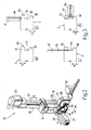
- Number 1 in Figure 1 indicates as a whole a machine for working door and window component parts 2 made of wood or similar, and which are initially elongated and substantially parallelepiped-shaped.
- Machine 1 comprises an elongated, substantially U-shaped bed 3 extending in a horizontal direction 4 and having two lateral longitudinal guide members 5 parallel to direction 4.
- Machine 1 also comprises a bridge crane 6 in turn comprising an upright 7, which is fitted in known manner to bed 3 to move linearly in direction 4 along bed 3, under the control of a known actuating device not shown, and is fitted on its free end with a cross member 8 extending over bed 3 in a horizontal direction 9 crosswise to direction 4, and bounded laterally in direction 4 by two opposite faces 10, 11.
- a bridge crane 6 in turn comprising an upright 7, which is fitted in known manner to bed 3 to move linearly in direction 4 along bed 3, under the control of a known actuating device not shown, and is fitted on its free end with a cross member 8 extending over bed 3 in a horizontal direction 9 crosswise to direction 4, and bounded laterally in direction 4 by two opposite faces 10, 11.
- Bridge crane 6 supports a known machining head 12 fitted to face 10, fitted in known manner to cross member 8 to move linearly along cross member 8 in direction 9, and comprising, in the example shown, at least two electric spindles 13, which have respective longitudinal axes 14 parallel to a vertical direction 15 perpendicular to directions 4 and 9, are fitted in known manner to head 12 to move in direction 15, and are each designed to receive and retain a respective tool or aggregate (not shown).
- Machine 1 also comprises a store M for changing the tools and/or aggregates (not shown) fitted to electric spindles 13, and which is carried by bridge crane 6, and extends along an endless path through upright 7, and is mounted asymmetrically in direction 4 with respect to cross member 8.
- Machine 1 also comprises a number of cross members 16 - hereinafter referred to as "work surfaces" - which extend between longitudinal members 5 in direction 9, and are fitted to longitudinal members 5 to move along longitudinal members 5 in direction 4, either manually or by means of respective known actuating devices not shown.
- Work surfaces 16 support a number of vises 17 which are movable between a grip position and a release position to grip and release at least one component part 2, and the layout of which on work surfaces 16 substantially depends on the size of and the work to be carried out on component parts 2.
- Machine 1 also comprises a feed device 18 for feeding component parts 2, and in turn comprising a bed 19 located alongside bed 3 in direction 4 and supporting a number of belt conveyors 20, which are aligned in direction 4, extend in respective vertical planes parallel to one another and to direction 9, have respective coplanar top conveying branches, and extend in direction 9 between a loading station 21 and an unloading station 22, where the unmachined component parts 2 are loaded and unloaded on and off device 18 respectively.
- a feed device 18 for feeding component parts 2, and in turn comprising a bed 19 located alongside bed 3 in direction 4 and supporting a number of belt conveyors 20, which are aligned in direction 4, extend in respective vertical planes parallel to one another and to direction 9, have respective coplanar top conveying branches, and extend in direction 9 between a loading station 21 and an unloading station 22, where the unmachined component parts 2 are loaded and unloaded on and off device 18 respectively.
- Component parts 2 are transferred between feed device 18 and vises 17 by a grip-and-carry unit 23 comprising an arm 24, which projects in direction 4 from face 11 of cross member 8, is bounded in direction 9 by two opposite faces 25, 26, and is fitted in known manner to cross member 8 to move linearly in direction 9 along cross member 8, under the control of a known actuating device not shown.
- arm 24 supports two grip-and-carry devices 27, 28 defined by respective grippers fitted to face 25; in the example shown, device 27 is fixed to arm 24 in direction 4, and device 28 is fitted in known manner to arm 24 to move linearly in direction 4 along arm 24, under the control of a known actuating device not shown.
- arm 24 also supports a machining unit 29 fitted to face 26 and comprising a supporting plate 30 fitted to arm 24 in fixed manner or movably in direction 4; and a slide 31 which is fitted movably to plate 30, and is connected by a screw-nut screw coupling to a screw 32 rotated by an electric motor 33 to move slide 31 linearly in direction 15.
- Slide 31 supports an electric motor 34 which, with the interposition of a belt drive 35, rotates two shafts 36 connected to slide 31 to rotate about respective longitudinal axes 37 parallel to direction 9, and fitted respectively with a notcher 38 and a blade cutter 39 arranged successively in direction 4.
- component parts 2 are loaded successively onto device 18 - manually or by means of a known loader not shown - at loading station 21, and are fed successively in steps to unloading station 22.
- the component part 2 at station 22 is transferred by grip-and-carry unit 23 to vises 17, is clamped by vises 17 in a direction parallel to direction 4, and is shaped longitudinally by machining head 12 to form a cavity 40 ( Figure 3a ) which is open on the side facing a face 2a of component part 2, is open longitudinally in direction 4, is bounded in direction 15 by two ribs 41, 42 parallel to each other and to direction 4, and is designed to receive and house, in use, a panel (not shown) of the relative door or window (not shown).
- rib 41 is detached from component 2 by notcher 38 and blade cutter 39 to form a bead 43 ( Figures 3b and 3c ) by which, in use, to secure the panel (not shown) of the door or window (not shown) to rib 42, and which is fastened to component part 2 by a number of fasteners 44 inserted between bead 43 and component part 2 by a known inserting device 45 fitted to slide 31, on the opposite side of blade cutter 39 to notcher 38 ( Figure 3d ).
- Figure 4 relates to a machine, which is not part of the invention, and differs from the embodiment shown in the other drawings solely by feed device 18 and grip-and-carry unit 23 being eliminated, and machining unit 29 being mounted directly on face 11 of cross member 8 with the interposition of a slide 46 fitted to cross member 8 to move linearly along cross member 8 in direction 9.
- Machine 1 has several advantages, mainly due to bead 43 remaining connected to the respective original component part 2, and not having to be removed by the operator when detached from component part 2 by notcher 38 and blade cutter 39.
Landscapes
- Life Sciences & Earth Sciences (AREA)
- Engineering & Computer Science (AREA)
- Wood Science & Technology (AREA)
- Forests & Forestry (AREA)
- Mechanical Engineering (AREA)
- Manufacturing & Machinery (AREA)
- Chemical And Physical Treatments For Wood And The Like (AREA)
- Multi-Process Working Machines And Systems (AREA)
- Securing Of Glass Panes Or The Like (AREA)
- Jigs For Machine Tools (AREA)
- Dovetailed Work, And Nailing Machines And Stapling Machines For Wood (AREA)
Claims (10)
- Eine Maschine zur Bearbeitung von Türen- und Fensterteilen (2) aus Holz oder dergleichen, wobei jedes Teil (2) eine anfängliche langgestreckte und im Wesentlichen parallelepipede Form aufweist, die Maschine ein Bett (3), das sich in einer ersten Richtung (4) erstreckt, umfasst; ferner wenigstens zwei Querelemente (16), die sich in einer zweiten Richtung (9) quer zu der ersten Richtung (4) erstrecken und bewegbar entlang des Bettes (3) in der ersten Richtung (4) sind; wenigstens eine Klemmeinrichtung (17), die an jedes Querelement (16) angebaut ist, um wenigstens ein Teil (2) parallel zu der ersten Richtung (4) festzuklemmen; einen Brückenkran (6), der entlang des Bettes (3) in der ersten Richtung (4) bewegbar ist; und wenigstens eine erste Bearbeitungseinheit (12), die entlang des Brückenkranes (6) in der zweiten Richtung (9) bewegbar ist, zur formgebenden Bearbeitung jedes Teils (2) in der Längsrichtung, um eine Ausnehmung (40) zu formen, die auf der Seite offen ist, die einer Seitenfläche (2a) des Teils (2) zugewandt ist, in Längsrichtung in der ersten Richtung (4) offen ist und in einer dritten Richtung (15) senkrecht zu den genannten ersten und zweiten Richtungen (4, 9) durch zwei Rippen (41, 42), die parallel zueinander und zu der ersten Richtung (4) sind, begrenzt ist; und die Maschine ferner dadurch charakterisiert ist, dass sie ferner eine Greif- und Transport-Einheit (23) umfasst, zum Greifen und Transportieren der Teile (2) und welche an den Brückenkran (6) angebaut ist, um sich in der zweiten Richtung (9) zu bewegen und die Teile (2) zu den Klemmeinrichtungen (17) und von diesen weg zu überführen, und ferner dadurch, dass sie eine zweite Bearbeitungseinheit (29) umfasst, ausgestattet mit wenigstens einem Blatt (38, 39) zum Abnehmen einer Rippe (41) von dem Teil (2), wobei die abgenommene Rippe (41) eine Leiste (43) bildet, welche im Gebrauch dazu verwendet wird, eine Glasscheibe der Türe oder des Fensters an der anderen Rippe (42) zu befestigen, und ferner ausgestattet mit einer Einfügeeinrichtung (45), um die Leiste (43) an dem Teil (2) zu befestigen, durch Einfügen wenigstens eines Befestigungselementes (44) zwischen der Leiste (43) und dem Teil (2); wobei die zweite Bearbeitungseinheit (29) an der Greif- und Transport-Einheit (23) angebaut ist, um sich entlang des Brückenkranes (6) in der zweiten Richtung (9) mit demselben Bewegungsgesetz wie die Greif- und Transport-Einheit (23) zu bewegen.
- Eine Maschine, wie in Anspruch 1 beansprucht, wobei die zweite Bearbeitungseinheit (29) in einer dritten Richtung (15) senkrecht zu der genannten ersten und der genannten zweiten Richtung (4, 9) bewegbar ist.
- Ein Maschine, wie in Anspruch 1 oder 2 beansprucht, wobei die erste Bearbeitungseinheit (12) wenigstens eine elektrische Spindel (13) umfasst, an welcher wenigstens ein Werkzeug oder Aggregat zur Bearbeitung des Teils (2) befestigt werden kann; ferner einen Speicher (M), welcher vorgesehen ist, um zu ermöglichen, dass die elektrische Spindel (13) das Werkzeug oder das Aggregat wechselt.
- Eine Maschine, wie sie in Anspruch 3 beansprucht wird, wobei der Brückenkran (6) ein weiteres Querelement (8) umfasst, das sich über das Bett (3) in der zweiten Richtung (9) erstreckt; der Speicher (M) auf dem Brückenkran (6) asymmetrisch in der ersten Richtung (4) mit Bezug auf das weitere Querelement (8) montiert ist.
- Eine Maschine, wie sie in einem der vorhergehenden Ansprüche beansprucht wird, wobei die zweite Bearbeitungseinheit (29) ein erstes Blatt (38) zum Einkerben des Teils (2) aufweist; und ein zweites Blatt (39) zum Abnehmen der Leiste (43) von dem Teil (2).
- Eine Maschine, wie sie in Anspruch 5 beansprucht wird, wobei die zweite Bearbeitungseinheit (29) zwei parallele Tragwellen (36) zum Tragen jeweils des ersten und zweiten Blattes (38, 39) umfasst; und einen elektrischen Motor (34) zum Drehantreiben der Tragwellen (36) über die entsprechenden Längsachsen (37).
- Eine Maschine, wie sie in einem der vorhergehenden Ansprüche beansprucht wird, wobei der Brückenkran (6) ein weiteres Querelement (8) umfasst, das sich über dem Bett (3) in der zweiten Richtung (9) erstreckt und in der ersten Richtung (4) durch zwei einander entgegengesetzte Stirnseiten (10, 11) begrenzt ist; die genannte erste und die genannte zweite Bearbeitungseinheit (12, 29) ist jeweils auf einer ersten und einer zweiten der genannten Stirnseiten (10, 11) montiert.
- Eine Maschine, wie sie in einem der vorhergehenden Ansprüche beansprucht wird, wobei der Brückenkran (6) ein weiteres Querelement (8) umfasst, das sich über das Bett (3) in der zweiten Richtung (9) erstreckt und in der ersten Richtung (4) durch zwei einander entgegengesetzte Stirnseiten (10, 11) begrenzt ist; die erste Bearbeitungseinheit (12) und die Greif- und Transport-Einheit (23) sind jeweils auf einer ersten und einer zweiten der genannten Stirnseiten (10, 11) montiert.
- Eine Maschine, wie sie in Anspruch 8 beansprucht wird, wobei die Greif- und Transport-Einheit (23) einen Tragarm (24) umfasst, der von dem Brückenkran (6) in der ersten Richtung (4) hervorsteht und in der zweiten Richtung (9) durch zwei entgegengesetzt zueinander angeordnete weitere Stirnseiten (25, 26) begrenzt ist; und ferner wenigstens zwei Greif- und Transport-Einrichtungen (27, 28) die zueinander beweglich entlang des Tragarms (24) in der ersten Richtung (4) bewegbar sind; wobei die Greif- und Transport-Einrichtungen (27, 28) und die zweite Bearbeitungseinheit (29) jeweils auf einer ersten und einer zweiten der genannten Stirnseiten (25, 26) montiert sind.
- Eine Maschine, wie sie in Anspruch 9 beansprucht wird, wobei die zweite Bearbeitungseinheit (29) entlang des Tragarms (24) in der ersten Richtung (4) bewegbar ist.
Priority Applications (1)
| Application Number | Priority Date | Filing Date | Title |
|---|---|---|---|
| PL08161895T PL2025480T3 (pl) | 2007-08-06 | 2008-08-06 | Urządzenie do obróbki części składowych drzwi i okien z drewna albo podobnego materiału |
Applications Claiming Priority (1)
| Application Number | Priority Date | Filing Date | Title |
|---|---|---|---|
| IT000566A ITBO20070566A1 (it) | 2007-08-06 | 2007-08-06 | Macchina per la lavorazione di componenti di legno o simili per infissi |
Publications (2)
| Publication Number | Publication Date |
|---|---|
| EP2025480A1 EP2025480A1 (de) | 2009-02-18 |
| EP2025480B1 true EP2025480B1 (de) | 2010-12-22 |
Family
ID=39929621
Family Applications (1)
| Application Number | Title | Priority Date | Filing Date |
|---|---|---|---|
| EP08161895A Active EP2025480B1 (de) | 2007-08-06 | 2008-08-06 | Maschine zur Bearbeitung von Tür- und Fensterteilen aus Holz oder dergleichen |
Country Status (6)
| Country | Link |
|---|---|
| EP (1) | EP2025480B1 (de) |
| AT (1) | ATE492380T1 (de) |
| DE (1) | DE602008004026D1 (de) |
| ES (1) | ES2358163T3 (de) |
| IT (1) | ITBO20070566A1 (de) |
| PL (1) | PL2025480T3 (de) |
Families Citing this family (6)
| Publication number | Priority date | Publication date | Assignee | Title |
|---|---|---|---|---|
| ITMO20100042A1 (it) * | 2010-02-25 | 2011-08-26 | Scm Group Spa | Gruppo operativo per un centro di lavoro |
| GB2492347A (en) | 2011-06-28 | 2013-01-02 | Nicholas Timothy Showan | Building method, cutting apparatus and liquid-laden foam insulator |
| DE102014219070A1 (de) * | 2014-09-22 | 2016-03-24 | Homag Holzbearbeitungssysteme Gmbh | Bearbeitungsvorrichtung |
| DE102014016629A1 (de) * | 2014-11-04 | 2016-05-04 | Michael Weinig Ag | Anlage zur Herstellung und/oder Behandlung von Glasleisten sowie Verfahren unter Verwendung einer solchen Anlage |
| EP3020523B1 (de) * | 2014-11-14 | 2018-09-19 | C.M.S. S.p.A. | Bearbeitungszentrum |
| BE1029395B1 (nl) * | 2021-05-11 | 2022-12-12 | Vertongen Houtbewerkingsmachines | Machine voor het bewerken van een houtenwerkstuk |
Family Cites Families (5)
| Publication number | Priority date | Publication date | Assignee | Title |
|---|---|---|---|---|
| DE3004479C2 (de) * | 1980-02-07 | 1983-09-22 | Hemag Maschinenbau, Ing. A. & F. Manasek Ohg, 6900 Heidelberg | Verfahren bei der Herstellung von Fensterrahmen mit Glashalteleisten aus Holz und Vorrichtung zur Durchführung des Verfahrens |
| DE19752685A1 (de) * | 1997-11-28 | 1999-07-01 | Ima Maschinenfabriken Klessmann Gmbh | Maschine zum Bearbeiten von Fensterrahmen-Holmen |
| DE19820409C2 (de) * | 1998-05-07 | 2000-02-17 | Ingbuero Roob Gmbh | Verfahren zur Herstellung überfälzter Glasleisten |
| US6688352B2 (en) * | 2001-04-06 | 2004-02-10 | Uniteam S.P.A. | Multi-axis work center, for multiple production, in particular for wood working |
| ITBO20030304A1 (it) * | 2003-05-16 | 2004-11-17 | Impresa 2000 Di Sacchi Paride E C S A S | Metodo e macchina per la lavorazione di componenti di infissi |
-
2007
- 2007-08-06 IT IT000566A patent/ITBO20070566A1/it unknown
-
2008
- 2008-08-06 ES ES08161895T patent/ES2358163T3/es active Active
- 2008-08-06 PL PL08161895T patent/PL2025480T3/pl unknown
- 2008-08-06 EP EP08161895A patent/EP2025480B1/de active Active
- 2008-08-06 AT AT08161895T patent/ATE492380T1/de active
- 2008-08-06 DE DE602008004026T patent/DE602008004026D1/de active Active
Also Published As
| Publication number | Publication date |
|---|---|
| ITBO20070566A1 (it) | 2009-02-07 |
| ES2358163T3 (es) | 2011-05-06 |
| ATE492380T1 (de) | 2011-01-15 |
| EP2025480A1 (de) | 2009-02-18 |
| PL2025480T3 (pl) | 2011-05-31 |
| DE602008004026D1 (de) | 2011-02-03 |
Similar Documents
| Publication | Publication Date | Title |
|---|---|---|
| JP4221199B2 (ja) | 木材やプラスチック材料の工作物を加工する機械及び方法 | |
| US10668643B2 (en) | Machining device | |
| EP2025480B1 (de) | Maschine zur Bearbeitung von Tür- und Fensterteilen aus Holz oder dergleichen | |
| CN108025451B (zh) | 一种用于对工件进行加工的加工设备 | |
| CN107838778A (zh) | 一种汽车万向节气动打磨设备 | |
| CN204277454U (zh) | 一体式钻削自动化加工设备 | |
| CN209050393U (zh) | 一种多孔工件的自动加工设备 | |
| CN107813200A (zh) | 一种用于汽车万向节气动打磨设备的打磨装置 | |
| CN218362498U (zh) | 一种圆柱形工件两端倒角机 | |
| US10751906B2 (en) | Wood processing system | |
| CN110385589B (zh) | 一种雕铣机 | |
| CN110961926A (zh) | 法兰加工设备 | |
| CN108015605B (zh) | 一种用于扳手的上料装置 | |
| CN112548780B (zh) | 一种铣刀生产用开槽装置 | |
| EP2275237B1 (de) | Bearbeitungsmachine für Träger, insbesondere für Träger aus Holz oder aus ähnlichem Material | |
| CN210794909U (zh) | 一种上料机构 | |
| CN211388188U (zh) | 铣刀棒料自动平端面倒角磨削生产线 | |
| CN110625196B (zh) | 一种用于转向齿轮套筒的切割装置 | |
| CN221891536U (zh) | 一种刃具端面磨床 | |
| CN220497955U (zh) | 一种全自动双头平面倒角机 | |
| CN112847688A (zh) | 双支木工车铣复合加工中心 | |
| CN209796777U (zh) | 工件翻转输送装置及工件输送系统 | |
| CN215749704U (zh) | 双支木工车铣复合加工中心 | |
| CN205363406U (zh) | 内置有自动上卸料机构数控机床 | |
| EP2022611A1 (de) | Maschine zur Bearbeitung von Bauteilen aus Holz oder dergleichen, insbesondere für Bauteile von Türen oder Fenstern |
Legal Events
| Date | Code | Title | Description |
|---|---|---|---|
| PUAI | Public reference made under article 153(3) epc to a published international application that has entered the european phase |
Free format text: ORIGINAL CODE: 0009012 |
|
| AK | Designated contracting states |
Kind code of ref document: A1 Designated state(s): AT BE BG CH CY CZ DE DK EE ES FI FR GB GR HR HU IE IS IT LI LT LU LV MC MT NL NO PL PT RO SE SI SK TR |
|
| AX | Request for extension of the european patent |
Extension state: AL BA MK RS |
|
| 17P | Request for examination filed |
Effective date: 20090716 |
|
| 17Q | First examination report despatched |
Effective date: 20090812 |
|
| AKX | Designation fees paid |
Designated state(s): AT BE BG CH CY CZ DE DK EE ES FI FR GB GR HR HU IE IS IT LI LT LU LV MC MT NL NO PL PT RO SE SI SK TR |
|
| GRAP | Despatch of communication of intention to grant a patent |
Free format text: ORIGINAL CODE: EPIDOSNIGR1 |
|
| RIC1 | Information provided on ipc code assigned before grant |
Ipc: B27M 3/08 20060101ALI20100506BHEP Ipc: B27M 1/08 20060101ALI20100506BHEP Ipc: B27C 9/04 20060101AFI20100506BHEP |
|
| RIN1 | Information on inventor provided before grant (corrected) |
Inventor name: BERNARDI, PAOLO |
|
| GRAS | Grant fee paid |
Free format text: ORIGINAL CODE: EPIDOSNIGR3 |
|
| GRAA | (expected) grant |
Free format text: ORIGINAL CODE: 0009210 |
|
| AK | Designated contracting states |
Kind code of ref document: B1 Designated state(s): AT BE BG CH CY CZ DE DK EE ES FI FR GB GR HR HU IE IS IT LI LT LU LV MC MT NL NO PL PT RO SE SI SK TR |
|
| REG | Reference to a national code |
Ref country code: GB Ref legal event code: FG4D |
|
| REG | Reference to a national code |
Ref country code: CH Ref legal event code: EP |
|
| REG | Reference to a national code |
Ref country code: IE Ref legal event code: FG4D |
|
| REF | Corresponds to: |
Ref document number: 602008004026 Country of ref document: DE Date of ref document: 20110203 Kind code of ref document: P |
|
| REG | Reference to a national code |
Ref country code: DE Ref legal event code: R096 Ref document number: 602008004026 Country of ref document: DE Effective date: 20110203 |
|
| REG | Reference to a national code |
Ref country code: NL Ref legal event code: VDEP Effective date: 20101222 |
|
| PG25 | Lapsed in a contracting state [announced via postgrant information from national office to epo] |
Ref country code: LT Free format text: LAPSE BECAUSE OF FAILURE TO SUBMIT A TRANSLATION OF THE DESCRIPTION OR TO PAY THE FEE WITHIN THE PRESCRIBED TIME-LIMIT Effective date: 20101222 |
|
| REG | Reference to a national code |
Ref country code: ES Ref legal event code: FG2A Ref document number: 2358163 Country of ref document: ES Kind code of ref document: T3 Effective date: 20110425 |
|
| LTIE | Lt: invalidation of european patent or patent extension |
Effective date: 20101222 |
|
| PG25 | Lapsed in a contracting state [announced via postgrant information from national office to epo] |
Ref country code: HR Free format text: LAPSE BECAUSE OF FAILURE TO SUBMIT A TRANSLATION OF THE DESCRIPTION OR TO PAY THE FEE WITHIN THE PRESCRIBED TIME-LIMIT Effective date: 20101222 Ref country code: SE Free format text: LAPSE BECAUSE OF FAILURE TO SUBMIT A TRANSLATION OF THE DESCRIPTION OR TO PAY THE FEE WITHIN THE PRESCRIBED TIME-LIMIT Effective date: 20101222 Ref country code: CY Free format text: LAPSE BECAUSE OF FAILURE TO SUBMIT A TRANSLATION OF THE DESCRIPTION OR TO PAY THE FEE WITHIN THE PRESCRIBED TIME-LIMIT Effective date: 20101222 Ref country code: SI Free format text: LAPSE BECAUSE OF FAILURE TO SUBMIT A TRANSLATION OF THE DESCRIPTION OR TO PAY THE FEE WITHIN THE PRESCRIBED TIME-LIMIT Effective date: 20101222 Ref country code: LV Free format text: LAPSE BECAUSE OF FAILURE TO SUBMIT A TRANSLATION OF THE DESCRIPTION OR TO PAY THE FEE WITHIN THE PRESCRIBED TIME-LIMIT Effective date: 20101222 Ref country code: FI Free format text: LAPSE BECAUSE OF FAILURE TO SUBMIT A TRANSLATION OF THE DESCRIPTION OR TO PAY THE FEE WITHIN THE PRESCRIBED TIME-LIMIT Effective date: 20101222 Ref country code: BG Free format text: LAPSE BECAUSE OF FAILURE TO SUBMIT A TRANSLATION OF THE DESCRIPTION OR TO PAY THE FEE WITHIN THE PRESCRIBED TIME-LIMIT Effective date: 20110322 |
|
| REG | Reference to a national code |
Ref country code: PL Ref legal event code: T3 |
|
| PG25 | Lapsed in a contracting state [announced via postgrant information from national office to epo] |
Ref country code: PT Free format text: LAPSE BECAUSE OF FAILURE TO SUBMIT A TRANSLATION OF THE DESCRIPTION OR TO PAY THE FEE WITHIN THE PRESCRIBED TIME-LIMIT Effective date: 20110422 Ref country code: NO Free format text: LAPSE BECAUSE OF FAILURE TO SUBMIT A TRANSLATION OF THE DESCRIPTION OR TO PAY THE FEE WITHIN THE PRESCRIBED TIME-LIMIT Effective date: 20110322 Ref country code: EE Free format text: LAPSE BECAUSE OF FAILURE TO SUBMIT A TRANSLATION OF THE DESCRIPTION OR TO PAY THE FEE WITHIN THE PRESCRIBED TIME-LIMIT Effective date: 20101222 Ref country code: BE Free format text: LAPSE BECAUSE OF FAILURE TO SUBMIT A TRANSLATION OF THE DESCRIPTION OR TO PAY THE FEE WITHIN THE PRESCRIBED TIME-LIMIT Effective date: 20101222 Ref country code: IS Free format text: LAPSE BECAUSE OF FAILURE TO SUBMIT A TRANSLATION OF THE DESCRIPTION OR TO PAY THE FEE WITHIN THE PRESCRIBED TIME-LIMIT Effective date: 20110422 Ref country code: CZ Free format text: LAPSE BECAUSE OF FAILURE TO SUBMIT A TRANSLATION OF THE DESCRIPTION OR TO PAY THE FEE WITHIN THE PRESCRIBED TIME-LIMIT Effective date: 20101222 Ref country code: GR Free format text: LAPSE BECAUSE OF FAILURE TO SUBMIT A TRANSLATION OF THE DESCRIPTION OR TO PAY THE FEE WITHIN THE PRESCRIBED TIME-LIMIT Effective date: 20110323 |
|
| PG25 | Lapsed in a contracting state [announced via postgrant information from national office to epo] |
Ref country code: RO Free format text: LAPSE BECAUSE OF FAILURE TO SUBMIT A TRANSLATION OF THE DESCRIPTION OR TO PAY THE FEE WITHIN THE PRESCRIBED TIME-LIMIT Effective date: 20101222 Ref country code: SK Free format text: LAPSE BECAUSE OF FAILURE TO SUBMIT A TRANSLATION OF THE DESCRIPTION OR TO PAY THE FEE WITHIN THE PRESCRIBED TIME-LIMIT Effective date: 20101222 Ref country code: NL Free format text: LAPSE BECAUSE OF FAILURE TO SUBMIT A TRANSLATION OF THE DESCRIPTION OR TO PAY THE FEE WITHIN THE PRESCRIBED TIME-LIMIT Effective date: 20101222 |
|
| PLBE | No opposition filed within time limit |
Free format text: ORIGINAL CODE: 0009261 |
|
| STAA | Information on the status of an ep patent application or granted ep patent |
Free format text: STATUS: NO OPPOSITION FILED WITHIN TIME LIMIT |
|
| PG25 | Lapsed in a contracting state [announced via postgrant information from national office to epo] |
Ref country code: DK Free format text: LAPSE BECAUSE OF FAILURE TO SUBMIT A TRANSLATION OF THE DESCRIPTION OR TO PAY THE FEE WITHIN THE PRESCRIBED TIME-LIMIT Effective date: 20101222 |
|
| 26N | No opposition filed |
Effective date: 20110923 |
|
| PG25 | Lapsed in a contracting state [announced via postgrant information from national office to epo] |
Ref country code: MT Free format text: LAPSE BECAUSE OF FAILURE TO SUBMIT A TRANSLATION OF THE DESCRIPTION OR TO PAY THE FEE WITHIN THE PRESCRIBED TIME-LIMIT Effective date: 20101222 |
|
| REG | Reference to a national code |
Ref country code: DE Ref legal event code: R097 Ref document number: 602008004026 Country of ref document: DE Effective date: 20110923 |
|
| PG25 | Lapsed in a contracting state [announced via postgrant information from national office to epo] |
Ref country code: MC Free format text: LAPSE BECAUSE OF NON-PAYMENT OF DUE FEES Effective date: 20110831 |
|
| REG | Reference to a national code |
Ref country code: FR Ref legal event code: ST Effective date: 20120430 |
|
| REG | Reference to a national code |
Ref country code: IE Ref legal event code: MM4A |
|
| PG25 | Lapsed in a contracting state [announced via postgrant information from national office to epo] |
Ref country code: IE Free format text: LAPSE BECAUSE OF NON-PAYMENT OF DUE FEES Effective date: 20110806 |
|
| PG25 | Lapsed in a contracting state [announced via postgrant information from national office to epo] |
Ref country code: FR Free format text: LAPSE BECAUSE OF NON-PAYMENT OF DUE FEES Effective date: 20110831 |
|
| REG | Reference to a national code |
Ref country code: CH Ref legal event code: PL |
|
| GBPC | Gb: european patent ceased through non-payment of renewal fee |
Effective date: 20120806 |
|
| PG25 | Lapsed in a contracting state [announced via postgrant information from national office to epo] |
Ref country code: CH Free format text: LAPSE BECAUSE OF NON-PAYMENT OF DUE FEES Effective date: 20120831 Ref country code: LI Free format text: LAPSE BECAUSE OF NON-PAYMENT OF DUE FEES Effective date: 20120831 |
|
| PG25 | Lapsed in a contracting state [announced via postgrant information from national office to epo] |
Ref country code: LU Free format text: LAPSE BECAUSE OF NON-PAYMENT OF DUE FEES Effective date: 20110806 |
|
| PG25 | Lapsed in a contracting state [announced via postgrant information from national office to epo] |
Ref country code: GB Free format text: LAPSE BECAUSE OF NON-PAYMENT OF DUE FEES Effective date: 20120806 |
|
| PG25 | Lapsed in a contracting state [announced via postgrant information from national office to epo] |
Ref country code: TR Free format text: LAPSE BECAUSE OF FAILURE TO SUBMIT A TRANSLATION OF THE DESCRIPTION OR TO PAY THE FEE WITHIN THE PRESCRIBED TIME-LIMIT Effective date: 20101222 |
|
| PG25 | Lapsed in a contracting state [announced via postgrant information from national office to epo] |
Ref country code: HU Free format text: LAPSE BECAUSE OF FAILURE TO SUBMIT A TRANSLATION OF THE DESCRIPTION OR TO PAY THE FEE WITHIN THE PRESCRIBED TIME-LIMIT Effective date: 20101222 |
|
| PGFP | Annual fee paid to national office [announced via postgrant information from national office to epo] |
Ref country code: ES Payment date: 20250916 Year of fee payment: 18 |
|
| PGFP | Annual fee paid to national office [announced via postgrant information from national office to epo] |
Ref country code: DE Payment date: 20250827 Year of fee payment: 18 |
|
| PGFP | Annual fee paid to national office [announced via postgrant information from national office to epo] |
Ref country code: PL Payment date: 20250711 Year of fee payment: 18 Ref country code: IT Payment date: 20250707 Year of fee payment: 18 |
|
| PGFP | Annual fee paid to national office [announced via postgrant information from national office to epo] |
Ref country code: AT Payment date: 20250819 Year of fee payment: 18 |