EP2025519A2 - Tintenverteiler für Tintenstrahlaufzeichner - Google Patents
Tintenverteiler für Tintenstrahlaufzeichner Download PDFInfo
- Publication number
- EP2025519A2 EP2025519A2 EP08016500A EP08016500A EP2025519A2 EP 2025519 A2 EP2025519 A2 EP 2025519A2 EP 08016500 A EP08016500 A EP 08016500A EP 08016500 A EP08016500 A EP 08016500A EP 2025519 A2 EP2025519 A2 EP 2025519A2
- Authority
- EP
- European Patent Office
- Prior art keywords
- ink
- reservoir
- recording head
- height
- back pressure
- Prior art date
- Legal status (The legal status is an assumption and is not a legal conclusion. Google has not performed a legal analysis and makes no representation as to the accuracy of the status listed.)
- Granted
Links
- 239000007788 liquid Substances 0.000 claims description 37
- 238000010926 purge Methods 0.000 claims description 17
- 238000001514 detection method Methods 0.000 description 5
- 230000001276 controlling effect Effects 0.000 description 4
- 230000008859 change Effects 0.000 description 3
- 238000004519 manufacturing process Methods 0.000 description 3
- 230000007246 mechanism Effects 0.000 description 3
- 230000004044 response Effects 0.000 description 3
- 238000004891 communication Methods 0.000 description 2
- 230000015572 biosynthetic process Effects 0.000 description 1
- 238000004140 cleaning Methods 0.000 description 1
- 238000007796 conventional method Methods 0.000 description 1
- 238000007599 discharging Methods 0.000 description 1
- 239000000428 dust Substances 0.000 description 1
- 230000001105 regulatory effect Effects 0.000 description 1
- 238000009877 rendering Methods 0.000 description 1
- 230000004043 responsiveness Effects 0.000 description 1
- 239000007787 solid Substances 0.000 description 1
- 238000003860 storage Methods 0.000 description 1
Images
Classifications
-
- B—PERFORMING OPERATIONS; TRANSPORTING
- B41—PRINTING; LINING MACHINES; TYPEWRITERS; STAMPS
- B41J—TYPEWRITERS; SELECTIVE PRINTING MECHANISMS, i.e. MECHANISMS PRINTING OTHERWISE THAN FROM A FORME; CORRECTION OF TYPOGRAPHICAL ERRORS
- B41J2/00—Typewriters or selective printing mechanisms characterised by the printing or marking process for which they are designed
- B41J2/005—Typewriters or selective printing mechanisms characterised by the printing or marking process for which they are designed characterised by bringing liquid or particles selectively into contact with a printing material
- B41J2/01—Ink jet
- B41J2/17—Ink jet characterised by ink handling
- B41J2/175—Ink supply systems ; Circuit parts therefor
-
- B—PERFORMING OPERATIONS; TRANSPORTING
- B41—PRINTING; LINING MACHINES; TYPEWRITERS; STAMPS
- B41J—TYPEWRITERS; SELECTIVE PRINTING MECHANISMS, i.e. MECHANISMS PRINTING OTHERWISE THAN FROM A FORME; CORRECTION OF TYPOGRAPHICAL ERRORS
- B41J2/00—Typewriters or selective printing mechanisms characterised by the printing or marking process for which they are designed
- B41J2/005—Typewriters or selective printing mechanisms characterised by the printing or marking process for which they are designed characterised by bringing liquid or particles selectively into contact with a printing material
- B41J2/01—Ink jet
- B41J2/17—Ink jet characterised by ink handling
- B41J2/175—Ink supply systems ; Circuit parts therefor
- B41J2/17503—Ink cartridges
- B41J2/17506—Refilling of the cartridge
- B41J2/17509—Whilst mounted in the printer
-
- B—PERFORMING OPERATIONS; TRANSPORTING
- B41—PRINTING; LINING MACHINES; TYPEWRITERS; STAMPS
- B41J—TYPEWRITERS; SELECTIVE PRINTING MECHANISMS, i.e. MECHANISMS PRINTING OTHERWISE THAN FROM A FORME; CORRECTION OF TYPOGRAPHICAL ERRORS
- B41J2/00—Typewriters or selective printing mechanisms characterised by the printing or marking process for which they are designed
- B41J2/005—Typewriters or selective printing mechanisms characterised by the printing or marking process for which they are designed characterised by bringing liquid or particles selectively into contact with a printing material
- B41J2/01—Ink jet
- B41J2/17—Ink jet characterised by ink handling
- B41J2/175—Ink supply systems ; Circuit parts therefor
- B41J2/17503—Ink cartridges
- B41J2/17556—Means for regulating the pressure in the cartridge
Definitions
- the present invention relates to a ink supplier for supplying a recording head with ink in an ink jet recorder that is capable of continuous printing operation.
- a subsidiary ink reservoir is used in addition to a main ink reservoir for ink storage and operated to supply ink during the recording and the main ink reservoir is operated to replenish ink when the amount of ink in the subsidiary ink reservoir becomes less than an established value
- an ink supply pump is used to supply ink into the recording head from the subsidiary ink reservoir and the subsidiary ink reservoir is provided with an air vent such that the liquid level of ink in the subsidiary ink reservoir may communicate through it with the atmosphere.
- the reservoir for ink supply to the recording head is provided with the air vent where air in the environment communicates with the ink surface in the reservoir, via which air is entrained into ink in the reservoir.
- Such entrained air may, when fed to the recording head while being carried in ink, hinder the ink from being discharged out of the recording head in the form of properly regulated, successive droplets.
- the pressure of ink supply to the recording head be made optimum individually for each of its operating states, namely during purging, initial charging, printing, wiping of the recording head and cleaning of a wiping blade.
- ink jet recorders for industrial purposes, however, in which their continuous operation is essential, the ink reservoirs must be large in capacity, requiring that they be proportionally large in size and volume, too. Consequently, the drive source and structure need to raise and lower such a main ink reservoir cannot but be large-scaled with conventional techniques, presenting problems in terms of space of placement and manufacturing cost.
- the liquid level becomes controllable less reactively to the ink reservoir raised or lowered. Further, controlling the position head of the ink liquid level by way of software upon measuring the ink supply pressure makes the controller complicate and thus poses the cost problem.
- EP 0 950 533 A2 discloses an ink supplier for an ink jet recorder according to the preamble of claim 1.
- An adjusting device regulates the ink level depending upon the position of the print head so that a predetermined back pressure is maintained at the print head in a first print position having a first elevation and in a second print position having a second elevation which is different to the first elevation.
- the ink surface is, however, not isolated from air in the reservoir, which bears the risk of air entry into the ink and the occurrence of sorts of trouble, such as formation of successive ink droplets upon discharging of ink out of a nozzle and instable printing.
- the mechanism used for the adjustment of the position of the head for ink supply is not light and does not permit manufacturing at reduced costs.
- an ink supplier for an ink jet recorder including a recording head and a main ink reservoir, characterized in that it comprises: a back pressure reservoir connected between the recording head and the main ink reservoir for replenishment with ink from the main ink reservoir, the back pressure reservoir being adapted to maintain a height of the ink liquid level substantially constant against an amount of ink consumption by the recording head; and a means for adjusting the back pressure reservoir in its vertical position, thereby adjusting a position head of the ink liquid level in the back pressure reservoir relative to a printing head face of the recording head.
- the back pressure reservoir designed to be moved vertically to adjust the position head of the ink liquid level therein relative to the recording head can be made compact and light-weighted compared with the main ink reservoir, thereby permitting the position head adjusting mechanism designed to move the back pressure reservoir vertically to adjust the position head. to be made light equipped and manufactured at reduced cost.
- the back pressure reservoir for varying position heads which is made compact and reduced in capacity betters the responsiveness in level control by its vertical movement while improving its maintainability. Further, adjusting the position head of the ink liquid level by moving the back pressure reservoir vertically makes the controller simpler than by controlling the position head of the ink liquid level by way of software upon measuring the ink supply pressure, and thus renders the controller less costly.
- the main ink reservoir will be located in a space like at the motive power side and the back pressure reservoir smaller in size than the main ink reservoir will be placed beside the recoding head; hence the makeup at the recoding head side can also be made compact.
- the back pressure reservoir kept replenished with ink against ink consumption by the recording head, the ink jet printer is allowed to operate continuously over an extended period of time.
- the supply ink pressure can be precisely controlled individually when the recording head is to be placed in each of different modes of such as ink loading, purging, printing and wiping.
- the means may specifically include a lifting unit for supporting the back pressure reservoir so that it can be moved vertically whereby the position head of the ink liquid level in the back pressure reservoir relative to the printing head face of the recording head may have a height H 1 for a printing operation which is lower than the printing head face of the recording head, a height H 2 for a wiping operation which is higher than the printing head face of the recording head, a height H 3 for a purging operation which is higher than that for the wiping operation and a height H 4 for an initial charging operation which is higher than that for the purging operation.
- the height H 1 for an printing operation is about - 20 mm
- the height H 2 for a wiping operation ranges from 10 to 20 mm
- the height H 3 for a purging operation ranges from 35 to 45 mm
- the height H 4 for an initial charging operation is about 45 mm.
- the height H 1 for an printing operation is about - 30 mm
- the height H 2 for a wiping operation ranges from 10 to 20 mm
- the height H 3 for a purging operation ranges from 40 to 100 mm
- the height H 4 for an initial charging operation is about 300 mm.
- an ink supplier capable of maintaining ink supply pressure to a recording head constant while supplying the recording head with ink with an minimum of air entrained therein.
- an ink supplier for an ink jet recorder including a recoding head, a main ink reservoir and a subsidiary ink reservoir connected to the main ink reservoir for replenishment with ink from the main ink reservoir, wherein a means is provided whereby a position head of the ink liquid level in the subsidiary reservoir is maintained substantially constant relative to a printing head face of the recording head.
- the ink supplier constructed as mentioned above wherein the position head of the ink liquid level in the subsidiary ink reservoir is maintained substantially constant relative to the printing head face of the recording head allows ink supply pressure (back pressure) to the recording head to be maintained substantially constant, thereby permitting an printing operation by the recording head to proceed stably.
- the means may include an ink supply conduit connected between the main and subsidiary ink reservoirs, an ink supply pump in the ink supply conduit for supplying ink from the main ink reservoir to the subsidiary ink reservoir, a level detector associated with the subsidiary ink reservoir for detecting an ink liquid level therein and a controller responsive to a detection value of the level detector for controlling ink replenishment by the ink supply pump so as to maintain the position head of the ink liquid level in the subsidiary ink reservoir substantially constant.
- the means for maintaining substantially constant the position head of the ink liquid level in the subsidiary ink reservoir relative to the printing head face of the recording head can be implementation in a simple makeup.
- a deaerator associated with the subsidiary ink reservoir for removing air from ink therein and a float floating on ink in the subsidiary ink reservoir so as to cover the ink substantially over its entire surface.
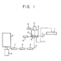
- Fig. 1 is an explanatory view diagrammatically illustrating an ink supply system in an ink supplier according to an aspect which is not part of the present invention but serves for a better understanding thereof.
- An ink jet recorder shown in Fig. 1 includes a recording head 1, a subsidiary ink reservoir 2 connected via an ink supply conduit 3 to the recording head 1 and a main ink reservoir 4 connected via an ink supply conduit 5 to the subsidiary ink reservoir 2.
- the ink supply conduit 5 interconnecting the main ink reservoir 4 and the subsidiary ink reservoir 2 is provided with an ink supply pump 7, a filter 8 and an electromagnetic valve 9.
- the ink supply pump 7 here is provided to replenish the subsidiary ink reservoir 2 with ink from the main ink reservoir 4 against an amount of consumption of ink 6 in the subsidiary ink reservoir 2.
- the ink supply conduits 3 and 5 lie each at a position lower than such as the bottom of the subsidiary ink reservoir 2, namely lower than at least an ink liquid level therein.
- a float 10 is floated on ink 6 stored therein and has enough area to contact the whole surface of the ink.
- the subsidiary ink reservoir 2 also has a level detector 11 for detecting the height of the liquid level of ink 6 by detecting the position of the float 10 therein. And, the operations of the ink supply pump 7 and the electromagnetic valve 9 are controlled by the controller (not shown) in response to a detection value of the level detector 11.
- ink 6 in the subsidiary ink reservoir 2 is being supplied via the ink supply conduit 3 into the recording head 1, when its level in the subsidiary ink reservoir 2 drops below an established level, this is detected by the level detector 11 which then issues a signal to open the electromagnetic valve 9 and also to actuate the ink supply pump 7, whereby ink is supplied from the main ink reservoir 4 into the subsidiary ink reservoir 2.
- the level detector 11 which then issues a signal to deactuate the ink supply pump 7 while closing the electromagnetic valve 9 so that ink supply to the subsidiary ink reservoir 2 is terminated. In this way, the liquid level of ink 6 in the subsidiary ink reservoir 2 is maintained always constant at a selected height.
- the relative position in height between the liquid level of ink 6 in the subsidiary ink reservoir 2 and a head face of the recording head 1 is maintained constant, whereby the liquid level of ink 6 there has its position head H that is maintained substantially constant relative to the printing head face of the recording head 1.
- the subsidiary ink reservoir 2 lies in communication with the atmosphere via a filter 12.
- a deaerator 13 for extracting air from ink 6 therein.
- the main ink reservoir 4 has a deaerator 14 connected thereto for extracting air from ink therein.
- Both the deaerators 13 and 14 may each be of circulatory type whereby air is removed from ink in each reservoir by passing ink in the reservoir through each deaerator 13, 14.
- printing is effected by the recording head 1 operated under control of the controller (not shown) on a sheet of paper (recordable paper) traveling at a position spaced apart by a distance of 0.5 to 1.5 mm below the lower surface of the recording head 1.
- the recording head 1 is supplied with ink from the subsidiary ink reservoir 2 via the ink supply conduit 3 in an amount corresponding to that in which ink is discharged from the recording head 1.
- Ink supply into the recording head 1 here is brought about by capillary actions in the ink supply system and also under a discharge force at the ink discharge nozzle section of the recoding head 1.
- the level in height of ink 6 in the subsidiary ink reservoir 2 is maintained constant by the ink supply pump 7 whose operation is controlled in accordance with a detection value of the level detector 11, and the position head H of the liquid level of ink in the subsidiary ink reservoir 2 is thereby maintained constant relative to the printing head face of the recording head 1, the ink supply pressure at the discharge nozzle section of the recording head 1 is maintained substantially constant.
- the subsidiary and main ink reservoirs 2 and 4 are also deaerated by the deaerators 13 and 14 connected thereto, respectively.
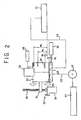
- Fig. 2 is an explanatory view diagrammatically illustrating an ink supply system in an ink supplier according to the present invention.
- An ink jet recorder shown in Fig. 2 includes a recording head 21, a back pressure reservoir (subsidiary ink reservoir) 22 connected via an ink supply conduit 23 to the recording head 21 and a main ink reservoir 24 connected via an ink supply conduit 25 to the back pressure reservoir 22.
- the ink supply conduit 25 interconnecting the main ink reservoir 24 and the back pressure reservoir 22 is provided with an ink supply pump 27, which is provided to replenish the back pressure reservoir 22 with ink from the main ink reservoir 24 as ink 26 in the back pressure reservoir 22 is consumed.
- the ink supply conduits 23 and 25 lie each at a position lower than at least an ink liquid level therein, namely a position such as the bottom of the back pressure reservoir 22.
- the back pressure reservoir 22 is in communication with the atmosphere via a filter 28.
- a float 29 is floated on ink 26 stored therein and has enough area to contact the whole surface of the ink.
- the back pressure reservoir 22 also has a level detector 30 for detecting the height of the liquid level of ink 26 by detecting the position of the float 29 therein. And, the operation of the ink supply pump 27 is controlled by the controller (not shown) in response to a detection value of the level detector 30.
- ink 26 in the back pressure reservoir 22 is being supplied via the ink supply conduit 23 into the recording head 21, when its level in the back pressure reservoir 22 drops below an established level, this is detected by the level detector 30 which then issues a signal to actuate the ink supply pump 27, whereby ink is supplied from the main ink reservoir 24 into the back pressure reservoir 22.
- the level detector 30 which then issues a signal to deactuate the ink supply pump 27 so that ink supply to the back pressure reservoir 22 is terminated. In this way, the liquid level of ink 26 in the back pressure reservoir 22 is maintained always constant at a selected height.
- the back pressure reservoir 22 is supported by a lifting unit 32 with the intermediary of a bracket 31.
- the lifting unit 32 comprises a vertical threaded shaft 33 screwed in the bracket 31 and a motor 34 that can be rotated in both directions to rotate the threaded shaft 33 in either direction vertically and thereby to raise or lower the back pressure reservoir 22.
- rendering the back pressure reservoir 22 movable vertically allows the position head of the liquid level of ink therein to be varied as desired with respect to the printing head face of the recording head 21.
- a deaerator 35 for extracting air from ink 26 therein.
- the deaerator 35 may be of circulatory type whereby air is removed from ink in the reservoir by passing ink in the reservoir through the deaerator 35.
- printing is effected by the recording head 21 operated under control of the controller (not shown) on a sheet of paper (recordable paper) traveling at a position spaced apart by a distance of 0.5 to 1.5 mm below the lower surface of the recording head 21.
- the amount of ink in the back pressure reservoir 22 is maintained constant by the ink supply pump 27 whose operation is controlled in response to a detection value of the level detector 30.
- the height of the ink liquid level, namely its position head, relative to the printing head face of the recording head 21 can be varied by moving the back pressure reservoir 22 vertically by means of the lifting unit 32.
- the position head of the liquid level of ink relative to the printing head face of the recording head 1 is set at different values H 1 , H 2 , H 3 and H 4 selectively for different modes in which the ink jet printer is to be placed, i. e., for printing, wiping, purging and initial charging, respectively.
- the position head H 1 for the printing mode is set to be lower than the printing head face of the recording head 21
- the position head H 2 for the wiping mode is set to be higher than the printing head face of the recording head
- the position head H 3 for the purging mode is set to be higher than H 2 for the wiping mode
- the position head H 4 for the initial charging is set to be higher than H 3 for the purging mode.
- the position head (height) H 1 for the initial charging which needs to draw air out of the ink supply conduit 23 between the back pressure reservoir 22 and the recording head 21 and then to fill the ink supply conduit 23 with ink should be the highest.
- the position head (height) H 3 for the purging operation which to resume printing with a short rest time period after printing is performed to purge or expel dust, solid ink and entrained air and replace them with fresh ink in the ink supply conduit 23 should also be a height near the position head (height) H 4 for the initial charging.
- ink should properly have a negative pressure to the recording head 21 and the position head H 1 (height) should then be a height lower than the printing head face of the recording head 21.
- the position head (height) H 2 during the wiping operation should be some what positive.
- An example is taken as H 1 for printing: about - 20 mm, H 2 for wiping: 10 to 20 mm, H 3 for purging: 35 to 45 mm and H 4 for initial charging: about 45 mm.
- Another example is taken as H 1 for printing: about - 30 mm.
- the back pressure reservoir 22 may have a capacity sufficient if it is commensurate with the printing speed in the recording head. Since it may be smaller in capacity than the main ink reservoir 24, the back pressure reservoir 22 is made smaller than the main ink reservoir 24 in size and weight as well.
Landscapes
- Ink Jet (AREA)
Applications Claiming Priority (3)
| Application Number | Priority Date | Filing Date | Title |
|---|---|---|---|
| JP2004138730A JP2005319655A (ja) | 2004-05-07 | 2004-05-07 | インクジェット記録装置におけるインク供給装置 |
| JP2004139638A JP4685370B2 (ja) | 2004-05-10 | 2004-05-10 | インクジェット記録装置におけるインク供給装置 |
| EP05103284A EP1593519B1 (de) | 2004-05-07 | 2005-04-22 | Tintenzuführvorrichtung für ein Tintenstrahlaufzeichnungsgerät |
Related Parent Applications (2)
| Application Number | Title | Priority Date | Filing Date |
|---|---|---|---|
| EP05103284A Division EP1593519B1 (de) | 2004-05-07 | 2005-04-22 | Tintenzuführvorrichtung für ein Tintenstrahlaufzeichnungsgerät |
| EP05103284.5 Division | 2005-04-22 |
Publications (3)
| Publication Number | Publication Date |
|---|---|
| EP2025519A2 true EP2025519A2 (de) | 2009-02-18 |
| EP2025519A3 EP2025519A3 (de) | 2009-08-12 |
| EP2025519B1 EP2025519B1 (de) | 2010-11-17 |
Family
ID=34939458
Family Applications (2)
| Application Number | Title | Priority Date | Filing Date |
|---|---|---|---|
| EP05103284A Ceased EP1593519B1 (de) | 2004-05-07 | 2005-04-22 | Tintenzuführvorrichtung für ein Tintenstrahlaufzeichnungsgerät |
| EP08016500A Ceased EP2025519B1 (de) | 2004-05-07 | 2005-04-22 | Tintenverteiler für Tintenstrahlaufzeichner |
Family Applications Before (1)
| Application Number | Title | Priority Date | Filing Date |
|---|---|---|---|
| EP05103284A Ceased EP1593519B1 (de) | 2004-05-07 | 2005-04-22 | Tintenzuführvorrichtung für ein Tintenstrahlaufzeichnungsgerät |
Country Status (3)
| Country | Link |
|---|---|
| US (1) | US7628476B2 (de) |
| EP (2) | EP1593519B1 (de) |
| DE (2) | DE602005014907D1 (de) |
Families Citing this family (7)
| Publication number | Priority date | Publication date | Assignee | Title |
|---|---|---|---|---|
| ES2307428B1 (es) * | 2007-05-09 | 2009-10-02 | Jseus Francisco Barberan Latorre | Sistema de alimentacion de tinta para impresoras. |
| JP5430876B2 (ja) * | 2008-05-09 | 2014-03-05 | 理想科学工業株式会社 | インクジェットヘッドのメンテナンス方法 |
| US8167414B1 (en) * | 2008-06-18 | 2012-05-01 | Plastipak Packaging, Inc. | Printing apparatus, system and method |
| KR101943298B1 (ko) * | 2017-04-26 | 2019-01-29 | 주식회사 에스에프에이 | 오토레벨링 잉크젯장치 및 그를 이용한 인쇄 방법 |
| JP7005989B2 (ja) | 2017-07-28 | 2022-01-24 | 京セラドキュメントソリューションズ株式会社 | 供給液タンクユニットおよびそれを備えたインクジェット記録装置 |
| JP7676867B2 (ja) | 2021-03-24 | 2025-05-15 | 京セラドキュメントソリューションズ株式会社 | インクジェット記録装置 |
| WO2025186601A1 (en) * | 2024-03-08 | 2025-09-12 | Gamiy Oleg | Ink supply system for flexographic printing machine |
Citations (2)
| Publication number | Priority date | Publication date | Assignee | Title |
|---|---|---|---|---|
| JPH06106731A (ja) | 1992-09-25 | 1994-04-19 | Canon Inc | インクジェット記録手段およびインクジェット記録装置 |
| EP0950533A2 (de) | 1998-04-13 | 1999-10-20 | Pitney Bowes Inc. | Postmaschine mit einem Tintenstrahldrucker mit Gegendruckregelung |
Family Cites Families (15)
| Publication number | Priority date | Publication date | Assignee | Title |
|---|---|---|---|---|
| US4183030A (en) * | 1976-04-01 | 1980-01-08 | Minolta Camera Kabushiki Kaisha | Ink jet recording apparatus |
| US4342042A (en) * | 1980-12-19 | 1982-07-27 | Pitney Bowes Inc. | Ink supply system for an array of ink jet heads |
| US4502055A (en) * | 1982-05-04 | 1985-02-26 | Ricoh Company, Ltd. | Ink jet deaeration apparatus |
| JPS5941273A (ja) * | 1982-09-01 | 1984-03-07 | Ricoh Co Ltd | 偏向制御インクジエツト記録装置 |
| JPS58212956A (ja) * | 1983-04-23 | 1983-12-10 | Minolta Camera Co Ltd | インクジエツト式記録装置 |
| EP0237787A3 (de) * | 1986-03-20 | 1988-01-13 | Hewlett-Packard Company | Verfahren und Gerät zur Aufrechterhaltung eines im wesentlichen konstanten Tintendruckes in einem getrennt geführten Tintendruckkopf |
| US5920332A (en) * | 1993-05-04 | 1999-07-06 | Markem Corporation | Ink barrier for fluid reservoir vacuum or pressure line |
| JPH07137286A (ja) | 1993-06-29 | 1995-05-30 | Ricoh Co Ltd | インクジェットプリンタ |
| JPH10323994A (ja) * | 1997-04-14 | 1998-12-08 | Xerox Corp | インクジェットプリンタにおけるインク圧力保持システム |
| JPH10286974A (ja) * | 1997-04-14 | 1998-10-27 | Brother Ind Ltd | インクジェットプリンタ |
| JPH1120180A (ja) | 1997-07-02 | 1999-01-26 | Citizen Watch Co Ltd | インクタンクの圧力調整機構 |
| US6054901A (en) * | 1997-10-02 | 2000-04-25 | Motorola, Inc. | Low noise preamplifier |
| JP3704942B2 (ja) * | 1998-03-31 | 2005-10-12 | ブラザー工業株式会社 | インクジェット記録装置 |
| JP2001232816A (ja) * | 2000-02-25 | 2001-08-28 | Hitachi Koki Co Ltd | インクジェット記録装置及びインク供給方法 |
| EP1244558B1 (de) * | 2000-10-23 | 2013-02-27 | Hewlett-Packard Industrial Printing Ltd. | Geschlossenes tintenzuführsystem mit druckkopf-tintendruckregelung und zugehöriges verfahren |
-
2005
- 2005-04-22 EP EP05103284A patent/EP1593519B1/de not_active Ceased
- 2005-04-22 DE DE602005014907T patent/DE602005014907D1/de not_active Expired - Lifetime
- 2005-04-22 EP EP08016500A patent/EP2025519B1/de not_active Ceased
- 2005-04-22 DE DE602005024876T patent/DE602005024876D1/de not_active Expired - Lifetime
- 2005-04-27 US US11/115,795 patent/US7628476B2/en not_active Expired - Lifetime
Patent Citations (2)
| Publication number | Priority date | Publication date | Assignee | Title |
|---|---|---|---|---|
| JPH06106731A (ja) | 1992-09-25 | 1994-04-19 | Canon Inc | インクジェット記録手段およびインクジェット記録装置 |
| EP0950533A2 (de) | 1998-04-13 | 1999-10-20 | Pitney Bowes Inc. | Postmaschine mit einem Tintenstrahldrucker mit Gegendruckregelung |
Also Published As
| Publication number | Publication date |
|---|---|
| DE602005014907D1 (de) | 2009-07-30 |
| EP1593519A3 (de) | 2007-07-11 |
| EP2025519B1 (de) | 2010-11-17 |
| DE602005024876D1 (de) | 2010-12-30 |
| US7628476B2 (en) | 2009-12-08 |
| EP1593519A2 (de) | 2005-11-09 |
| US20050248607A1 (en) | 2005-11-10 |
| EP2025519A3 (de) | 2009-08-12 |
| EP1593519B1 (de) | 2009-06-17 |
Similar Documents
| Publication | Publication Date | Title |
|---|---|---|
| EP0872346B1 (de) | Tintenstrahldrucker | |
| US7874656B2 (en) | Ink-feeding device and pressure-generating method | |
| US4462037A (en) | Ink level control for ink jet printer | |
| US20160368273A1 (en) | Liquid droplet ejecting apparatus that reduces fluctuation of liquid pressure during liquid ejection | |
| EP1892101A1 (de) | Tintenzufuhrvorrichtung in tintenstrahlaufzeichnungsvorrichtung | |
| US8833897B2 (en) | Inkjet device and controlling method for inkjet device | |
| US11491793B2 (en) | Liquid ejecting apparatus and maintenance method for liquid ejecting apparatus | |
| JP2004291618A (ja) | インクジェットヘッドクリーニング装置およびインクジェット記録装置 | |
| US7344231B2 (en) | Inkjet digital printing device and ink reservoir | |
| US20090262151A1 (en) | Inkjet printer system and ink supply apparatus | |
| JP2010504230A (ja) | インク供給システム | |
| EP2025519B1 (de) | Tintenverteiler für Tintenstrahlaufzeichner | |
| JP2005319655A (ja) | インクジェット記録装置におけるインク供給装置 | |
| JP2019084772A (ja) | インク循環システム、インクジェットプリンタ、およびインク循環システムのパラメータ設定方法 | |
| CN113829757A (zh) | 一种工业打印机的墨水系统 | |
| EP1726440B1 (de) | Tintenversorgungsvorrichtung | |
| JP2008105360A (ja) | インク貯留容器およびインクジェット記録装置 | |
| JP2010099855A (ja) | インクジェット記録装置 | |
| JP2001270133A (ja) | インクジェット記録装置 | |
| JP2011000823A (ja) | インク供給装置、インク供給方法、及びインクジェット記録装置 | |
| JP2010173241A (ja) | インクジェットプリンタ | |
| JP2022040650A (ja) | インクジェットプリンタ | |
| JP4685370B2 (ja) | インクジェット記録装置におけるインク供給装置 | |
| JP2003127421A (ja) | インク補給方法 | |
| US20220242136A1 (en) | Liquid circulation mechanism, liquid circulation device, and liquid discharging apparatus |
Legal Events
| Date | Code | Title | Description |
|---|---|---|---|
| PUAI | Public reference made under article 153(3) epc to a published international application that has entered the european phase |
Free format text: ORIGINAL CODE: 0009012 |
|
| AC | Divisional application: reference to earlier application |
Ref document number: 1593519 Country of ref document: EP Kind code of ref document: P |
|
| AK | Designated contracting states |
Kind code of ref document: A2 Designated state(s): DE FR GB |
|
| PUAL | Search report despatched |
Free format text: ORIGINAL CODE: 0009013 |
|
| AK | Designated contracting states |
Kind code of ref document: A3 Designated state(s): DE FR GB |
|
| AKX | Designation fees paid | ||
| 17P | Request for examination filed |
Effective date: 20091021 |
|
| RBV | Designated contracting states (corrected) |
Designated state(s): DE FR GB |
|
| GRAP | Despatch of communication of intention to grant a patent |
Free format text: ORIGINAL CODE: EPIDOSNIGR1 |
|
| GRAS | Grant fee paid |
Free format text: ORIGINAL CODE: EPIDOSNIGR3 |
|
| GRAA | (expected) grant |
Free format text: ORIGINAL CODE: 0009210 |
|
| AC | Divisional application: reference to earlier application |
Ref document number: 1593519 Country of ref document: EP Kind code of ref document: P |
|
| AK | Designated contracting states |
Kind code of ref document: B1 Designated state(s): DE FR GB |
|
| REG | Reference to a national code |
Ref country code: GB Ref legal event code: FG4D |
|
| REF | Corresponds to: |
Ref document number: 602005024876 Country of ref document: DE Date of ref document: 20101230 Kind code of ref document: P |
|
| PLBE | No opposition filed within time limit |
Free format text: ORIGINAL CODE: 0009261 |
|
| STAA | Information on the status of an ep patent application or granted ep patent |
Free format text: STATUS: NO OPPOSITION FILED WITHIN TIME LIMIT |
|
| 26N | No opposition filed |
Effective date: 20110818 |
|
| REG | Reference to a national code |
Ref country code: DE Ref legal event code: R097 Ref document number: 602005024876 Country of ref document: DE Effective date: 20110818 |
|
| REG | Reference to a national code |
Ref country code: FR Ref legal event code: PLFP Year of fee payment: 12 |
|
| REG | Reference to a national code |
Ref country code: FR Ref legal event code: PLFP Year of fee payment: 13 |
|
| REG | Reference to a national code |
Ref country code: FR Ref legal event code: PLFP Year of fee payment: 14 |
|
| REG | Reference to a national code |
Ref country code: GB Ref legal event code: 732E Free format text: REGISTERED BETWEEN 20180802 AND 20180808 |
|
| REG | Reference to a national code |
Ref country code: FR Ref legal event code: TQ Owner name: KONICA MINOLTA, INC., JP Effective date: 20180820 Ref country code: FR Ref legal event code: TQ Owner name: MIYAKOSHI PRINTING MACHINERY CO., LTD., JP Effective date: 20180820 |
|
| REG | Reference to a national code |
Ref country code: DE Ref legal event code: R082 Ref document number: 602005024876 Country of ref document: DE Representative=s name: 2K PATENTANWAELTE BLASBERG KEWITZ & REICHEL PA, DE Ref country code: DE Ref legal event code: R081 Ref document number: 602005024876 Country of ref document: DE Owner name: KONICA MINOLTA, INC., JP Free format text: FORMER OWNERS: MIYAKOSHI PRINTING MACHINERY CO., LTD., NARASHINO-SHI, CHIBA, JP; PANASONIC CORPORATION, KADOMA-SHI, OSAKA, JP Ref country code: DE Ref legal event code: R081 Ref document number: 602005024876 Country of ref document: DE Owner name: MIYAKOSHI PRINTING MACHINERY CO., LTD., NARASH, JP Free format text: FORMER OWNERS: MIYAKOSHI PRINTING MACHINERY CO., LTD., NARASHINO-SHI, CHIBA, JP; PANASONIC CORPORATION, KADOMA-SHI, OSAKA, JP |
|
| PGFP | Annual fee paid to national office [announced via postgrant information from national office to epo] |
Ref country code: FR Payment date: 20230307 Year of fee payment: 19 |
|
| PGFP | Annual fee paid to national office [announced via postgrant information from national office to epo] |
Ref country code: GB Payment date: 20230307 Year of fee payment: 19 |
|
| P01 | Opt-out of the competence of the unified patent court (upc) registered |
Effective date: 20230502 |
|
| PGFP | Annual fee paid to national office [announced via postgrant information from national office to epo] |
Ref country code: DE Payment date: 20230428 Year of fee payment: 19 |
|
| REG | Reference to a national code |
Ref country code: DE Ref legal event code: R119 Ref document number: 602005024876 Country of ref document: DE |
|
| GBPC | Gb: european patent ceased through non-payment of renewal fee |
Effective date: 20240422 |
|
| PG25 | Lapsed in a contracting state [announced via postgrant information from national office to epo] |
Ref country code: DE Free format text: LAPSE BECAUSE OF NON-PAYMENT OF DUE FEES Effective date: 20241105 |
|
| PG25 | Lapsed in a contracting state [announced via postgrant information from national office to epo] |
Ref country code: GB Free format text: LAPSE BECAUSE OF NON-PAYMENT OF DUE FEES Effective date: 20240422 |
|
| PG25 | Lapsed in a contracting state [announced via postgrant information from national office to epo] |
Ref country code: FR Free format text: LAPSE BECAUSE OF NON-PAYMENT OF DUE FEES Effective date: 20240430 |
|
| PG25 | Lapsed in a contracting state [announced via postgrant information from national office to epo] |
Ref country code: GB Free format text: LAPSE BECAUSE OF NON-PAYMENT OF DUE FEES Effective date: 20240422 Ref country code: FR Free format text: LAPSE BECAUSE OF NON-PAYMENT OF DUE FEES Effective date: 20240430 Ref country code: DE Free format text: LAPSE BECAUSE OF NON-PAYMENT OF DUE FEES Effective date: 20241105 |