EP2025535A2 - Pneu de pompage d'air comprimé et appareil de stockage d'air comprimé utilisant celui-ci - Google Patents
Pneu de pompage d'air comprimé et appareil de stockage d'air comprimé utilisant celui-ci Download PDFInfo
- Publication number
- EP2025535A2 EP2025535A2 EP07018774A EP07018774A EP2025535A2 EP 2025535 A2 EP2025535 A2 EP 2025535A2 EP 07018774 A EP07018774 A EP 07018774A EP 07018774 A EP07018774 A EP 07018774A EP 2025535 A2 EP2025535 A2 EP 2025535A2
- Authority
- EP
- European Patent Office
- Prior art keywords
- air
- compressed air
- tire
- compression chamber
- compressed
- Prior art date
- Legal status (The legal status is an assumption and is not a legal conclusion. Google has not performed a legal analysis and makes no representation as to the accuracy of the status listed.)
- Withdrawn
Links
Images


Classifications
-
- B—PERFORMING OPERATIONS; TRANSPORTING
- B60—VEHICLES IN GENERAL
- B60C—VEHICLE TYRES; TYRE INFLATION; TYRE CHANGING; CONNECTING VALVES TO INFLATABLE ELASTIC BODIES IN GENERAL; DEVICES OR ARRANGEMENTS RELATED TO TYRES
- B60C11/00—Tyre tread bands; Tread patterns; Anti-skid inserts
-
- B—PERFORMING OPERATIONS; TRANSPORTING
- B60—VEHICLES IN GENERAL
- B60C—VEHICLE TYRES; TYRE INFLATION; TYRE CHANGING; CONNECTING VALVES TO INFLATABLE ELASTIC BODIES IN GENERAL; DEVICES OR ARRANGEMENTS RELATED TO TYRES
- B60C23/00—Devices for measuring, signalling, controlling, or distributing tyre pressure or temperature, specially adapted for mounting on vehicles; Arrangement of tyre inflating devices on vehicles, e.g. of pumps or of tanks; Tyre cooling arrangements
- B60C23/10—Arrangement of tyre-inflating pumps mounted on vehicles
- B60C23/12—Arrangement of tyre-inflating pumps mounted on vehicles operated by a running wheel
- B60C23/121—Arrangement of tyre-inflating pumps mounted on vehicles operated by a running wheel the pumps being mounted on the tyres
- B60C23/124—Bladders
-
- B—PERFORMING OPERATIONS; TRANSPORTING
- B60—VEHICLES IN GENERAL
- B60C—VEHICLE TYRES; TYRE INFLATION; TYRE CHANGING; CONNECTING VALVES TO INFLATABLE ELASTIC BODIES IN GENERAL; DEVICES OR ARRANGEMENTS RELATED TO TYRES
- B60C23/00—Devices for measuring, signalling, controlling, or distributing tyre pressure or temperature, specially adapted for mounting on vehicles; Arrangement of tyre inflating devices on vehicles, e.g. of pumps or of tanks; Tyre cooling arrangements
- B60C23/10—Arrangement of tyre-inflating pumps mounted on vehicles
- B60C23/12—Arrangement of tyre-inflating pumps mounted on vehicles operated by a running wheel
- B60C23/135—Arrangement of tyre-inflating pumps mounted on vehicles operated by a running wheel activated due to tyre deformation
-
- F—MECHANICAL ENGINEERING; LIGHTING; HEATING; WEAPONS; BLASTING
- F04—POSITIVE - DISPLACEMENT MACHINES FOR LIQUIDS; PUMPS FOR LIQUIDS OR ELASTIC FLUIDS
- F04B—POSITIVE-DISPLACEMENT MACHINES FOR LIQUIDS; PUMPS
- F04B33/00—Pumps actuated by muscle power, e.g. for inflating
- F04B33/005—Pumps actuated by muscle power, e.g. for inflating specially adapted for inflating tyres of non-motorised vehicles, e.g. cycles, tricycles
Definitions
- the present invention relates to a tire for vehicles, and more particularly, to a compressed air pumping tire for pumping compressed air from the tire while the vehicle travels.
- the present invention relates to a compressed air storing apparatus using the compressed air pumping tire, which stores compressed air generated from the tire, so that the vehicle utilizes the stored compressed air as energy necessary for driving the vehicle.
- a vehicle travels by obtaining necessary energy in such a way as to consume combustible gas fuel or liquid fuel or consume electric energy. So, the vehicle has to travel in a state where the vehicle contains a fuel or a battery therein.
- tires are rotated while being in contact with the road surface. That is, the tires consume fuel while rolling in the state where they are always in contact with the road surface.
- compressed air pumped from the air bag may be utilized, for example, as a driving energy of an engine.
- the above method for storing compressed air can drastically reduce a fuel consumption of the vehicle and greatly reduce environmental pollution.
- the present invention has been made in view of the above-mentioned problems occurring in the prior arts, and it is an object of the present invention to provide a compressed air pumping tire for vehicles, which can pump compressed air from the tire while the vehicle travels.
- a compressed air pumping tire comprising: at least one air compression chamber formed in a body of the tire and having a volume to be filled with a predetermined amount of air, the air compression chamber compressing air in such a way as to be contracted by a contact force between the road surface and the tire surface while the tire runs; at least one air intake hole (11) adapted to fluidically communicate with an end of the air compression chamber (13) for sucking the outside air into a contracted space of the air compression chamber(13) to thereby make the contracted space of the air compression chamber(13) restored; and at least one air discharge hole adapted to fluidically communicate with the other end of the air compression chamber for discharging the compressed air to the outside.
- the air compression chamber is formed inside the tire along the outer circumferential surface of the tire in such a way to be aligned in a round band shape.
- the air compression chamber is formed in a generally rectangular shape, a round shape, or an elliptical shape in cross-section.
- one air compression chamber is or a number of the air compression chambers are helically wound on the tire in a width direction of the tire several times.
- the air compression chamber is partitioned into a plurality of parts by at least one compression chamber partition.
- the air compression chamber includes ribs mounted at regular intervals to enhance a restoring force of the contracted and deformed air compression chamber.
- the air compression chamber has a silicon coated layer formed on the inner surface thereof to prevent the surfaces of the air compression chamber from being stuck to each other.
- a compressed air pumping tire comprising: an air-compressing tube wound on the outer circumferential surface of the tire at least once; at least one air intake hole disposed at the front end of the air-compressing tube; and at least one air discharge hole disposed at the rear end of the air-compressing tube, wherein the air-compressing tube is made of flexible material, which can be elastically restored after the tire surface comes into contact with the road surface.
- the air-compressing tube is one or at least two in strip number and is wound several times on the outer circumferential surface of the tire.
- the compressed air storing apparatus comprises: a compressed air tank connected to the air discharge hole of the tire to store air compressed in the air compression chamber; a check valve mounted on a flow channel for connecting the air discharge hole with the compressed air tank to prevent a backflow of the compressed air; a pressure control valve mounted at an outlet of the compressed air tank; a guide pipe connected to the air discharge hole to guide the compressed air toward a central axis of the tire wheel; and a rotating joint for connecting the guide pipe with the compressed air tank.
- the compressed air pumping tire and the compressed air storing apparatus using the compressed air pumping tire can easily pump the compressed air through the tire while the vehicle travels.
- the pumped compressed air is stored in a high-pressure state, and can be effectively utilized as energy to drive a necessary device.
- the compressed air can be used as injection energy for rotating a turbine connected to an engine to thereby greatly reduce fuel consumption of the engine.
- FIG. 1 is a front view and a partially enlarged sectional view of a compressed air pumping tire according to a first preferred embodiment of the present invention
- FIG. 2 is a side sectional view of the compressed air pumping tire and a circuit diagram of a compressed air storing apparatus according to the first preferred embodiment of the present invention
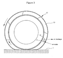
- FIG. 3 is a view for explaining a pumping principle of the compressed air pumping tire according to the first preferred embodiment
- FIG. 4 is a view showing a modification of the compressed air pumping tire according to the first preferred embodiment
- FIG. 5 is a view showing another modification of the compressed air pumping tire
- FIG. 6 is a conceptual view for showing a state where the compressed air pumping tire according to the first preferred embodiment is applied to a vehicle to obtain compressed air;
- FIG. 7 is a front view and a partially enlarged sectional view of a compressed air pumping tire according to a second preferred embodiment of the present invention.
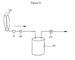
- FIG. 8 is a circuit diagram for showing a process to store the compressed air from the compressed air pumping tire according to the second preferred embodiment.
- a compressed air pumping tire 10 includes at least one air compression chamber 13 formed therein along the outer circumferential surface of a tire body, and pumps compressed air from the air compression chamber 13. That is, in the first preferred embodiment, the air compression chamber 13 is formed integrally with the tire body.
- the air compression chamber 13 includes at least one air intake hole 11 and at least one air discharge hole 12. So, as shown in FIG. 3 , while the tire 10 rolls on the road surface, a part of the tire, whose surface comes into contact with the road surface 1, is contracted and pushes the compressed air toward the air discharge hole 12. That is, the tire pumps air toward the air discharge hole 12 while compressing the air compression chamber 13 in the opposite direction to a rotational direction of the tire 10. In this instance, a part of the tire, which passed compression, is expanded and restored by an elastically restoring force of the tire body.
- the air compression chamber 13 may be one.
- the air compression chamber 13 is formed in a round band type.
- the air compression chamber 13 having the rectangular section includes a silicon-coated layer 13a formed on the inner surface thereof to prevent that the surfaces of the air compression chamber 13 are not stuck to each other when the air compression chamber 13 is restored after the contraction.
- the air compression chamber 13 may be adopted in such a way as to have a round section and to be helically wound on the circumference of the tire body at least once.
- the number of times that the air compression chamber 13 is wound on the tire body can be increased or decreased according to the width of the tire 10.
- the air intake hole 11 is provided at the front end of the air compression chamber 13 and the air discharge hole 12 is provided at the rear end of the air compression chamber 13. So, whenever the tire rotates twice, the volume of air in the air compression chamber 13 is reduced toward the air discharge hole 12 due to a pressure contact with the road surface to thereby generate compressed air.
- the air compression chamber 13 is formed inside a round projection portion 10a protrudingly formed along the outer circumferential surface of the tire body. Moreover, it would be appreciated that a number of the air compression chambers 13 are formed in such a way as to be helically wound on the tire body in the width direction of the tire several times.
- the air compression chamber 13 may be partitioned into a plurality of parts by at least one compression chamber partition 14.
- FIG. 4 illustrates a state where the air compression chamber 13 is partitioned into two parts by the partition 14, and the partitioned compression chambers 13 and 13 respectively have air intake holes 11 and 11 and air discharge holes 12 and 12.
- the air compression chamber 13 may further include ribs 15 mounted therein at regular intervals to enhance the restoring force of the contracted and deformed air compression chamber 13.
- the ribs 15 are mounted in a state where they are inclined at a fixed angle ( ⁇ ) in a radial direction so as not to interrupt running of the tire 10.
- a compressed air storing apparatus using the compressed air pumping tire 10 having the above configuration can be configured as follows. As shown in FIGS. 2 and 6 , a compressed air tank 20 for storing the air compressed in the air compression chamber 13 is connected to the air discharge hole 12 of the tire 10, and a check valve 35 for preventing a backflow of the compressed air is mounted on a flow channel for connecting the air discharge hole 12 with the compressed air tank 20. So, the compressed air stored in the compressed air tank 20 is shut out by the check valve 35, whereby it is prevented that the compressed air is introduced into the air compression chamber again.
- a pressure control valve 40 is mounted at an outlet of the compressed air tank 20 to keep the inside pressure of the compressed air tank 20 at a fixed setting pressure.
- a guide pipe 16 is connected to the air discharge hole 12 of the air compression chamber 13 to guide the compressed air, which is pumped from the air compression chamber 13, toward a central axis of a wheel of the tire 10, and a rotating joint 18 is connected to the guide pipe 16. So, even though the tire rotates on the road surface while the vehicle travels, the compressed air can be smoothly compressed to the tank 20 without any influence of the pipe.
- the compressed air storing apparatuses are selectively installed on two front wheel tires and/or two rear wheel tires, or on all four wheel tires as shown in FIG. 6 .
- a contact face is formed on a portion of the air compression chamber 13 in such a way that the portion of the air compression chamber 13 is contracted in a state where it is in contact with the road surface 1.
- the location of the contracted contact face is continuously changed in the air compression chamber 13 due to the rotation of the tire 10 while the vehicle travels.
- the capacity of the air compression chamber 13 is gradually reduced to thereby compress the air inside the air compression chamber 13.
- the air compressed in the air compression chamber 13 is stored into the compressed air tank 20 through the air discharge hole 12.
- the check valve 35 prevents the backflow of the compressed air stored into the compressed air tank 20.
- the compressed air stored in the compressed air tank 20 can be utilized to drive a necessary device, for example, a turbine connected to an engine.
- the pressure control valve 40 is opened so that the pressure lowers to the set pressure.
- a compressed air pumping tire includes at least one air-compressing tube 130 of at least one strip.
- the air-compressing tube 130 includes an air intake hole 131 and an air discharge hole 132 formed on the outer circumferential surface of the tire 10, and is made of flexible material, which is restorable after the compression.
- the number of the strips of the air-compressing tube 130 can be increased or decreased in consideration of the width of the tire 10.
- the air-compressing tube 130 of one strip or two strips can be wound on the outer circumferential surface of the tire 10 several times.
- the air-compressing tube 130 may have a section of a round form or another form. That is, in the second preferred embodiment of the present invention, it would be appreciated that the air-compressing tube 130 can be understood as an idea substituting for the air compression chamber 13 of the first preferred embodiment. In this instance, the air-compressing tube 130 is bonded on the tire body by a bonding means 137.
- a compressed air tank 120 is connected to the air discharge hole 132.
- a check valve 135 for preventing the backflow of the compressed air is mounted on a flow channel for connecting the air discharge hole 132 with the compressed air tank 120.
- a pressure control valve 140 is mounted at an outlet of the compressed air tank 120 to store the compressed air in a high-pressure state.
- the compressed air storing apparatus can be installed on all four wheels of the vehicle or selectively installed on the front wheels or the rear wheels.
- a structure of pipe line for connecting the air-compressing tube 130 and the tank 120 with each other is the same as the first preferred embodiment, its detailed description will be omitted.
- the present invention can simply pump the compressed air through the tire while the vehicle travels.
- the present invention can store the compressed air in the high-pressure state, whereby the stored compressed air can be effective utilized as energy for driving a necessary device.
- the compressed air is used as energy for rotating the turbine connected to the engine or energy for a turbo charger to thereby greatly reduce a fuel consumption of the engine.
Landscapes
- Engineering & Computer Science (AREA)
- Mechanical Engineering (AREA)
- General Engineering & Computer Science (AREA)
- Tires In General (AREA)
- Arrangement Or Mounting Of Propulsion Units For Vehicles (AREA)
- Compressors, Vaccum Pumps And Other Relevant Systems (AREA)
Applications Claiming Priority (1)
| Application Number | Priority Date | Filing Date | Title |
|---|---|---|---|
| KR1020070081028A KR100830166B1 (ko) | 2007-08-13 | 2007-08-13 | 압축공기 펌핑 타이어 및 이를 이용한 압축공기 저장장치 |
Publications (2)
| Publication Number | Publication Date |
|---|---|
| EP2025535A2 true EP2025535A2 (fr) | 2009-02-18 |
| EP2025535A3 EP2025535A3 (fr) | 2009-11-04 |
Family
ID=38658493
Family Applications (1)
| Application Number | Title | Priority Date | Filing Date |
|---|---|---|---|
| EP07018774A Withdrawn EP2025535A3 (fr) | 2007-08-13 | 2007-09-25 | Pneu de pompage d'air comprimé et appareil de stockage d'air comprimé utilisant celui-ci |
Country Status (5)
| Country | Link |
|---|---|
| US (1) | US20090044891A1 (fr) |
| EP (1) | EP2025535A3 (fr) |
| JP (1) | JP2009046108A (fr) |
| KR (1) | KR100830166B1 (fr) |
| CN (1) | CN101367321A (fr) |
Cited By (7)
| Publication number | Priority date | Publication date | Assignee | Title |
|---|---|---|---|---|
| EP2441597A1 (fr) * | 2010-10-18 | 2012-04-18 | The Goodyear Tire & Rubber Company | Pneu autogonflant |
| EP2607110A1 (fr) * | 2011-12-21 | 2013-06-26 | The Goodyear Tire & Rubber Company | Pneu comprenant un ensemble de connecteur |
| EP2607108A3 (fr) * | 2011-12-21 | 2014-01-15 | The Goodyear Tire & Rubber Company | Pneu et procédé de formation d'un passage d'air dans un pneu |
| EP2607109A3 (fr) * | 2011-12-21 | 2014-01-15 | The Goodyear Tire & Rubber Company | Pneu comprenant un ensemble connecteur et procédé de fabrication |
| EP2746071A3 (fr) * | 2012-12-18 | 2014-09-10 | The Goodyear Tire & Rubber Company | Pneu |
| EP2607107A3 (fr) * | 2011-12-21 | 2014-09-17 | The Goodyear Tire & Rubber Company | Pneu autogonflant et procédé de construction d'un pneu |
| US8955567B2 (en) | 2011-12-21 | 2015-02-17 | Richard B. O'Planick | Air maintenance tire and integral pump assembly |
Families Citing this family (37)
| Publication number | Priority date | Publication date | Assignee | Title |
|---|---|---|---|---|
| CZ303718B6 (cs) | 2006-05-23 | 2013-04-03 | Sithold S.R.O. | Komponenta s tvarovou pametí pro upravení tlaku v pneumatice a zpusob její výroby |
| WO2009103252A2 (fr) * | 2008-02-21 | 2009-08-27 | Coda Development, S.R.O. | Dispositif de réglage de pression de pneus |
| CZ2009748A3 (cs) * | 2009-11-11 | 2011-10-05 | Sithold S.R.O. | Zarízení pro transport vzduchu v pneumatice |
| US8534335B2 (en) | 2010-09-27 | 2013-09-17 | The Goodyear Tire & Rubber Company | Distributed pump self-inflating tire assembly |
| US8394311B2 (en) * | 2010-10-18 | 2013-03-12 | The Goodyear Tire & Rubber Company | Method of constructing a self-inflating tire |
| US8322036B2 (en) | 2010-11-22 | 2012-12-04 | The Goodyear Tire & Rubber Company | Method of manufacturing a self-inflating tire |
| US8550137B2 (en) | 2010-11-22 | 2013-10-08 | The Goodyear Tire & Rubber Company | Tire for self-inflating tire system |
| US8235081B2 (en) | 2010-11-22 | 2012-08-07 | The Goodyear Tire & Rubber Company | In-line pumping assembly for self-inflating tire |
| US8662127B2 (en) | 2010-12-22 | 2014-03-04 | The Goodyear Tire & Rubber Company | Pump and actuator assembly for a self-inflating tire |
| US8651155B2 (en) | 2011-03-23 | 2014-02-18 | The Goodyear Tire & Rubber Company | Hydraulic piston pump assembly for air maintenance tire |
| US8656972B2 (en) | 2011-03-23 | 2014-02-25 | The Goodyear Tire & Rubber Company | Hydraulic membrane pump assembly for air maintenance tire |
| WO2013009583A2 (fr) * | 2011-07-08 | 2013-01-17 | Pumptire Ag | Pneumatique auto-gonflable |
| US9278584B2 (en) * | 2011-10-31 | 2016-03-08 | Innovative Technologies, Llc | All-weather tire |
| US9290057B2 (en) * | 2011-10-31 | 2016-03-22 | Innovative Technologies, Llc | All season safety tire |
| US8820369B2 (en) * | 2011-11-09 | 2014-09-02 | The Goodyear Tire & Rubber Company | Self-inflating tire |
| CZ2011757A3 (cs) * | 2011-11-22 | 2013-05-29 | Sithold S.R.O | Zarízení pro udrzování a zmenu tlaku v pneumatice |
| US8852371B2 (en) * | 2011-12-21 | 2014-10-07 | The Goodyear Tire & Rubber Company | Method of forming an air passageway in an air maintenance tire |
| US9108476B2 (en) * | 2012-07-19 | 2015-08-18 | The Goodyear Tire & Rubber Company | Bypass air maintenance tire and pump assembly |
| US9381781B2 (en) | 2012-07-30 | 2016-07-05 | The Goodyear Tire & Rubber Company | Bonding to a pneumatic tire |
| US8944126B2 (en) | 2012-07-30 | 2015-02-03 | The Goodyear Tire & Rubber Company | Filter for a pneumatic tire |
| US10052834B2 (en) | 2012-10-16 | 2018-08-21 | The Goodyear Tire & Rubber Company | Protective structure for a retreaded air maintenance tire |
| US20140110029A1 (en) * | 2012-10-24 | 2014-04-24 | Robert Leon Benedict | Vein pump assembly for air maintenance tire |
| US9669671B2 (en) | 2012-10-24 | 2017-06-06 | The Goodyear Tire & Rubber Company | Vein pump assembly for air maintenance tire |
| WO2014189795A1 (fr) * | 2013-05-23 | 2014-11-27 | Michel Energy, Inc. | Pneus de compression et systèmes de pneumatique |
| CN103818245A (zh) * | 2014-01-30 | 2014-05-28 | 冯柯霖 | 一种轮胎受力发电装置 |
| CN103818246A (zh) * | 2014-01-30 | 2014-05-28 | 冯柯霖 | 一种车轮能量转换发电系统 |
| CN103818247A (zh) * | 2014-01-30 | 2014-05-28 | 冯柯霖 | 一种轮胎能量转换系统 |
| CN103821683A (zh) * | 2014-01-30 | 2014-05-28 | 冯柯霖 | 一种安装在轮胎内的能量转换系统 |
| ES2718974T3 (es) * | 2014-04-04 | 2019-07-05 | Benjamin J Krempel | Mecanismo de bombeo autoinflable |
| US9809066B2 (en) | 2014-05-05 | 2017-11-07 | The Goodyear Tire & Rubber Company | System for an air maintenance tire assembly |
| US9505276B2 (en) | 2014-12-05 | 2016-11-29 | The Goodyear Tire & Rubber Company | Filter for a pneumatic tire |
| US20180361807A1 (en) * | 2015-12-30 | 2018-12-20 | Benjamin J. Krempel | Flat Compression Pump |
| CN105889043A (zh) * | 2016-04-12 | 2016-08-24 | 江门麦加道机电厂有限公司 | 一种低噪音及发热低的气泵 |
| CN119636301A (zh) * | 2019-05-09 | 2025-03-18 | 中山市华宝勒生活用品有限公司 | 一种可自动补气的充气轮胎 |
| CN112572146A (zh) * | 2020-11-17 | 2021-03-30 | 蔡梦雄 | 一种基于车轮行进的能量收集系统 |
| CN112549949A (zh) * | 2020-12-29 | 2021-03-26 | 深圳市界峰科技有限公司 | 动力系统和车辆 |
| TWI862086B (zh) * | 2023-08-17 | 2024-11-11 | 和碩聯合科技股份有限公司 | 輪胎結構 |
Family Cites Families (19)
| Publication number | Priority date | Publication date | Assignee | Title |
|---|---|---|---|---|
| US1050886A (en) * | 1910-02-23 | 1913-01-21 | Anson B Wetherell | Vehicle-tire. |
| US1134361A (en) * | 1912-02-13 | 1915-04-06 | Anson B Wetherell | Self-filling tire. |
| US1330072A (en) * | 1919-07-23 | 1920-02-10 | William L Geddes | Automatic pump |
| US2095489A (en) * | 1934-09-13 | 1937-10-12 | Cotton George Albert | Pneumatic tire |
| DE812515C (de) * | 1949-06-21 | 1953-08-24 | Max Kastner | Geraet zur Erzeugung von Druckluft durch den Raddruck von Fahrzeugen |
| JPS5675978A (en) * | 1979-11-27 | 1981-06-23 | Kunio Harada | Power generating method by utilizing rotation of tire |
| US4432405A (en) * | 1982-09-27 | 1984-02-21 | Harold Grushkin | Pressure cuff tire pump device |
| US4570691A (en) * | 1984-05-03 | 1986-02-18 | Martus Donald G | Tire pressure regulation system |
| US4651792A (en) * | 1984-07-02 | 1987-03-24 | Allen F. Ehle | Automatic tire pressurizing system |
| DE3607369A1 (de) * | 1986-03-06 | 1987-09-10 | Bosch Gmbh Robert | Vorrichtung zur reifendruckregelung |
| US4840212A (en) * | 1987-06-16 | 1989-06-20 | Wei Yung Kuan | Automatic air pump for wheel tires |
| KR900005670A (ko) * | 1988-09-03 | 1990-04-14 | 서경득 | 차체하중을 이용한 발전장치 및 그를 이용한 동력장치 |
| FR2700143B1 (fr) * | 1993-01-05 | 1995-09-29 | Demaillat Yves Marc | Roue dynamique. |
| GB2284918B (en) * | 1993-12-17 | 1997-05-21 | Fuji Heavy Ind Ltd | Inflation pressure sensor for automobile pneumatic tyre |
| JPH10218075A (ja) | 1997-02-07 | 1998-08-18 | Teruji Yokota | 空気圧利用自転車 |
| US7051778B2 (en) * | 2000-12-22 | 2006-05-30 | Pirelli Pneumatici S.P.A. | Device and method for generating energy in a rolling wheel |
| KR200285704Y1 (ko) | 2002-05-20 | 2002-08-13 | 이광선 | 발전동력용 공압 발생장치 |
| KR200292339Y1 (ko) | 2002-06-05 | 2002-10-19 | 장종근 | 주행중인 자동차 하중을 이용한 압축공기 생성장치 |
| US7322392B2 (en) * | 2005-06-17 | 2008-01-29 | Delphi Technologies, Inc. | Tire pump |
-
2007
- 2007-08-13 KR KR1020070081028A patent/KR100830166B1/ko not_active Expired - Fee Related
- 2007-09-17 US US11/901,455 patent/US20090044891A1/en not_active Abandoned
- 2007-09-25 EP EP07018774A patent/EP2025535A3/fr not_active Withdrawn
- 2007-10-12 CN CNA2007101525806A patent/CN101367321A/zh active Pending
- 2007-10-16 JP JP2007269122A patent/JP2009046108A/ja active Pending
Cited By (12)
| Publication number | Priority date | Publication date | Assignee | Title |
|---|---|---|---|---|
| EP2441597A1 (fr) * | 2010-10-18 | 2012-04-18 | The Goodyear Tire & Rubber Company | Pneu autogonflant |
| CN102452283A (zh) * | 2010-10-18 | 2012-05-16 | 固特异轮胎和橡胶公司 | 自充气轮胎组件 |
| US8291950B2 (en) | 2010-10-18 | 2012-10-23 | The Goodyear Tire & Rubber Company | Self-inflating tire assembly |
| CN102452283B (zh) * | 2010-10-18 | 2014-08-20 | 固特异轮胎和橡胶公司 | 自充气轮胎组件 |
| EP2607110A1 (fr) * | 2011-12-21 | 2013-06-26 | The Goodyear Tire & Rubber Company | Pneu comprenant un ensemble de connecteur |
| EP2607108A3 (fr) * | 2011-12-21 | 2014-01-15 | The Goodyear Tire & Rubber Company | Pneu et procédé de formation d'un passage d'air dans un pneu |
| EP2607109A3 (fr) * | 2011-12-21 | 2014-01-15 | The Goodyear Tire & Rubber Company | Pneu comprenant un ensemble connecteur et procédé de fabrication |
| EP2607107A3 (fr) * | 2011-12-21 | 2014-09-17 | The Goodyear Tire & Rubber Company | Pneu autogonflant et procédé de construction d'un pneu |
| US8875762B2 (en) | 2011-12-21 | 2014-11-04 | The Goodyear Tire & Rubber Company | Air maintenance tire and elbow connector system |
| US8955567B2 (en) | 2011-12-21 | 2015-02-17 | Richard B. O'Planick | Air maintenance tire and integral pump assembly |
| EP2746071A3 (fr) * | 2012-12-18 | 2014-09-10 | The Goodyear Tire & Rubber Company | Pneu |
| US9050858B2 (en) | 2012-12-18 | 2015-06-09 | The Goodyear Tire & Rubber Company | Peristaltic pump air maintenance tire |
Also Published As
| Publication number | Publication date |
|---|---|
| CN101367321A (zh) | 2009-02-18 |
| US20090044891A1 (en) | 2009-02-19 |
| EP2025535A3 (fr) | 2009-11-04 |
| KR20070093934A (ko) | 2007-09-19 |
| JP2009046108A (ja) | 2009-03-05 |
| KR100830166B1 (ko) | 2008-05-20 |
Similar Documents
| Publication | Publication Date | Title |
|---|---|---|
| EP2025535A2 (fr) | Pneu de pompage d'air comprimé et appareil de stockage d'air comprimé utilisant celui-ci | |
| EP2578420B1 (fr) | Pneu comprenant un ensemble tube et procédé d'assemblage d'un tube d'air allongé à l'intérieur d'un pneumatique | |
| JP6388468B2 (ja) | 空気タイヤ及びその製造方法 | |
| EP2343200B1 (fr) | Pneu autogonflant | |
| EP2565060B1 (fr) | Pneu autogonflant | |
| RU2106978C1 (ru) | Пневматическая шина с автоматической подкачкой воздуха | |
| EP2565059A2 (fr) | Pneu | |
| EP2567834B1 (fr) | Pneu comprenant un passage d'air dans une rainure de paroi latérale | |
| US8695661B2 (en) | Air maintenance pumping tube and tire assembly | |
| EP2543524A1 (fr) | Ensemble de pompage de maintenance d'air et pneu | |
| JP2013506803A (ja) | 拡張可能なアキュムレータおよびリザーバの組立体を含むエネルギ貯蔵システム | |
| EP3012125B1 (fr) | Ensemble de maintenance a air d'un pneu | |
| US3176622A (en) | Pump | |
| US20150137420A1 (en) | Securing to a pneumatic tire | |
| US20150375575A1 (en) | Vein pump assembly for air maintenance tire | |
| CN108571472A (zh) | 可变压缩机 | |
| CN104339995B (zh) | 用于空气维持轮胎的阀组件 | |
| US9688109B2 (en) | Filter for a pneumatic tire | |
| EP2957439A1 (fr) | Système de pompage d'air et pneumatique | |
| JPH09257184A (ja) | 脈動吸収ホース | |
| EP3112192A1 (fr) | Pneu | |
| CN105383233A (zh) | 空气维持泵送组件和轮胎 |
Legal Events
| Date | Code | Title | Description |
|---|---|---|---|
| PUAI | Public reference made under article 153(3) epc to a published international application that has entered the european phase |
Free format text: ORIGINAL CODE: 0009012 |
|
| AK | Designated contracting states |
Kind code of ref document: A2 Designated state(s): AT BE BG CH CY CZ DE DK EE ES FI FR GB GR HU IE IS IT LI LT LU LV MC MT NL PL PT RO SE SI SK TR |
|
| AX | Request for extension of the european patent |
Extension state: AL BA HR MK RS |
|
| RAP1 | Party data changed (applicant data changed or rights of an application transferred) |
Owner name: GOH, PILL-KUEN |
|
| PUAL | Search report despatched |
Free format text: ORIGINAL CODE: 0009013 |
|
| AK | Designated contracting states |
Kind code of ref document: A3 Designated state(s): AT BE BG CH CY CZ DE DK EE ES FI FR GB GR HU IE IS IT LI LT LU LV MC MT NL PL PT RO SE SI SK TR |
|
| AX | Request for extension of the european patent |
Extension state: AL BA HR MK RS |
|
| RIC1 | Information provided on ipc code assigned before grant |
Ipc: F04B 43/12 20060101ALI20090928BHEP Ipc: B60C 11/00 20060101ALI20090928BHEP Ipc: B60C 23/00 20060101AFI20071116BHEP |
|
| AKX | Designation fees paid | ||
| STAA | Information on the status of an ep patent application or granted ep patent |
Free format text: STATUS: THE APPLICATION IS DEEMED TO BE WITHDRAWN |
|
| 18D | Application deemed to be withdrawn |
Effective date: 20100505 |
|
| REG | Reference to a national code |
Ref country code: DE Ref legal event code: 8566 |