EP2025576A2 - Dispositif de réglage de position de volant de direction - Google Patents
Dispositif de réglage de position de volant de direction Download PDFInfo
- Publication number
- EP2025576A2 EP2025576A2 EP08158110A EP08158110A EP2025576A2 EP 2025576 A2 EP2025576 A2 EP 2025576A2 EP 08158110 A EP08158110 A EP 08158110A EP 08158110 A EP08158110 A EP 08158110A EP 2025576 A2 EP2025576 A2 EP 2025576A2
- Authority
- EP
- European Patent Office
- Prior art keywords
- collar member
- width direction
- shock
- absorbing material
- stopper shock
- Prior art date
- Legal status (The legal status is an assumption and is not a legal conclusion. Google has not performed a legal analysis and makes no representation as to the accuracy of the status listed.)
- Granted
Links
- 239000011359 shock absorbing material Substances 0.000 claims abstract description 75
- 230000000149 penetrating effect Effects 0.000 claims abstract description 3
- 230000035939 shock Effects 0.000 abstract description 15
- 238000010586 diagram Methods 0.000 description 16
- 229920003002 synthetic resin Polymers 0.000 description 3
- 239000000057 synthetic resin Substances 0.000 description 3
- 238000010521 absorption reaction Methods 0.000 description 1
- 239000002775 capsule Substances 0.000 description 1
- 230000008878 coupling Effects 0.000 description 1
- 238000010168 coupling process Methods 0.000 description 1
- 238000005859 coupling reaction Methods 0.000 description 1
- 239000013013 elastic material Substances 0.000 description 1
- 239000000463 material Substances 0.000 description 1
- 239000002184 metal Substances 0.000 description 1
- 238000003466 welding Methods 0.000 description 1
Images


Classifications
-
- B—PERFORMING OPERATIONS; TRANSPORTING
- B62—LAND VEHICLES FOR TRAVELLING OTHERWISE THAN ON RAILS
- B62D—MOTOR VEHICLES; TRAILERS
- B62D1/00—Steering controls, i.e. means for initiating a change of direction of the vehicle
- B62D1/02—Steering controls, i.e. means for initiating a change of direction of the vehicle vehicle-mounted
- B62D1/16—Steering columns
- B62D1/18—Steering columns yieldable or adjustable, e.g. tiltable
- B62D1/184—Mechanisms for locking columns at selected positions
Definitions
- the present invention relates to a steering wheel position adjustment device in which a stopper shock-absorbing material for absorbing shocks during tilt/telescopic adjustment can be mounted on a predetermined position extremely easily and shock-absorbing capacity for tilt/telescopic adjustment can be improved in a steering device having a tilt/telescopic adjustment mechanism.
- a steering device with a tilt/telescopic adjustment mechanism which is capable of adjusting the position of the steering wheel vertically and longitudinally in accordance with the physical constitution of a driver, has been conventionally frequently used (see Unexamined Utility Model Application Publication S64-28365 and Japanese Published Unexamined Patent Application No. 2006-240327 ).
- this steering device having a tilt/telescopic adjustment mechanism tilting and telescopic long holes are formed in a bracket portion, and a lock lever shaft and the like which penetrate through these long holes are inserted and disposed.
- the problem in this structure is that when a metallic bolt is moved along the long holes, end surfaces of the long holes, also made of metal, collide with the bolt at a tilt/telescopic operation limit position, thereby causing metallic clank and impairing quietness and soft operational touch in the operation limit position when the bolt and the end surfaces of the long holes hit against each other.
- the stopper shock-absorbing material made of a rubber, a synthetic resin or the like was attached, whereby it was possible to absorb shocks and realize quietness.
- An object of the present invention is to improve operational feeling when performing the adjustment, and particularly to reduce shocks and impact noises that are caused at the time of operation.
- the inventors have conducted keen research and, as a result, solved the problem by configuring the invention as a steering wheel position adjustment device, comprising: a movable bracket having adjusting long holes on both sides in a width direction of the movable bracket; a fixed bracket; a lock shaft penetrating through both of the adjusting long holes to support the movable bracket to the fixed bracket; a collar member which is rotatably supported within the movable bracket by the lock shaft and is capable of moving along, with the lock shaft, in a longitudinal direction; and stopper shock-absorbing materials, which are attached to both side sections in the longitudinal direction of the adjusting long holes within the movable bracket, and each of which is formed thereon with an abutment surface against which the collar member abuts, wherein when each of the stopper shock-absorbing materials and the collar member abut against each other, both end portions in a width direction of the abutted surface of the stopper shock-absorbing material are first brought into abut
- the abutted surface of the stopper shock-absorbing material abuts against the collar member during tilt/telescopic adjustment in a step in which the both end portions in the width direction of the abutted surface are first brought into abutment against collar member, and then the central section in the width direction of the abutted surface abuts against or comes close to the collar member.
- the both end portions in the width direction of the abutted surface are elastically deformed by abutting against the collar member, and shocks are temporally dispersed as compared with the ordinary case where the entire abutted surface abuts against the collar member at once, whereby the shock force generated when the collar member and the stopper shock-absorbing material hit against each other can be further reduced and quietness and operational touch in telescopic adjustment can be improved.
- a cylindrical shape portion is formed in a central portion in an axial direction of the collar member and conical portions are formed such that a diameter of each of the conical portions gradually increases toward both ends in a width direction of the cylindrical shape portion, and wherein both of the end portions in the width direction of the abutment surface of the stopper shock-absorbing material abut against the conical portion.
- the cylindrical shape portion is formed in the central portion in the axial direction of the collar member, the conical portions are formed on both sides in the width direction of the cylindrical shape portion, respectively, such that the diameters of the conical portions gradually increase toward respective end portions in the axial direction of the collar member, and the width direction of the abutted surface of the stopper shock-absorbing material is formed to be larger than that of the cylindrical shape portion. Accordingly, since the both end portions in the width direction of the stopper shock-absorbing material are brought into abutment against the conical portions of the collar member, the both end portions in the width direction of the abutted surface in particular are elastically deformed significantly, whereby shock absorption is extremely improved and quietness and operational touch in telescopic adjustment can also be improved.
- the central portion in the axial direction of the collar member is a smallest diameter portion, and a cross-sectional shape of the collar member along the axial direction is formed in a substantially arched shape such that the diameter thereof gradually increases toward both sides in the axial direction.
- the central portion in the axial direction of the collar member is configured as a smallest diameter portion, and a cross-sectional shape along the axial direction of the collar member is formed in a substantially arched shape such that the diameter thereof gradually increases toward the both sides in the axial direction. Accordingly, the both end portions and central portion in the width direction of the stopper shock-absorbing material can be entirely brought into abutment against the collar member smoothly, whereby quietness can be achieved.
- the abutted surface may have a substantially concave arched cross section in the width direction thereof. Therefore, it is sufficient that the collar member be formed into a cylindrical shape only so that a simple structure can be obtained.
- Edge projecting portions may be formed on the both end portions in the width direction of the abutted surface of the stopper shock-absorbing material.
- the collar member be formed into a cylindrical shape only so that a simple structure can be obtained.
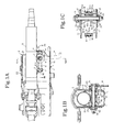
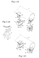
- the present invention is mainly configured by a movable bracket 1, a fixed bracket 2, a collar member 6, and stopper shock-absorbing materials 8.
- Supporting side portions 11, 11 are formed on both sides in a width direction of the movable bracket 1.
- a bottom surface portion 12 which integrally couples the both supporting side portions 11, 11 together is formed underneath.
- a steering column 3 is disposed at upper end positions of the both supporting side portions 11, 11, and this steering column 3 is welded and fixed in a state such as to be roughly held between the both supporting side portions 11, 11 (see Fig. 1B ).
- Adjusting long holes 13, 13 for performing telescopic adjustment are formed on the both supporting side portions 11, 11 of the movable bracket 1. Each adjusting long hole 13 is formed along a longer direction of the steering column 3 attached to the movable bracket 1.
- the fixed bracket 2 is a component which attaches the movable bracket 1 to a predetermined position within a vehicle and for performing tilt/telescopic adjustment.
- the fixed bracket 2 is configured by a pair of right and left fixed supporting side plates 21, 21 and an attachment apex 22.
- the fixed bracket 2 is attached to a predetermined position within the vehicle via a capsule member and is configured to be capable of absorbing shock energy generated at the time of collision and the like.
- tilt adjusting holes 23, 23 are formed on the both fixed supporting side plates 21, 21 of the fixed bracket 2.
- the positions of the tilt adjusting holes 23, 23 are aligned with the positions of the adjusting long holes 13, 13 of the movable bracket 1, and a lock shaft 5 is inserted into these holes (see Fig. 1B ).
- the both supporting side portions 11, 11 are attached in a state such as to be held between the both fixed supporting side plates 21, 21 of the fixed bracket 2 so that the both supporting side portions 11, 11 can be tightened and fixed by the lock shaft 5 (see Fig. 1B ).
- the lock shaft 5 locks (tightens) and unlocks steering during tilt/telescopic adjustment, and further serves to support the collar member 6 between the both supporting side portions 11, 11.
- the collar member 6 can freely move along with the lock shaft 5 through the adjusting long hole 13 in the longer direction.
- An operation lever 4 for performing tilt/telescopic adjustment is attached to the lock shaft 5 for tightening and releasing purposes.
- the lock shaft 5 is in the form of a bolt on which an outer screw portion 51 is formed, and is provided for tightening and releasing by means of a nut member 52, a cam member 53 and the like (see Fig. 1B ).
- attachment tools 7 are members which serve to dispose and attach stopper shock-absorbing materials 8 in the movable bracket 1.
- the attachment tools 7 are disposed so as to be placed within the movable bracket 1 and at both side sections in the longitudinal direction of the adjusting long hole 13, respectively.
- the attachment tools 7 are fixed to the steering column 3 by welding means, the steering column 3 being fixed to the movable bracket 1 (see Fig. 11A ).
- the longitudinal direction means a direction which matches the longer direction or axial direction of the steering column 3, and corresponds to a horizontal direction which follows the longer direction of the steering column 3 in Fig. 1A .
- the attachment tools 7 are placed along the longitudinal direction within the movable bracket 1 and, more specifically, attached so as to be placed in both end sections in the longer direction of the adjusting long hole 13 formed in the movable bracket 1 (see Fig. 2A ).
- the stopper shock-absorbing materials 8, 8 are attached to the both attachment tools 7, 7 respectively, which are attached in the longitudinal direction. Accordingly, when the movable bracket 1 and the adjusting long holes 13 are moved in the longitudinal direction with reference to the shaft portion of the lock shaft 5 coupling the movable bracket 1 and the fixed bracket 2 together, the collar member 6 which is rotatably supported by the lock shaft 5 abuts against each of the stopper shock-absorbing materials 8 without abutting directly against the both ends in the longer direction of the adjusting long holes 13.
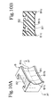
- the collar member 6 is formed into a substantially hollow cylindrical shape as shown in Fig. 1C , Fig. 2 and the like.
- a cylindrical shape portion 61 is formed in the central section in the axial direction, and conical portions 62, 62 are formed on both sides in the width direction of the cylindrical shape portion 61.
- the cylindrical shape portion 61 configures a cylindrical shape section whose diameter is constant throughout the region forming the cylindrical shape portion 61 along the axial direction.
- Each conical portion 62 is formed into a conical shape such that the diameter thereof gradually increases toward the end portions in the axial direction of the collar member 6.
- a rotatably supporting through-hole 63 is formed in the central position in the diameter direction of the collar member 6.
- the collar member 6 has the shape of a substantially bobbin and is symmetric with respect to the center in the axial direction.
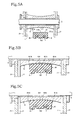
- the configuration of the collar member 6 according to the second embodiment is substantially the same as that of the collar member 6 according to the first embodiment, as shown in Fig. 5 , but the central section in the axial direction is formed as a smallest diameter portion 64, which is formed such that the diameter thereof gradually increases toward the both sides in the axial direction. Furthermore, the outer circumference of the collar member 6 along the axial direction is formed into a substantially arched shape which curves at the central section in the axial direction. Moreover, the collar member 6 according to the third embodiment is formed into a complete cylindrical shape, as shown in Fig. 6 and Fig. 7 . Specifically, the collar member 6 is formed such that the diameter thereof is constant throughout the whole position along the axial direction.
- Each stopper shock-absorbing material 8 is configured mainly by an elastic main body portion 81 and a projecting portion 82.
- the stopper shock-absorbing material 8 is formed by an elastic material, such as a rubber or synthetic resin, and is integrally formed by the elastic main body portion 81 and the projecting portion 82.
- the elastic main body portion 81 is formed into a substantially thick plate shape and configures an abutted surface 811, which is the surface abutting against the collar member 6.
- the abutted surface 811 is formed into substantially rectangular or square shape.
- Both end sides in a width direction of the abutted surface 811 are first brought into abutment against the collar member 6, and after a certain time interval the central section in the width direction of the abutted surface 811 abuts against or comes close to the collar member 6.
- End portions 811a, 811a on both sides in the width direction of the abutted surface 811 are the sections which are brought into abutment first when the collar member 6 and the stopper shock-absorbing material 8 about against each other.
- a central portion 811b in the width direction of the abutted surface 811 abuts against or comes close to the collar member 6 after the both of the end portions 811a, 811a abut against the collar member 6 (see Figs. 4A through 4C , Fig. 5 through Fig. 7 , and the like).
- the central portion 811b of the stopper shock-absorbing material 8 indicates the central point and the area adjacent thereto in the axial direction.
- the abutted surface 811 is formed as a concave surface having a substantially arched cross-sectional shape along the vertical direction thereof.
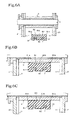
- the radius of curvature of the concave arched surface between the both ends in the width direction of the abutted surface 811 and in the vertical direction of the same is substantially equal to the diameter of the cylindrical shape portion 61 of the collar member 6: that is, the concave arched surface is formed such that its radius of curvature is substantially equal to the diameter of the section where the collar member 6 and the abutted surface 811 abut against each other (see Fig. 8C ).
- the arched surface is formed such that the axial direction thereof follows the width direction of the elastic main body portion 81.
- the projecting portion 82 of the stopper shock-absorbing material 8 is formed into a substantially flat cylindrical shape and formed so as to project in a substantially perpendicular direction from the rear surface of the elastic main body portion 81.
- a guide groove 71 and a fitting hole 72 into which the projecting portion 82 of the stopper shock-absorbing material 8 is inserted and fitted are formed in each attachment tool 7 (see Fig. 11B ), whereby the projecting portion 82 of the stopper shock-absorbing material 8 is guided by the guide groove 71 and fitted and fixed into the fitting hole 72 (see Figs. 11A through 11C ).
- the abutted surface 811 of the stopper shock-absorbing material 8 there are various embodiments in accordance with the shape of the collar member 6 of the first through third embodiments.
- the abutted surface 811 is formed to have the same arched cross-sectional shape along the width direction (see Fig. 4 , Fig. 8 ).
- the size in the width direction of the abutted surface 811 is represented as Wa.
- the size in the axial direction of the cylindrical shape portion 61 of the collar member 6 is represented as La, and the size between the outermost ends of the respective conical portions 62, 62 as Lb.
- the size Wa is set to be larger than the size La and smaller than the size Lb. Specifically, La ⁇ Wa ⁇ Lb is established (see Fig. 2B ).
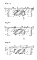
- the collar member 6 When telescopic adjustment is performed in such a combination of the collar member 6 and the stopper shock-absorbing materials 8, the collar member 6 is first moved toward either one of the stopper shock-absorbing materials 8 in the longitudinal direction, and, at the instant of abutment of the collar member 6, the both end portions 811a, 811a in the width direction of the abutted surface 811 first abut against the inclined surfaces of the conical portions 62, 62, respectively.
- the stopper shock-absorbing material 8 gradually abuts (or sometimes only comes close) such that the central portion 811b in the width direction of the abutted surface 811 comes close to the cylindrical shape portion 61 as the both end portions 811a, 811a in the width direction of the abutted surface 811 are elastically deformed.
- the central section in the width direction of the abutted surface 811 abuts against or comes close to the cylindrical shape portion 61, while the both ends in the width direction of the abutted surface 811 of the stopper shock-absorbing material 8 start to abut against the both conical portions 62, 62 of the collar member 6, respectively.
- the both end sections in the width direction of the abutted surface 811 which is elastically deformed easily abut against the conical portions 62, 62 of the collar member 6, respectively, whereby the stopper shock-absorbing material 8 is subjected to not only compressional deformation but also shear deformation at an early stage of abutment between the stopper shock-absorbing material 8 and the collar member 6. Therefore, as compared with the ordinary case where the entire abutted surface 811 abuts against the collar member 6 at once, the amount of deformation of the abutted surface 811 can be increased and more shock load can be absorbed.
- a so-called second-stage abutment operation is performed in which, at the instant of abutment between the collar member 6 and the stopper shock-absorbing material 8, the both end portions 811a, 811a of the abutted surface 811 abut against the collar member 6 first, and after a certain time interval the central portion 811b of the abutted surface 811 abuts against the outer circumferential surface of the collar member 6 (see Fig. 4 ). Accordingly, quietness in abutment can be secured. Therefore, the shock force generated when the collar member 6 and the stopper shock-absorbing material 8 hit against each other during telescopic adjustment can be further reduced, and quietness and operational touch in telescopic adjustment can be improved.
- the stopper shock-absorbing materials 8 of the first embodiment are applied to a collar member 6 of the second embodiment, and in this case the abutted surface 811 is formed to have the same arched cross-sectional shape along the width direction (see Fig. 5A ).
- the cylindrical shape portion 61 and the both conical portions 62, 62 are not formed explicitly, but the central portion in the axial direction of the collar member 6 is formed as the curving smallest diameter portion 64.
- the step of abutting the both end portions 811a, 811a in the with direction first and then the central portion 811b of the abutted surface 811 of the stopper shock-absorbing material 8 has continuity and allows extremely quiet telescopic adjustment operation.
- stopper shock-absorbing materials 8 of the second embodiment which are applied to a collar member 6 of the third embodiment are each formed such that the both end sections in the width direction of the abutted surface 811 project.
- Each edge projecting portion 811c is formed to have a substantially triangular cross-sectional shape.
- the central portion 811b between the edge projecting portions 811c, 811c forms a flat surface, i.e., a cylindrical shape.
- Either type is formed such that the both end portions 811a, 811a of the abutted surface 811 project more than the central portion 811b in the width direction.
- the collar member 6 When telescopic adjustment is performed in such a combination of the collar member 6 and the stopper shock-absorbing materials 8, the collar member 6 is first moved toward either one of the stopper shock-absorbing materials 8 in the longitudinal direction, and, at the instant of abutment between the stopper shock-absorbing material 8 and the collar member 6, the both end portions 811a, 811a in the width direction of the abutted surface 811 of the first type first abut against the outer circumferential surface of the cylindrical collar member 6. Then, the both end portions 811a, 811a are compressed while being elastically deformed, and then the central portion 811b abuts against (or sometimes only comes close to) the outer circumferential surface of the collar member 6 (see Figs. 6B and 6C ).
- the both edge projecting portions 811c, 811c in the width direction of the abutted surface 811 first abut against the outer circumferential surface of the cylindrical collar member 6. Then, the both edge projecting portions 811c, 811c are compressed while being elastically deformed, and then the central portion 811b abuts against (or sometimes only comes close to) the outer circumferential surface of the collar member 6 (see Figs. 7B and 7C ). Then, the shock force generated when the collar member 6 and the stopper shock-absorbing material 8 hit against each other during telescopic adjustment can be further reduced, and quietness and operational touch in telescopic adjustment can be improved.
- the stopper shock-absorbing materials 8 of the first and second embodiments were illustrated as the stopper shock-absorbing materials 8 applied to the collar members 6 of the first through third embodiments, but the combination of these components is not limited to the combinations described above. Therefore, the combination of the collar members 6 of the first through third embodiments and the stopper shock-absorbing materials 8 of the first and second embodiments may be set arbitrarily, and, for example, the stopper shock-absorbing materials 8 of the second embodiment can be applied to the collar member 6 of the first embodiment.
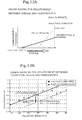
- Fig. 12 is a graph showing the characteristics of the present invention.
- the graph of Fig. 12A shows that the performances drawn in thick lines can be achieved at the point of a post-countermeasure at which the present invention is applied.
- This post-countermeasure shows that the stroke between when the collar member 6 and the stopper shock-absorbing material 8 abut against each other and when they stop is extended. Therefore, this graph shows that generation G, i.e., a shock, between a pre-countermeasure and the post-countermeasure, is reduced.
- Fig. 12B shows the magnitude of a shock which is caused by the difference in telescopic speeds of abutment between the collar member 6 and the stopper shock-absorbing material 8 during telescopic adjustment. According to the present invention, the shock generated by the abutment is reduced at all telescopic speeds.
Landscapes
- Engineering & Computer Science (AREA)
- Chemical & Material Sciences (AREA)
- Combustion & Propulsion (AREA)
- Transportation (AREA)
- Mechanical Engineering (AREA)
- Steering Controls (AREA)
- Vibration Dampers (AREA)
Applications Claiming Priority (1)
| Application Number | Priority Date | Filing Date | Title |
|---|---|---|---|
| JP2007212984A JP4435219B2 (ja) | 2007-08-17 | 2007-08-17 | ステアリングホィールの位置調整装置 |
Publications (3)
| Publication Number | Publication Date |
|---|---|
| EP2025576A2 true EP2025576A2 (fr) | 2009-02-18 |
| EP2025576A3 EP2025576A3 (fr) | 2009-09-30 |
| EP2025576B1 EP2025576B1 (fr) | 2012-03-07 |
Family
ID=40010811
Family Applications (1)
| Application Number | Title | Priority Date | Filing Date |
|---|---|---|---|
| EP08158110A Not-in-force EP2025576B1 (fr) | 2007-08-17 | 2008-06-12 | Dispositif de réglage de position de volant de direction |
Country Status (5)
| Country | Link |
|---|---|
| US (1) | US8051742B2 (fr) |
| EP (1) | EP2025576B1 (fr) |
| JP (1) | JP4435219B2 (fr) |
| CN (1) | CN101367402B (fr) |
| ES (1) | ES2382172T3 (fr) |
Cited By (2)
| Publication number | Priority date | Publication date | Assignee | Title |
|---|---|---|---|---|
| DE102012100626B3 (de) * | 2012-01-25 | 2013-02-21 | Thyssenkrupp Presta Aktiengesellschaft | Lenksäule für ein Kraftfahrzeug |
| EP2765057A4 (fr) * | 2011-09-29 | 2015-06-03 | Nsk Ltd | Dispositif de direction télescopique |
Families Citing this family (17)
| Publication number | Priority date | Publication date | Assignee | Title |
|---|---|---|---|---|
| JP2010228681A (ja) * | 2009-03-27 | 2010-10-14 | Yamada Seisakusho Co Ltd | ステアリング装置 |
| JP5428582B2 (ja) * | 2009-06-30 | 2014-02-26 | 日本精工株式会社 | ステアリング装置 |
| JP5662115B2 (ja) * | 2010-01-20 | 2015-01-28 | 株式会社山田製作所 | ステアリング装置 |
| DE102011050683A1 (de) * | 2011-05-27 | 2012-11-29 | Thyssenkrupp Presta Aktiengesellschaft | Lenksäule für ein Kraftfahrzeug |
| JP5724800B2 (ja) * | 2011-09-29 | 2015-05-27 | 日本精工株式会社 | テレスコピックステアリング装置 |
| JP5626176B2 (ja) * | 2011-10-11 | 2014-11-19 | 日本精工株式会社 | テレスコピックステアリング装置 |
| JP5761036B2 (ja) * | 2012-01-10 | 2015-08-12 | 日本精工株式会社 | ステアリング装置 |
| DE102012104644B3 (de) * | 2012-05-30 | 2013-08-08 | Thyssenkrupp Presta Aktiengesellschaft | Lenksäule für ein Kraftfahrzeug |
| JP5912970B2 (ja) * | 2012-07-28 | 2016-04-27 | 株式会社山田製作所 | ステアリング装置 |
| KR101390522B1 (ko) * | 2012-09-11 | 2014-05-07 | 주식회사 만도 | 자동차의 조향 컬럼 |
| WO2016048979A1 (fr) * | 2014-09-22 | 2016-03-31 | Nsk Americas, Inc. | Module amélioré d'absorption d'énergie pour ensemble colonne de direction de véhicule |
| JP5958589B2 (ja) * | 2015-04-10 | 2016-08-02 | 日本精工株式会社 | ステアリング装置 |
| DE102015215433A1 (de) * | 2015-08-13 | 2017-02-16 | Thyssenkrupp Ag | Klemmvorrichtung einer verstellbaren Lenksäule für Kraftfahrzeuge |
| JP6635297B2 (ja) | 2016-02-19 | 2020-01-22 | 株式会社ジェイテクト | ステアリング装置 |
| CN108216350B (zh) * | 2016-12-22 | 2019-10-22 | 北汽福田汽车股份有限公司 | 转向管柱用齿条齿轮组和转向管柱调节机构以及车辆 |
| WO2018181304A1 (fr) * | 2017-03-27 | 2018-10-04 | 日本精工株式会社 | Dispositif de direction |
| CN112298332B (zh) * | 2019-07-26 | 2024-06-14 | 汉拿万都株式会社 | 一种调节衬套、转向管柱及车辆 |
Citations (2)
| Publication number | Priority date | Publication date | Assignee | Title |
|---|---|---|---|---|
| JPH0128365Y2 (fr) | 1984-03-05 | 1989-08-29 | ||
| JP2006240327A (ja) | 2005-02-28 | 2006-09-14 | Yamada Seisakusho Co Ltd | ステアリングハンドルの位置調整装置 |
Family Cites Families (6)
| Publication number | Priority date | Publication date | Assignee | Title |
|---|---|---|---|---|
| JPS6428365A (en) | 1987-07-24 | 1989-01-30 | Hitachi Ltd | Continuous liquid metal supplying device |
| US5788277A (en) * | 1995-03-30 | 1998-08-04 | Nsk Ltd. | Tilt type steering apparatus |
| JP3945706B2 (ja) * | 2002-07-31 | 2007-07-18 | 株式会社山田製作所 | ステアリングハンドルの位置調整装置 |
| JP4354742B2 (ja) * | 2003-05-27 | 2009-10-28 | 日本精工株式会社 | 車両用ステアリングコラム装置 |
| JP2006250327A (ja) | 2005-03-14 | 2006-09-21 | Ntn Corp | スラストころ軸受およびスラストころ軸受の保持器の製造方法 |
| JP4205687B2 (ja) * | 2005-03-31 | 2009-01-07 | 株式会社山田製作所 | ステアリング装置 |
-
2007
- 2007-08-17 JP JP2007212984A patent/JP4435219B2/ja not_active Expired - Fee Related
-
2008
- 2008-06-06 US US12/155,652 patent/US8051742B2/en not_active Expired - Fee Related
- 2008-06-12 ES ES08158110T patent/ES2382172T3/es active Active
- 2008-06-12 EP EP08158110A patent/EP2025576B1/fr not_active Not-in-force
- 2008-07-16 CN CN2008101315357A patent/CN101367402B/zh not_active Expired - Fee Related
Patent Citations (2)
| Publication number | Priority date | Publication date | Assignee | Title |
|---|---|---|---|---|
| JPH0128365Y2 (fr) | 1984-03-05 | 1989-08-29 | ||
| JP2006240327A (ja) | 2005-02-28 | 2006-09-14 | Yamada Seisakusho Co Ltd | ステアリングハンドルの位置調整装置 |
Cited By (3)
| Publication number | Priority date | Publication date | Assignee | Title |
|---|---|---|---|---|
| EP2765057A4 (fr) * | 2011-09-29 | 2015-06-03 | Nsk Ltd | Dispositif de direction télescopique |
| DE102012100626B3 (de) * | 2012-01-25 | 2013-02-21 | Thyssenkrupp Presta Aktiengesellschaft | Lenksäule für ein Kraftfahrzeug |
| WO2013110305A1 (fr) | 2012-01-25 | 2013-08-01 | Thyssenkrupp Presta Aktiengesellschaft | Colonne de direction d'un véhicule automobile |
Also Published As
| Publication number | Publication date |
|---|---|
| EP2025576A3 (fr) | 2009-09-30 |
| US8051742B2 (en) | 2011-11-08 |
| EP2025576B1 (fr) | 2012-03-07 |
| CN101367402A (zh) | 2009-02-18 |
| US20090044657A1 (en) | 2009-02-19 |
| JP4435219B2 (ja) | 2010-03-17 |
| ES2382172T3 (es) | 2012-06-06 |
| CN101367402B (zh) | 2012-09-05 |
| JP2009045992A (ja) | 2009-03-05 |
Similar Documents
| Publication | Publication Date | Title |
|---|---|---|
| EP2025576B1 (fr) | Dispositif de réglage de position de volant de direction | |
| US9187116B2 (en) | Steering apparatus | |
| JP5369537B2 (ja) | エネルギー吸収ステアリングコラム | |
| US9540034B2 (en) | Steering apparatus | |
| EP2821325A1 (fr) | Dispositif d'absorption de choc pour véhicule et structure d'absorption de choc pour véhicule | |
| WO2012173143A1 (fr) | Dispositif de direction | |
| CN107074267B (zh) | 冲击吸收式转向装置 | |
| JP4078893B2 (ja) | 車両用衝撃吸収式ステアリングコラム装置 | |
| KR20180022289A (ko) | 자동차 스티어링 컬럼의 텔레스코픽 래치 장치 | |
| JP2019107993A (ja) | ステアリング装置 | |
| CN206579696U (zh) | 方向盘的位置调节装置 | |
| KR102149205B1 (ko) | 차량용 충격흡수식 스티어링 컬럼 | |
| KR102350529B1 (ko) | 스티어링 컬럼의 충격흡수 구조 | |
| KR20160074070A (ko) | 자동차의 조향 컬럼 | |
| JP5486250B2 (ja) | 衝撃吸収具及び車両用バンパ装置 | |
| JP7409235B2 (ja) | 衝突エネルギ吸収装置 | |
| EP1630448B1 (fr) | Elément d'amortissement de choc pour véhicule et chassis correspondant | |
| JP2008260358A (ja) | 衝撃吸収式ステアリングコラム装置 | |
| JP5365094B2 (ja) | ステアリングコラムの支持装置 | |
| KR20160118419A (ko) | 자동차의 조향컬럼 | |
| JP2000302049A (ja) | 衝撃吸収式ステアリングコラム装置 | |
| JP2015214205A (ja) | テレスコピックステアリング装置 | |
| KR20200105132A (ko) | 자동차의 조향컬럼 | |
| JP2001260900A (ja) | 衝撃吸収式ステアリングコラム装置 | |
| JPH10167084A (ja) | 衝撃吸収式ステアリング装置 |
Legal Events
| Date | Code | Title | Description |
|---|---|---|---|
| PUAI | Public reference made under article 153(3) epc to a published international application that has entered the european phase |
Free format text: ORIGINAL CODE: 0009012 |
|
| AK | Designated contracting states |
Kind code of ref document: A2 Designated state(s): AT BE BG CH CY CZ DE DK EE ES FI FR GB GR HR HU IE IS IT LI LT LU LV MC MT NL NO PL PT RO SE SI SK TR |
|
| AX | Request for extension of the european patent |
Extension state: AL BA MK RS |
|
| PUAL | Search report despatched |
Free format text: ORIGINAL CODE: 0009013 |
|
| AK | Designated contracting states |
Kind code of ref document: A3 Designated state(s): AT BE BG CH CY CZ DE DK EE ES FI FR GB GR HR HU IE IS IT LI LT LU LV MC MT NL NO PL PT RO SE SI SK TR |
|
| AX | Request for extension of the european patent |
Extension state: AL BA MK RS |
|
| 17P | Request for examination filed |
Effective date: 20100315 |
|
| 17Q | First examination report despatched |
Effective date: 20100423 |
|
| AKX | Designation fees paid |
Designated state(s): DE ES FR GB IT |
|
| GRAP | Despatch of communication of intention to grant a patent |
Free format text: ORIGINAL CODE: EPIDOSNIGR1 |
|
| GRAS | Grant fee paid |
Free format text: ORIGINAL CODE: EPIDOSNIGR3 |
|
| GRAA | (expected) grant |
Free format text: ORIGINAL CODE: 0009210 |
|
| AK | Designated contracting states |
Kind code of ref document: B1 Designated state(s): DE ES FR GB IT |
|
| REG | Reference to a national code |
Ref country code: GB Ref legal event code: FG4D |
|
| REG | Reference to a national code |
Ref country code: DE Ref legal event code: R096 Ref document number: 602008013887 Country of ref document: DE Effective date: 20120503 |
|
| REG | Reference to a national code |
Ref country code: ES Ref legal event code: FG2A Ref document number: 2382172 Country of ref document: ES Kind code of ref document: T3 Effective date: 20120606 |
|
| PGFP | Annual fee paid to national office [announced via postgrant information from national office to epo] |
Ref country code: ES Payment date: 20120726 Year of fee payment: 5 Ref country code: IT Payment date: 20120613 Year of fee payment: 5 |
|
| PLBE | No opposition filed within time limit |
Free format text: ORIGINAL CODE: 0009261 |
|
| STAA | Information on the status of an ep patent application or granted ep patent |
Free format text: STATUS: NO OPPOSITION FILED WITHIN TIME LIMIT |
|
| 26N | No opposition filed |
Effective date: 20121210 |
|
| REG | Reference to a national code |
Ref country code: DE Ref legal event code: R097 Ref document number: 602008013887 Country of ref document: DE Effective date: 20121210 |
|
| PG25 | Lapsed in a contracting state [announced via postgrant information from national office to epo] |
Ref country code: IT Free format text: LAPSE BECAUSE OF NON-PAYMENT OF DUE FEES Effective date: 20130612 |
|
| REG | Reference to a national code |
Ref country code: ES Ref legal event code: FD2A Effective date: 20140707 |
|
| PGFP | Annual fee paid to national office [announced via postgrant information from national office to epo] |
Ref country code: GB Payment date: 20140611 Year of fee payment: 7 |
|
| PG25 | Lapsed in a contracting state [announced via postgrant information from national office to epo] |
Ref country code: ES Free format text: LAPSE BECAUSE OF NON-PAYMENT OF DUE FEES Effective date: 20130613 |
|
| PGFP | Annual fee paid to national office [announced via postgrant information from national office to epo] |
Ref country code: FR Payment date: 20140609 Year of fee payment: 7 |
|
| GBPC | Gb: european patent ceased through non-payment of renewal fee |
Effective date: 20150612 |
|
| REG | Reference to a national code |
Ref country code: FR Ref legal event code: ST Effective date: 20160229 |
|
| PG25 | Lapsed in a contracting state [announced via postgrant information from national office to epo] |
Ref country code: GB Free format text: LAPSE BECAUSE OF NON-PAYMENT OF DUE FEES Effective date: 20150612 |
|
| PG25 | Lapsed in a contracting state [announced via postgrant information from national office to epo] |
Ref country code: FR Free format text: LAPSE BECAUSE OF NON-PAYMENT OF DUE FEES Effective date: 20150630 |
|
| PGFP | Annual fee paid to national office [announced via postgrant information from national office to epo] |
Ref country code: DE Payment date: 20200602 Year of fee payment: 13 |
|
| REG | Reference to a national code |
Ref country code: DE Ref legal event code: R119 Ref document number: 602008013887 Country of ref document: DE |
|
| PG25 | Lapsed in a contracting state [announced via postgrant information from national office to epo] |
Ref country code: DE Free format text: LAPSE BECAUSE OF NON-PAYMENT OF DUE FEES Effective date: 20220101 |