EP2025628A2 - Sortiereinrichtung - Google Patents
Sortiereinrichtung Download PDFInfo
- Publication number
- EP2025628A2 EP2025628A2 EP08012917A EP08012917A EP2025628A2 EP 2025628 A2 EP2025628 A2 EP 2025628A2 EP 08012917 A EP08012917 A EP 08012917A EP 08012917 A EP08012917 A EP 08012917A EP 2025628 A2 EP2025628 A2 EP 2025628A2
- Authority
- EP
- European Patent Office
- Prior art keywords
- guide
- upstream
- sorting
- sorting device
- longitudinal
- Prior art date
- Legal status (The legal status is an assumption and is not a legal conclusion. Google has not performed a legal analysis and makes no representation as to the accuracy of the status listed.)
- Granted
Links
Images






Classifications
-
- B—PERFORMING OPERATIONS; TRANSPORTING
- B65—CONVEYING; PACKING; STORING; HANDLING THIN OR FILAMENTARY MATERIAL
- B65G—TRANSPORT OR STORAGE DEVICES, e.g. CONVEYORS FOR LOADING OR TIPPING, SHOP CONVEYOR SYSTEMS OR PNEUMATIC TUBE CONVEYORS
- B65G47/00—Article or material-handling devices associated with conveyors; Methods employing such devices
- B65G47/74—Feeding, transfer, or discharging devices of particular kinds or types
- B65G47/84—Star-shaped wheels or devices having endless travelling belts or chains, the wheels or devices being equipped with article-engaging elements
- B65G47/841—Devices having endless travelling belts or chains equipped with article-engaging elements
- B65G47/844—Devices having endless travelling belts or chains equipped with article-engaging elements the article-engaging elements being pushers transversally movable on the supporting surface, e.g. pusher-shoes
-
- B—PERFORMING OPERATIONS; TRANSPORTING
- B65—CONVEYING; PACKING; STORING; HANDLING THIN OR FILAMENTARY MATERIAL
- B65G—TRANSPORT OR STORAGE DEVICES, e.g. CONVEYORS FOR LOADING OR TIPPING, SHOP CONVEYOR SYSTEMS OR PNEUMATIC TUBE CONVEYORS
- B65G47/00—Article or material-handling devices associated with conveyors; Methods employing such devices
- B65G47/74—Feeding, transfer, or discharging devices of particular kinds or types
- B65G47/94—Devices for flexing or tilting travelling structures; Throw-off carriages
- B65G47/96—Devices for tilting links or platform
Definitions
- the present invention relates to a sorting device comprising an elongated, closed, flexible conveying element, drive means for driving said conveying element in a conveying direction, carriers provided with a supporting surface above the conveying element for supporting products to be sorted, connecting elements for connecting the carriers to the conveying element, at least some of which carriers being provided with a pusher element comprising a pushing member for pushing a product to be sorted out off the supporting surface in a direction transversely to the conveying direction, as well as a carrier guide for guiding the pusher element in said transverse direction relative to the associated carrier, each pusher element comprising first guide elements arranged for guiding cooperation with an associated carrier guide as well as second guide elements, said sorting device further comprising guide means for guiding cooperation with said second guide elements, which guide means comprise longitudinal guides extending parallel to the conveying direction on opposite longitudinal sides of the sorting device as well as at least one stationary sorting guide oriented at an angle to the conveying direction between the supporting surface and the conveying element for guiding second guide elements from one longitudinal guide to
- Such a device is known from NL 9300982 , which has been laid open to public inspection. More specifically, reference is made to figures 4-6 of said document and the associated description of said figures.
- Said document describes a sorting device in which use is made of pusher shoes, each provided with three guide wheels.
- the pusher shoes are supported by an associated elongated carrier extending transversely to the conveying direction and are movable along said carrier in the longitudinal direction thereof.
- the three guide wheels are rotatable about axes of rotation extending parallel to each other and mate with various guide rails in use for crossing from one longitudinal side to the opposite longitudinal side of the sorting device, during which movement the associated pusher shoe pushes a product that may be present on the associated carrier off said carrier.
- the middle guide wheel of the three guide wheels of each pusher shoe has a larger diameter and is provided deeper under the associated pusher shoe than the two outer guide wheels.
- the middle guide wheel rolls along and against the rear side, seen in the conveying direction, of a guide rail oriented at an angle to the conveying direction, which guide rail is locally interrupted. Connecting pieces, via which carriers are connected to a conveyor chain, can pass at said interruption.
- a relatively short second guide rail having a length equal to the length of the interruption in the guide rail is provided at the rear side of the guide rail, against and along the rear side of which second guide wheel one of the outer guide wheels rolls while the middle guide wheel passes the interruption.
- the object of the present invention is to provide a constructionally simpler solution for guiding a pusher element along a sorting guide oriented at an angle to the conveying direction, in which an interruption is present.
- the sorting device according to the invention is characterised in that the upstream guide rail has an upstream end which, seen in the transverse direction, is spaced from a longitudinal guide located on the side of the upstream end or at least the extension thereof and/or that the downstream guide rail has a downstream end which, seen in the transverse direction, is spaced from the other longitudinal guide or at least the extension thereof in order to enable at least one second guide element forming part of a pusher element moving in the conveying direction to pass the sorting guide between the upstream end of the upstream guide rail and/or the downstream end of the downstream guide rail on the one hand and the associated longitudinal guide on the other hand.
- This typical aspects use the simplest and most robust possible design for the guide means as well as the second guide elements, which may lead to a significantly reduced cost price of the sorting device.
- a pusher element does not comprise more than or fewer than two second guide elements for each carrier guide, whilst furthermore preferably the two second guide elements have identical dimensions.
- the number of components is reduced by limiting the number of second guide elements to two, whilst designing the two second guide elements to have identical dimensions makes the two second guide elements in question interchangeable, so that only one type of second guide elements needs to be kept in store, for example for maintenance purposes.
- a connecting line between centres of the two second guide elements is preferably oriented transversely to the conveying direction, resulting in a mirror-symmetrical situation for sorting out products to one longitudinal side and sorting out products to the other longitudinal side.
- the guide means preferably comprise switch means operable between a passive position and an active position, in which passive position the switch means allows a second guide element which approaches the switch means from an upstream part of a longitudinal guide to pass without impediment to a downstream part of the longitudinal guide being in line therewith, and in which active position the switch means diverts a second guide element which approaches the switch means from an upstream part of the longitudinal guide to the sorting guide.
- a very reliable functioning of the switch means in the active position is ensured if an upstream free end of the switch means joins a free end of the upstream part of the longitudinal guide in the active position.
- the first pivot axis is located on the inner side of the associated longitudinal guide, so that the changeover between the passive position and the active position can take place in a simple and quick manner.
- At least one carrier is provided with two parallel carrier guides, with the pusher element associated with the carrier being guided by said two carrier guides when a product is being sorted out.
- the carrier element as well as the pusher element it is possible to design the carrier element as well as the pusher element to have relatively large dimensions, for example dimensions that make it possible to support products, such as packages or pieces of luggage, on a supporting surface of a single carrier element.
- the pushing member has an elongated shape, seen in the conveying direction.
- the two parallel carrier guides are preferably provided at or at least near opposite ends of the pushing member.
- the pushing member comprises two pushing member portions which are telescopically movable with respect to each other. In this way a temporary change in the length of the pushing member can be realised.
- the pusher element comprises a guide assembly for each carrier guide, each guide assembly comprising at least a first guide element and two second guide elements, whilst each guide assembly is pivotally connected to the pushing member associated with the pusher element about a second pivot axis.
- said second pivot axis is located upstream or downstream of the associated second guide elements, more preferably if said second pivot axis is located outside the space which is bounded by a line which is oriented perpendicular to the upstream guide rail and which extends through a contact point between a second guide element and the upstream guide rail and a line which is oriented perpendicular to the downstream guide rail and which extends through a contact point between the other second guide element and the downstream guide rail during passage of the interruption located between the upstream guide rail and the downstream guide rail by the associated guide assembly.
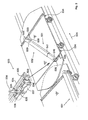
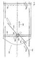
- FIG 1 shows a part of a sorting device 501.
- the sorting device 501 comprises sorting units 502 arranged one behind another, two of which are shown in figure 1 .
- the sorting units 502, which are arranged in an endless train, are each connected to an endless conveyor chain 503, which is driven in the longitudinal direction of the conveyor chain 503 by drive means (not shown). Because of the connection between the conveyor chain 503 and each of the sorting units 502, the sorting units 502 move jointly with the conveyor chain 503 in a conveying direction 504.
- Each sorting unit 502 comprises a carrier plate 505 with a rectangular supporting surface 506 at the upper side thereof for supporting products to be sorted, such as pieces of luggage at airports or packages in distribution centres.
- the carrier plate 505 itself is supported by two wheel arms 507, 508 ( figure 2 ) extending transversely to the conveying direction 504.
- Mounted to the ends of the wheel arms 507, 508 are fixed runners 509, 510.
- the runners 509, 510 run on rails 518.
- the wheel arms 507, 508 are rigidly connected to a link of the conveyor chain 503 in the centre of their length by means of connecting arms 511, 512.
- the wheel arms 507, 508 are provided with connecting plates 513, 514, respectively, in the centre of their length.
- Said connecting plates 513, 514 are provided with a slotted hole 515, which extends in the conveying direction 504, and with a circular hole 516, respectively.
- the carrier plate 505 comprises a downwardly extending connecting pin 517, whose diameter conforms to that of the slotted hole 515 and the circular hole 516.
- the connecting pin 517 associated with a slotted hole 515 extends at the end of the slotted hole 515 remote from the associated circular hole 516.
- the connecting pin 517 in question will move within the slotted hole 515 in the direction of the associated circular hole 516 as a result of the arc-chord effect.
- the wheel arms 507, 508 will rotate about the central axis of the sorting unit 502 associated with the connecting pins 517 with respect to the carrier plate 505 because of the rigid connecting with the conveyor chain 503.
- Each sorting unit 502 furthermore comprises an overlap plate 521, 522 at two opposite ends, which overlap plates are positioned at different vertical levels and which overlap with respective overlap plates 521, 522 of an adjacent sorting unit 502.
- the overlap plates 521, 522 have a convex edge 523, 524 at the ends of the associated sorting unit 502, so that adjacent conveying units 502 will not collide in bends, either.
- the overlap plates 521, 522 of the various conveying units 502 at least largely fill the area between the carrier plates 505 of the various conveying units 502, so that the risk of products landing between the carrier plates 505, which might cause the sorting device to malfunction, is significantly reduced if not ruled out altogether.
- the overlap plates 521, 522 are connected to the associated carrier plate 505 at the longitudinal sides of the sorting device 501, with a certain spacing being present between the overlap plates 521, 522 on the one hand and the carrier plate 505 on the other hand. As a result, a small gap 525, 526 is present between the overlap plates 521, 522 on the one hand and the carrier plate 505 on the other hand.
- each sorting unit 502 also comprises a pusher element 531, which is at least substantially made up of an elongated telescopic pushing member 532 extending the length of the carrier plate 505, at the ends of which a guide assembly 533 is provided.
- Each guide assembly 533 cooperates with a carrier guide 534.
- Two carrier guides 534 are provided for each carrier plate 505, viz. at the front side and at the rear side of the carrier plate 505, seen in the conveying direction 504, on the underside thereof, near the gaps 525, 526.
- the carrier guides 534 extend transversely to the conveying direction 503.
- Each guide assembly 533 is provided with two sliding shoes 535 of plastic material, which engage round a guiding portion of the associated carrier guide 534.
- the sliding shoes 535 form part of a slide block 536 and are mounted to the horizontal part of a corner strip 537.
- the guide assembly 533 further comprises a vertical pivot pin 538, which is attached to the upright part of the corner strip 537. Under the horizontal part of the corner strip 537, two guide wheels 539 being rotatable about their vertical axes are provided side by side, which guide wheels cooperate with guide means yet to be described for moving the guide assembly 533 in question from one longitudinal side to the other longitudinal side of the sorting device 501.
- the guide assemblies 533 associated with a pusher element 531 of a sorting unit 502 are pivotally connected to the pushing member via the respective pivot pins 538.
- the pushing member 532 comprises two pushing member portions 540, 541, of which the pushing member portion 530 can telescope into and out of pushing member portion 541. In this way the length of the pushing member 532 can be adapted to the distance between the associated guide assemblies 533.
- the guide means comprise longitudinal guides 601, 602 extending parallel to the conveying direction 504, which longitudinal guides are provided on opposite longitudinal sides of the sorting device 501.
- the longitudinal guides 601, 602 each consist of a number of longitudinal rails 603 and 604, respectively, arranged in line with each other.
- the facing ends of the longitudinal rails 603 and 604 arranged one behind the other are spaced some distance apart, thus providing passages 605 and 606 between the longitudinal rails 603 and 604, through which guide wheels 539 can pass, as will be elucidated hereinafter.
- the guide means further comprise a sorting guide 608 at the sorting locations 607, which sorting guide is oriented at an angle to the conveying direction 504.
- the sorting guide 608 is provided with an interruption 609, where the connecting arms 511, 512 can pass the sorting guide 608.
- Each sorting guide 608 comprises an upstream guide rail 610 upstream of the interruption 609 and a downstream guide rail 611 downstream of the interruption 609.
- the guide rails 610 and 611 extend in parallel directions, and consequently they are not in line with each other.
- the guide rails 610, 611 are rectilinear in the present preferred embodiment, it is also quite possible within the framework of the present invention for the guide rails 610, 611 to be curvilinear, providing that the guide rails 610, 611 extend in parallel directions at the location of the interruption 609.
- the upstream guide rail 610 has an upstream end 614, which is spaced from the associated longitudinal guide 602 by a distance 615.
- the downstream guide rail 611 has a downstream end 616, which is spaced from the associated longitudinal guide 601 by a distance 617.
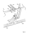
- the guide means are mounted to mounting plates 618, 619 ( figure 5 ).
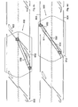
- the guide means further comprise switch means 612 located upstream of each sorting guide 608, which switch means are pivotable about a vertical pivot axis 613 provided on the inner side of the associated longitudinal guide 602, spaced therefrom by some distance, between a passive position as shown in figure 5a and on the left-hand side of figure 4a , and an active position as shown in figure 5b and on the right-hand side of figure 4a . In that passive position shown in figure 5a the switch means 612 abuts against the stop strip 620 with its inner side.
- the sorting means further comprise an auxiliary guide 621 upstream of an associated upstream guide rail 610, which auxiliary guide 621 extends parallel to said upstream guide rail 610 along an upstream part of the length of said upstream guide rail 610.
- the guide means further comprise an auxiliary guide 622 downstream of the downstream guide rail 611, which auxiliary guide 622 extends parallel to said downstream guide rail 611 along part of the length of said downstream guide rail 611.
- the cooperation between the pusher element 531, more specifically the guide assemblies 533 thereof, even more specifically the guide wheels 539 thereof, with the guide means as described above is as follows:
- the starting situation is the situation in which the guide wheels 539 of the two guide assemblies 533 of a pusher element 531 extend on either side of the longitudinal rails 604, and in which consequently the pushing member 532 extends directly above the longitudinal rails 604 in question or directly above the longitudinal guide 602, as is shown in figure 4a .
- the sorting units 502 move in the conveying direction 504.
- the guide assemblies 533 pass the switch means 612.
- the space between the guide wheels 539 associated with a guide assembly 533 is substantially equal to the thickness of the longitudinal rails 604, without ruling out the possibility of some play, for example about 5 mm, being present, so that the guide wheels 539 are guided by opposite side flanks of the longitudinal rails 604.
- the guide assemblies 533, and thus the pusher element 531 in question will continue to follow the longitudinal guide 602. Because of the fact that the upstream end 614 of the upstream guide rail 610 is spaced from the longitudinal guide 602 by a distance 615, sufficient space is available for the inner guide wheel 639a to pass the upstream guide rail 610, in spite of the fact that the guide wheel 539a and the upstream guide rail 610 extend at the same height.
- a guide wheel 539 passes a switch means 612 which is in the active position, as is shown for the right-hand switch means 612 in figure 4a , with the upstream end of the switch means 612 connecting to a downstream end of a respective longitudinal rail 604, the inner guide wheel 539a is deflected inwardly in the direction of the other longitudinal side. During said inward movement, the outer guide wheel 539b passes the opening 606 at the location of the switch means 612 in question. Having passed the active switch means 612, the guide wheel 539a moves further along the auxiliary guide 621.
- the guide wheel 539b Once the outer guide wheel 539b has been moved a distance 615 in the direction of the longitudinal guide 601, said guide wheel 539b will roll against the upstream side of the upstream guide rail 610. Once the guide wheel 539a has completely passed the auxiliary guide 621, the guide assembly 533 is exclusively guided by guiding cooperation between the guide wheel 539b and the upstream guide rail 610, at least up to the interruption 609.
- the guide wheel 539a takes over the guiding function by guiding cooperation with the downstream guide rail 611.
- the thickness of the guide rails 610 and 611 decrease, for example a few mm, at the location of the facing ends of the guide rails 610 and 611, so that the guide wheel 539b will run off the guide rail 610 along gradual lines and the guide wheel 539a will run onto the guide rail 611 along gradual lines.
- This principle may also be used advantageously at other passages in the guide means.
- the guide wheel 539b will roll against the auxiliary guide 622, which, once the guide wheel 539a has passed the downstream end of the downstream guide rail 611, will guide the guide wheels 539 further in the direction of the longitudinal guide 601, in such a manner that the guide wheels 539 will roll against opposite flanks of the longitudinal rail 603. During said movement the guide wheel 539a moves through the passage 605.
- downstream end 616 of the downstream guide rail 611 is spaced from the longitudinal guide 601 by a distance 617, guide wheels 539b associated with a pusher element 531 of a downstream sorting unit 502, which run along the inner side of a longitudinal rail 603, can pass the guide rail 611 without impediment in spite of the fact that the guide wheels 539b are present at the same vertical level as the downstream guide rail 611.
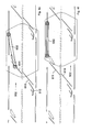
- a front guide assembly 533 ( figures 6-7d ) and a rear guide assembly 533 ( figures 8-9d ) pass an interruption 609 in the sorting guide 608.
- Numerals 651, 652 and 653, 654 in figure 7b and 9b respectively, indicate lines perpendicular to the upstream guide rail 610, which extend through the centre of the two guide wheels 539.
- the associated pivot pins 538 are located outside the area enclosed by the respective lines 651, 652 and 653,654.
Landscapes
- Engineering & Computer Science (AREA)
- Mechanical Engineering (AREA)
- Discharge Of Articles From Conveyors (AREA)
- Branching, Merging, And Special Transfer Between Conveyors (AREA)
Applications Claiming Priority (1)
| Application Number | Priority Date | Filing Date | Title |
|---|---|---|---|
| NL1034156A NL1034156C2 (nl) | 2007-07-18 | 2007-07-18 | Sorteerinrichting. |
Publications (3)
| Publication Number | Publication Date |
|---|---|
| EP2025628A2 true EP2025628A2 (de) | 2009-02-18 |
| EP2025628A3 EP2025628A3 (de) | 2009-03-04 |
| EP2025628B1 EP2025628B1 (de) | 2011-07-06 |
Family
ID=38478137
Family Applications (1)
| Application Number | Title | Priority Date | Filing Date |
|---|---|---|---|
| EP08012917A Not-in-force EP2025628B1 (de) | 2007-07-18 | 2008-07-17 | Sortiereinrichtung |
Country Status (3)
| Country | Link |
|---|---|
| EP (1) | EP2025628B1 (de) |
| AT (1) | ATE515467T1 (de) |
| NL (1) | NL1034156C2 (de) |
Cited By (8)
| Publication number | Priority date | Publication date | Assignee | Title |
|---|---|---|---|---|
| EP2517964A1 (de) * | 2011-04-29 | 2012-10-31 | TriNovate B.V. | Vorrichtung zum Transport und zur gesteuerten Produktabgabe |
| NL2007508C2 (nl) * | 2011-09-30 | 2013-04-02 | Vanderlande Ind Bv | Sorteerinrichting voor het sorteren van producten. |
| CN103949408A (zh) * | 2014-05-09 | 2014-07-30 | 安徽省一一通信息科技有限公司 | 高速货物分拣车及货物分拣系统 |
| WO2016165822A1 (de) * | 2015-04-15 | 2016-10-20 | Interroll Holding Ag | Verbindungsvorrichtung, förderwagen und förderanlage |
| WO2021175389A1 (de) * | 2020-03-06 | 2021-09-10 | Gebhardt Foerdertechnik Gmbh | Förderwagen für einen verteilförderer sowie anbindungsanordnung zur befestigung eines förderwagens an einem antriebsmittel eines verteilförderers |
| WO2022015460A1 (en) * | 2020-07-15 | 2022-01-20 | Laitram, L.L.C. | Self-clearing tray conveyor |
| CN114308689A (zh) * | 2022-02-15 | 2022-04-12 | 中邮科技股份有限公司 | 一种分拣小车及分拣设备 |
| CN117657742A (zh) * | 2023-12-01 | 2024-03-08 | 湖北省烟草公司咸宁市公司 | 一种分拣装置以及烟分拣系统 |
Citations (1)
| Publication number | Priority date | Publication date | Assignee | Title |
|---|---|---|---|---|
| NL9300982A (nl) | 1993-06-08 | 1995-01-02 | Vanderlande Ind Nederland | Transportinrichting. |
Family Cites Families (1)
| Publication number | Priority date | Publication date | Assignee | Title |
|---|---|---|---|---|
| IT1122898B (it) * | 1979-08-30 | 1986-04-30 | Francesco Canziani | Apparecchiatura di selezione e smistamento per oggetti |
-
2007
- 2007-07-18 NL NL1034156A patent/NL1034156C2/nl not_active IP Right Cessation
-
2008
- 2008-07-17 AT AT08012917T patent/ATE515467T1/de not_active IP Right Cessation
- 2008-07-17 EP EP08012917A patent/EP2025628B1/de not_active Not-in-force
Patent Citations (1)
| Publication number | Priority date | Publication date | Assignee | Title |
|---|---|---|---|---|
| NL9300982A (nl) | 1993-06-08 | 1995-01-02 | Vanderlande Ind Nederland | Transportinrichting. |
Cited By (22)
| Publication number | Priority date | Publication date | Assignee | Title |
|---|---|---|---|---|
| EP2682343A1 (de) * | 2011-04-29 | 2014-01-08 | TriNovate B.V. | Vorrichtung zum Transport und zur gesteuerten Produktabgabe |
| WO2012146718A1 (en) * | 2011-04-29 | 2012-11-01 | Trinovate B.V. | An apparatus for transport and controlled discharge of products |
| EP2517964A1 (de) * | 2011-04-29 | 2012-10-31 | TriNovate B.V. | Vorrichtung zum Transport und zur gesteuerten Produktabgabe |
| US9242806B2 (en) | 2011-04-29 | 2016-01-26 | Trinovate B.V. | Apparatus for transport and controlled discharge of products |
| US9540184B2 (en) | 2011-09-30 | 2017-01-10 | Vanderlande Industries B.V. | Sorting device for sorting products |
| CN103958374A (zh) * | 2011-09-30 | 2014-07-30 | 万德兰工业有限公司 | 用于对产品进行分类的分类装置 |
| WO2013048245A1 (en) * | 2011-09-30 | 2013-04-04 | Vanderlande Industries B.V. | Sorting device for sorting products |
| NL2007508C2 (nl) * | 2011-09-30 | 2013-04-02 | Vanderlande Ind Bv | Sorteerinrichting voor het sorteren van producten. |
| CN103958374B (zh) * | 2011-09-30 | 2017-02-22 | 万德兰工业有限公司 | 用于对产品进行分类的分类装置及使用该装置对产品进行分类的方法 |
| CN103949408A (zh) * | 2014-05-09 | 2014-07-30 | 安徽省一一通信息科技有限公司 | 高速货物分拣车及货物分拣系统 |
| CN103949408B (zh) * | 2014-05-09 | 2016-08-17 | 安徽省一一通信息科技有限公司 | 高速货物分拣车及货物分拣系统 |
| WO2016165822A1 (de) * | 2015-04-15 | 2016-10-20 | Interroll Holding Ag | Verbindungsvorrichtung, förderwagen und förderanlage |
| US10099860B2 (en) | 2015-04-15 | 2018-10-16 | Interroll Holding Ag | Connecting device, conveying carriage and conveying installation |
| WO2021175389A1 (de) * | 2020-03-06 | 2021-09-10 | Gebhardt Foerdertechnik Gmbh | Förderwagen für einen verteilförderer sowie anbindungsanordnung zur befestigung eines förderwagens an einem antriebsmittel eines verteilförderers |
| US12103783B2 (en) | 2020-03-06 | 2024-10-01 | Gebhardt Foerdertechnik Gmbh | Conveying carriage for a distributing conveyor and connecting arrangement for fastening a conveying carriage to a drive means of a distributing conveyor |
| WO2022015460A1 (en) * | 2020-07-15 | 2022-01-20 | Laitram, L.L.C. | Self-clearing tray conveyor |
| US20230227264A1 (en) * | 2020-07-15 | 2023-07-20 | Laitram, L.L.C. | Self-clearing tray conveyor |
| US12187543B2 (en) * | 2020-07-15 | 2025-01-07 | Laitram, L.L.C. | Self-clearing tray conveyor |
| CN114308689A (zh) * | 2022-02-15 | 2022-04-12 | 中邮科技股份有限公司 | 一种分拣小车及分拣设备 |
| CN114308689B (zh) * | 2022-02-15 | 2025-11-18 | 中邮科技股份有限公司 | 一种分拣小车及分拣设备 |
| CN117657742A (zh) * | 2023-12-01 | 2024-03-08 | 湖北省烟草公司咸宁市公司 | 一种分拣装置以及烟分拣系统 |
| CN117657742B (zh) * | 2023-12-01 | 2024-06-04 | 湖北省烟草公司咸宁市公司 | 一种分拣装置以及烟分拣系统 |
Also Published As
| Publication number | Publication date |
|---|---|
| EP2025628A3 (de) | 2009-03-04 |
| ATE515467T1 (de) | 2011-07-15 |
| NL1034156C2 (nl) | 2009-01-20 |
| EP2025628B1 (de) | 2011-07-06 |
Similar Documents
| Publication | Publication Date | Title |
|---|---|---|
| EP2025628B1 (de) | Sortiereinrichtung | |
| EP2107993B1 (de) | Sortier-vorrichtung, insbesondere für gepäckstücke | |
| US8770379B2 (en) | Sorting device | |
| EP0782966A1 (de) | Förderer | |
| EP2238057B1 (de) | Sortiervorrichtung, insbesondere für gepäckstücke | |
| EP3693301B1 (de) | Förderer mit schiebern | |
| US20240425300A1 (en) | Cross-belt sorter | |
| EP1826159A1 (de) | Fördersystem | |
| EP0559302B1 (de) | Förderer | |
| EP1828033B1 (de) | Vorrichtung zum gezielten umleiten von produkten zur seite von einer fördereinrichtung | |
| US11400492B2 (en) | Sorting device | |
| NL8302777A (nl) | Transportinrichting voor flessen of dergelijke. | |
| NL1023107C2 (nl) | Continue verticale transporteur met kromme geleidingsbanen. | |
| EP1714920B1 (de) | Kettenförderer |
Legal Events
| Date | Code | Title | Description |
|---|---|---|---|
| PUAI | Public reference made under article 153(3) epc to a published international application that has entered the european phase |
Free format text: ORIGINAL CODE: 0009012 |
|
| PUAL | Search report despatched |
Free format text: ORIGINAL CODE: 0009013 |
|
| AK | Designated contracting states |
Kind code of ref document: A2 Designated state(s): AT BE BG CH CY CZ DE DK EE ES FI FR GB GR HR HU IE IS IT LI LT LU LV MC MT NL NO PL PT RO SE SI SK TR |
|
| AX | Request for extension of the european patent |
Extension state: AL BA MK RS |
|
| AK | Designated contracting states |
Kind code of ref document: A3 Designated state(s): AT BE BG CH CY CZ DE DK EE ES FI FR GB GR HR HU IE IS IT LI LT LU LV MC MT NL NO PL PT RO SE SI SK TR |
|
| AX | Request for extension of the european patent |
Extension state: AL BA MK RS |
|
| 17P | Request for examination filed |
Effective date: 20090804 |
|
| 17Q | First examination report despatched |
Effective date: 20090921 |
|
| AKX | Designation fees paid |
Designated state(s): AT BE BG CH CY CZ DE DK EE ES FI FR GB GR HR HU IE IS IT LI LT LU LV MC MT NL NO PL PT RO SE SI SK TR |
|
| GRAP | Despatch of communication of intention to grant a patent |
Free format text: ORIGINAL CODE: EPIDOSNIGR1 |
|
| GRAS | Grant fee paid |
Free format text: ORIGINAL CODE: EPIDOSNIGR3 |
|
| RAP1 | Party data changed (applicant data changed or rights of an application transferred) |
Owner name: VANDERLANDE INDUSTRIES B.V. |
|
| GRAA | (expected) grant |
Free format text: ORIGINAL CODE: 0009210 |
|
| AK | Designated contracting states |
Kind code of ref document: B1 Designated state(s): AT BE BG CH CY CZ DE DK EE ES FI FR GB GR HR HU IE IS IT LI LT LU LV MC MT NL NO PL PT RO SE SI SK TR |
|
| REG | Reference to a national code |
Ref country code: GB Ref legal event code: FG4D |
|
| REG | Reference to a national code |
Ref country code: CH Ref legal event code: EP |
|
| REG | Reference to a national code |
Ref country code: IE Ref legal event code: FG4D |
|
| REG | Reference to a national code |
Ref country code: DE Ref legal event code: R096 Ref document number: 602008008041 Country of ref document: DE Effective date: 20110825 |
|
| REG | Reference to a national code |
Ref country code: NL Ref legal event code: T3 |
|
| REG | Reference to a national code |
Ref country code: NO Ref legal event code: T2 Effective date: 20110706 |
|
| PG25 | Lapsed in a contracting state [announced via postgrant information from national office to epo] |
Ref country code: SI Free format text: LAPSE BECAUSE OF FAILURE TO SUBMIT A TRANSLATION OF THE DESCRIPTION OR TO PAY THE FEE WITHIN THE PRESCRIBED TIME-LIMIT Effective date: 20110706 |
|
| PG25 | Lapsed in a contracting state [announced via postgrant information from national office to epo] |
Ref country code: MT Free format text: LAPSE BECAUSE OF FAILURE TO SUBMIT A TRANSLATION OF THE DESCRIPTION OR TO PAY THE FEE WITHIN THE PRESCRIBED TIME-LIMIT Effective date: 20110706 |
|
| REG | Reference to a national code |
Ref country code: AT Ref legal event code: MK05 Ref document number: 515467 Country of ref document: AT Kind code of ref document: T Effective date: 20110706 |
|
| PG25 | Lapsed in a contracting state [announced via postgrant information from national office to epo] |
Ref country code: HR Free format text: LAPSE BECAUSE OF FAILURE TO SUBMIT A TRANSLATION OF THE DESCRIPTION OR TO PAY THE FEE WITHIN THE PRESCRIBED TIME-LIMIT Effective date: 20110706 Ref country code: BE Free format text: LAPSE BECAUSE OF FAILURE TO SUBMIT A TRANSLATION OF THE DESCRIPTION OR TO PAY THE FEE WITHIN THE PRESCRIBED TIME-LIMIT Effective date: 20110706 Ref country code: LT Free format text: LAPSE BECAUSE OF FAILURE TO SUBMIT A TRANSLATION OF THE DESCRIPTION OR TO PAY THE FEE WITHIN THE PRESCRIBED TIME-LIMIT Effective date: 20110706 Ref country code: FI Free format text: LAPSE BECAUSE OF FAILURE TO SUBMIT A TRANSLATION OF THE DESCRIPTION OR TO PAY THE FEE WITHIN THE PRESCRIBED TIME-LIMIT Effective date: 20110706 Ref country code: SE Free format text: LAPSE BECAUSE OF FAILURE TO SUBMIT A TRANSLATION OF THE DESCRIPTION OR TO PAY THE FEE WITHIN THE PRESCRIBED TIME-LIMIT Effective date: 20110706 Ref country code: PT Free format text: LAPSE BECAUSE OF FAILURE TO SUBMIT A TRANSLATION OF THE DESCRIPTION OR TO PAY THE FEE WITHIN THE PRESCRIBED TIME-LIMIT Effective date: 20111107 Ref country code: IS Free format text: LAPSE BECAUSE OF FAILURE TO SUBMIT A TRANSLATION OF THE DESCRIPTION OR TO PAY THE FEE WITHIN THE PRESCRIBED TIME-LIMIT Effective date: 20111106 |
|
| PG25 | Lapsed in a contracting state [announced via postgrant information from national office to epo] |
Ref country code: AT Free format text: LAPSE BECAUSE OF FAILURE TO SUBMIT A TRANSLATION OF THE DESCRIPTION OR TO PAY THE FEE WITHIN THE PRESCRIBED TIME-LIMIT Effective date: 20110706 Ref country code: CY Free format text: LAPSE BECAUSE OF FAILURE TO SUBMIT A TRANSLATION OF THE DESCRIPTION OR TO PAY THE FEE WITHIN THE PRESCRIBED TIME-LIMIT Effective date: 20110706 Ref country code: GR Free format text: LAPSE BECAUSE OF FAILURE TO SUBMIT A TRANSLATION OF THE DESCRIPTION OR TO PAY THE FEE WITHIN THE PRESCRIBED TIME-LIMIT Effective date: 20111007 Ref country code: PL Free format text: LAPSE BECAUSE OF FAILURE TO SUBMIT A TRANSLATION OF THE DESCRIPTION OR TO PAY THE FEE WITHIN THE PRESCRIBED TIME-LIMIT Effective date: 20110706 Ref country code: MC Free format text: LAPSE BECAUSE OF NON-PAYMENT OF DUE FEES Effective date: 20110731 Ref country code: LV Free format text: LAPSE BECAUSE OF FAILURE TO SUBMIT A TRANSLATION OF THE DESCRIPTION OR TO PAY THE FEE WITHIN THE PRESCRIBED TIME-LIMIT Effective date: 20110706 |
|
| REG | Reference to a national code |
Ref country code: IE Ref legal event code: MM4A |
|
| PG25 | Lapsed in a contracting state [announced via postgrant information from national office to epo] |
Ref country code: SK Free format text: LAPSE BECAUSE OF FAILURE TO SUBMIT A TRANSLATION OF THE DESCRIPTION OR TO PAY THE FEE WITHIN THE PRESCRIBED TIME-LIMIT Effective date: 20110706 Ref country code: CZ Free format text: LAPSE BECAUSE OF FAILURE TO SUBMIT A TRANSLATION OF THE DESCRIPTION OR TO PAY THE FEE WITHIN THE PRESCRIBED TIME-LIMIT Effective date: 20110706 |
|
| PLBE | No opposition filed within time limit |
Free format text: ORIGINAL CODE: 0009261 |
|
| STAA | Information on the status of an ep patent application or granted ep patent |
Free format text: STATUS: NO OPPOSITION FILED WITHIN TIME LIMIT |
|
| PG25 | Lapsed in a contracting state [announced via postgrant information from national office to epo] |
Ref country code: EE Free format text: LAPSE BECAUSE OF FAILURE TO SUBMIT A TRANSLATION OF THE DESCRIPTION OR TO PAY THE FEE WITHIN THE PRESCRIBED TIME-LIMIT Effective date: 20110706 Ref country code: RO Free format text: LAPSE BECAUSE OF FAILURE TO SUBMIT A TRANSLATION OF THE DESCRIPTION OR TO PAY THE FEE WITHIN THE PRESCRIBED TIME-LIMIT Effective date: 20110706 Ref country code: IT Free format text: LAPSE BECAUSE OF FAILURE TO SUBMIT A TRANSLATION OF THE DESCRIPTION OR TO PAY THE FEE WITHIN THE PRESCRIBED TIME-LIMIT Effective date: 20110706 |
|
| 26N | No opposition filed |
Effective date: 20120411 |
|
| PG25 | Lapsed in a contracting state [announced via postgrant information from national office to epo] |
Ref country code: DK Free format text: LAPSE BECAUSE OF FAILURE TO SUBMIT A TRANSLATION OF THE DESCRIPTION OR TO PAY THE FEE WITHIN THE PRESCRIBED TIME-LIMIT Effective date: 20110706 |
|
| PG25 | Lapsed in a contracting state [announced via postgrant information from national office to epo] |
Ref country code: IE Free format text: LAPSE BECAUSE OF NON-PAYMENT OF DUE FEES Effective date: 20110717 |
|
| REG | Reference to a national code |
Ref country code: DE Ref legal event code: R097 Ref document number: 602008008041 Country of ref document: DE Effective date: 20120411 |
|
| REG | Reference to a national code |
Ref country code: CH Ref legal event code: PL |
|
| PG25 | Lapsed in a contracting state [announced via postgrant information from national office to epo] |
Ref country code: CH Free format text: LAPSE BECAUSE OF NON-PAYMENT OF DUE FEES Effective date: 20120731 Ref country code: LI Free format text: LAPSE BECAUSE OF NON-PAYMENT OF DUE FEES Effective date: 20120731 Ref country code: ES Free format text: LAPSE BECAUSE OF FAILURE TO SUBMIT A TRANSLATION OF THE DESCRIPTION OR TO PAY THE FEE WITHIN THE PRESCRIBED TIME-LIMIT Effective date: 20111017 |
|
| PG25 | Lapsed in a contracting state [announced via postgrant information from national office to epo] |
Ref country code: LU Free format text: LAPSE BECAUSE OF NON-PAYMENT OF DUE FEES Effective date: 20110717 |
|
| PG25 | Lapsed in a contracting state [announced via postgrant information from national office to epo] |
Ref country code: BG Free format text: LAPSE BECAUSE OF FAILURE TO SUBMIT A TRANSLATION OF THE DESCRIPTION OR TO PAY THE FEE WITHIN THE PRESCRIBED TIME-LIMIT Effective date: 20111006 |
|
| PG25 | Lapsed in a contracting state [announced via postgrant information from national office to epo] |
Ref country code: TR Free format text: LAPSE BECAUSE OF FAILURE TO SUBMIT A TRANSLATION OF THE DESCRIPTION OR TO PAY THE FEE WITHIN THE PRESCRIBED TIME-LIMIT Effective date: 20110706 |
|
| PG25 | Lapsed in a contracting state [announced via postgrant information from national office to epo] |
Ref country code: HU Free format text: LAPSE BECAUSE OF FAILURE TO SUBMIT A TRANSLATION OF THE DESCRIPTION OR TO PAY THE FEE WITHIN THE PRESCRIBED TIME-LIMIT Effective date: 20110706 |
|
| REG | Reference to a national code |
Ref country code: FR Ref legal event code: PLFP Year of fee payment: 8 |
|
| REG | Reference to a national code |
Ref country code: FR Ref legal event code: PLFP Year of fee payment: 9 |
|
| PGFP | Annual fee paid to national office [announced via postgrant information from national office to epo] |
Ref country code: GB Payment date: 20160721 Year of fee payment: 9 Ref country code: DE Payment date: 20160722 Year of fee payment: 9 Ref country code: NO Payment date: 20160725 Year of fee payment: 9 |
|
| PGFP | Annual fee paid to national office [announced via postgrant information from national office to epo] |
Ref country code: FR Payment date: 20160721 Year of fee payment: 9 |
|
| REG | Reference to a national code |
Ref country code: DE Ref legal event code: R119 Ref document number: 602008008041 Country of ref document: DE |
|
| REG | Reference to a national code |
Ref country code: NO Ref legal event code: MMEP |
|
| GBPC | Gb: european patent ceased through non-payment of renewal fee |
Effective date: 20170717 |
|
| REG | Reference to a national code |
Ref country code: FR Ref legal event code: ST Effective date: 20180330 |
|
| PG25 | Lapsed in a contracting state [announced via postgrant information from national office to epo] |
Ref country code: DE Free format text: LAPSE BECAUSE OF NON-PAYMENT OF DUE FEES Effective date: 20180201 Ref country code: NO Free format text: LAPSE BECAUSE OF NON-PAYMENT OF DUE FEES Effective date: 20170731 Ref country code: GB Free format text: LAPSE BECAUSE OF NON-PAYMENT OF DUE FEES Effective date: 20170717 |
|
| PG25 | Lapsed in a contracting state [announced via postgrant information from national office to epo] |
Ref country code: FR Free format text: LAPSE BECAUSE OF NON-PAYMENT OF DUE FEES Effective date: 20170731 |
|
| PGFP | Annual fee paid to national office [announced via postgrant information from national office to epo] |
Ref country code: NL Payment date: 20190719 Year of fee payment: 12 |
|
| REG | Reference to a national code |
Ref country code: NL Ref legal event code: MM Effective date: 20200801 |
|
| PG25 | Lapsed in a contracting state [announced via postgrant information from national office to epo] |
Ref country code: NL Free format text: LAPSE BECAUSE OF NON-PAYMENT OF DUE FEES Effective date: 20200801 |