EP2025636A2 - Dispositif de levage pour unités de cellulose - Google Patents
Dispositif de levage pour unités de cellulose Download PDFInfo
- Publication number
- EP2025636A2 EP2025636A2 EP08396012A EP08396012A EP2025636A2 EP 2025636 A2 EP2025636 A2 EP 2025636A2 EP 08396012 A EP08396012 A EP 08396012A EP 08396012 A EP08396012 A EP 08396012A EP 2025636 A2 EP2025636 A2 EP 2025636A2
- Authority
- EP
- European Patent Office
- Prior art keywords
- claw
- boxes
- lifting device
- horizontal
- balk
- Prior art date
- Legal status (The legal status is an assumption and is not a legal conclusion. Google has not performed a legal analysis and makes no representation as to the accuracy of the status listed.)
- Withdrawn
Links
- 229920002678 cellulose Polymers 0.000 title 1
- 239000001913 cellulose Substances 0.000 title 1
- 210000000078 claw Anatomy 0.000 claims abstract description 63
- 238000000926 separation method Methods 0.000 claims description 2
- 230000004888 barrier function Effects 0.000 description 2
- 238000000034 method Methods 0.000 description 2
- MKYBYDHXWVHEJW-UHFFFAOYSA-N N-[1-oxo-1-(2,4,6,7-tetrahydrotriazolo[4,5-c]pyridin-5-yl)propan-2-yl]-2-[[3-(trifluoromethoxy)phenyl]methylamino]pyrimidine-5-carboxamide Chemical compound O=C(C(C)NC(=O)C=1C=NC(=NC=1)NCC1=CC(=CC=C1)OC(F)(F)F)N1CC2=C(CC1)NN=N2 MKYBYDHXWVHEJW-UHFFFAOYSA-N 0.000 description 1
- 238000012432 intermediate storage Methods 0.000 description 1
- 239000000463 material Substances 0.000 description 1
- 239000003351 stiffener Substances 0.000 description 1
Images


Classifications
-
- B—PERFORMING OPERATIONS; TRANSPORTING
- B66—HOISTING; LIFTING; HAULING
- B66C—CRANES; LOAD-ENGAGING ELEMENTS OR DEVICES FOR CRANES, CAPSTANS, WINCHES, OR TACKLES
- B66C1/00—Load-engaging elements or devices attached to lifting or lowering gear of cranes or adapted for connection therewith for transmitting lifting forces to articles or groups of articles
- B66C1/10—Load-engaging elements or devices attached to lifting or lowering gear of cranes or adapted for connection therewith for transmitting lifting forces to articles or groups of articles by mechanical means
- B66C1/42—Gripping members engaging only the external or internal surfaces of the articles
- B66C1/44—Gripping members engaging only the external or internal surfaces of the articles and applying frictional forces
- B66C1/445—Gripping members engaging only the external or internal surfaces of the articles and applying frictional forces motor actuated
- B66C1/447—Gripping members engaging only the external or internal surfaces of the articles and applying frictional forces motor actuated by hydraulic or pneumatic motors
-
- B—PERFORMING OPERATIONS; TRANSPORTING
- B66—HOISTING; LIFTING; HAULING
- B66C—CRANES; LOAD-ENGAGING ELEMENTS OR DEVICES FOR CRANES, CAPSTANS, WINCHES, OR TACKLES
- B66C1/00—Load-engaging elements or devices attached to lifting or lowering gear of cranes or adapted for connection therewith for transmitting lifting forces to articles or groups of articles
- B66C1/10—Load-engaging elements or devices attached to lifting or lowering gear of cranes or adapted for connection therewith for transmitting lifting forces to articles or groups of articles by mechanical means
- B66C1/22—Rigid members, e.g. L-shaped members, with parts engaging the under surface of the loads; Crane hooks
- B66C1/28—Duplicate, e.g. pivoted, members engaging the loads from two sides
- B66C1/30—Duplicate, e.g. pivoted, members engaging the loads from two sides and also arranged to grip the sides of the loads
- B66C1/32—Duplicate, e.g. pivoted, members engaging the loads from two sides and also arranged to grip the sides of the loads of piled or stacked articles
Definitions
- the aim of the invention is a lifting device for goods, like pulp units which are bound with a binding device to which lifting device is belonging at least one horizontal balk which is attached to a crane and to which horizontal balk several claw boxes which are moveable in a direction of the mentioned balk are attached in which case each claw box is designed to grip the binding device for an item to be lifted which is located near to it while gripping elements which belong to the boxes are brought closer to each other while a binding element stays to be supported by the gripping elements.
- the pulp units are packages which have the shape of a rectangle in which packages the pulp is transported from a factory to usage targets.
- the size of the pulp units may vary but they usually weigh about 2,000 kg.
- the upper surface of the units is usually flat.
- the unit contains several bales and is bound to stay together with the help of a binding element, such a wire which is wound around the unit.
- pulp units are loaded and transferred at harbours or similar locations from a transport vehicle or a intermediate storage to the cargo hold of a ship or the other way round by using harbour crane and a special lifting device attached to it.
- the lifting device has several (for example 1 - 4) claw boxes and the aim is that several pulp units can be transferred with the lifting device at one go.
- the pulp units are transferred in such a way that the lifting device is transferred above the pulp unit and it is put down downwards in such a way that the claw boxes touch the binding rims for the pulp units in such a way that the claws which act as gripping elements are located to the opposite sides of the lifting rims.
- the material of the pulp unit gets squeezed a little and when the claws are transferred to be at the opposite sides of each other, they go under the lifting rims. After that the pulp units can be lifted upwards while being supported by the lifting rims and they can be transported to a cargo hold of a ship or to another desired location.
- a lifting device for pulp units according to the introduction of the claim 1 is known.
- the claw boxes have a structure which prevents wobbling of the load when they are put down onto the load while the lift is being prepared.
- the claw boxes When the claw boxes are supported by chains or cables or similar things, the claw boxes may sometimes flutter uncontrollable in relation to the main balks and especially when they are being transferred while they are empty from one place to another.
- the modem lifting devices With the help of the modem lifting devices a group of four units can advantageously be lifted and transferred to a ship. Problems occur when the lifts of the most groups are being performed. In the hold of the ship the unit groups should be arranged close to each other and at the dock while being brought out of the hold, a gap which is at least 100 mm should be arranged between the groups for transferring a group which is performed by a forklift truck. The whole group can be transferred by a forklift truck if it has been separated to a distance of at least 100 mm from another group.
- the aim of the invention is to present a lifting device for pulp units with the help of which several disadvantages related to the current lifting devices can be removed.
- the aim of the invention is especially to present a lifting device for pulp units with the help of which pulp unit groups can be both lifted and these groups can be arranged close to each other and also a needed amount of groups can be separated from each other.
- each horizontal balk comprises claw boxes separated according to the sizes of the units being supported by the balk.
- the claw boxes can be moved at least according to the unit groups in which case two or more unit groups can be arranged both to a row without gaps and the groups can be arranged in such a way that there is a little distance between them.
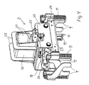
- each horizontal balk 1 comprises claw boxes 2 which are arranged with a separation determined by the size of the unit and located on the horizontal balk.
- End plates 6 belong to the outermost claw boxes 2a, 2b the position of which can advantageously be adjusted according to the size of the unit sideways in relation to the claw boxes 2a, 2b. End plates 6 are located lower than the lower part of the claw boxes 2.
- Two side control units 5 are attached to the horizontal balk 1 the aim of which is to stop the swinging movement of the lifting device and to position the device on top of the unit groups which are formed of the units 7.
- the transfer bar 20 is in two parts in such a way that its parts are integrated in the middle with a hydraulic cylinder 4. With the help of the cylinder 4 the left and right parts of the transfer bar can be brought closer towards each other and brought further away from each other.
- groups which are formed of four claw boxes are moveable towards each other and away from each other with the help of the cylinder 4 according to the figure 1 .
- the end plates which belong to the outermost claw boxes 2a, 2b have several tasks. Firstly the wobbling of the whole lifting device can be stopped by putting the lifting device down to the ground for a moment to be supported by the end plates 6. Further two or more unit groups can be compressed to be one unit row by putting down the horizontal balk 1 onto the unit row in which case the unit row becomes squeezed to be shorter with the help of the end plates. Before that the transfer bar 20 is driven to its longest position with the help of a cylinder 4 and when the cylinder 4 is squeezed, it is driven shorter. In this way two or more bale groups can be arranged to be one long group and they can be transferred to the ship without the groups having a distance x between them which is about 100 - 200 mm.
- binding element 8 around the units 7 and by gripping it with the gripping elements of the claw boxes the unit can be arranged to be lifted.
- claw boxes 2 which are attached to the horizontal balk 1 are shown to which claw boxes two pairs of gripping claws 10 belong while the pairs are a distance apart from each other. Further the claws 10 are a distance apart from each other and can be brought closer to each other in which case they take the binding element between them from the surface of the unit onto the claws while they have been put down onto the unit.
- FIG 2 also the attachment of the side control unit 5 to the horizontal balk 1 is shown. With the help of a sliding casing 3 which is supported by the horizontal balk.
- the side control unit is attached to a transfer bar 20 which goes underneath the horizontal balk 1 in which case it moves sideways like the claw boxes while the transfer bar 20 is being moved.
- FIG 3 the adjustment of the position in relation to the distance of the side guide unit 5 with the help of a telescopically implemented attachment way by moving the shaft 12 in a tube 16 and by locking the shaft to the tube through the holes 15 for example with taps.
- the side guide unit 5 can be put down with the help of the cylinder 13 and telescopic slide bar attachments 14 in order to get support from the unit row and it is not an uplifted barrier when the unit load is put down next to the other unit row completely close to it.
- the guide unit 5 is attached with the help of a hinge 29 to the shaft 12 so that it can turn in which case it possibly turns and withdraws while it is being put down and when it touches an barrier due to its design.
- the side guide unit assembly becomes attached to a structure 3 which slides supported by the horizontal balk 1 and also on the other hand to the transfer bar 20 through the brackets 17 ( Figure 2 ).
- FIG 5 the structure of the gripping elements 10, 19 is shown in more detail. While a claw box 2 is being put down onto a unit 7, each gripping element 19 can separately withdraw upwards against the spring 11 and its own weight. With this procedure the functioning of the gripping elements 10, 19 on an uneven unit surface can be ensured and the functioning especially in big unit rows in which there are for example 8 - 12 units in a row and one horizontal balk with its claw box is put down onto them in which case also in that case the claw 10 which is located at the lower end of each gripping element 19 should be on the surface of the unit.
- the binding elements 8 of the units between the gripping elements 10, 19 are on the surface of the units.
- the gripping elements 10, 19 are moved towards each other so that they almost touch each other in which case at least the claw parts 10 will be overlapping.
- the horizontal balks 24, which can be moved inside the tubes 23, belong to the shafts 19 of the gripping elements and thus the distance of the gripping element pairs on the surface of the bale can be adjusted, if needed.
- the locking of the adjustment is made either with a bolt or with a locking where a tap is put into a hole.
- the pulling of the shafts 19 close to each other and the fact that the binding device will be supported by the claws 10 is made with the help of a hydraulic cylinder which is inside the body 27 of the claw box.
- the horizontal tubes 23 which are located on both sides of the structure are pulled in such a way that they almost touch each other.
- the gripping element arrangement becomes thus narrower in its entirety inside the body 27 supported by two horizontal axes 18 when the tags 26 slide towards each other on top of the mentioned axes.
- the tags 26 are attached to the horizontal tubes 23.
- Intentionally formed shafts of the plates 9 are located near the gripping shafts 19 them being attached to the upper end of the shafts 19 with the help of a hinge. Free turning of them downwards, more than in the figure 5, is limited with the help of stoppers. Instead of that they can withdraw upwards by turning around their fastening point.
- the task of these shafts of the plate 9 is to ensure that the binding element 8 comes loose from the claws 10 almost immediately when the shafts 19 and the claws 10 are being separated from each other. With this procedure it is ensured that the binding element stays approximately in the middle of the unit in order to make the next possible lift easier.
- the claw box 2 is attached to the transfer bar 20 through the holders 22.
- the holders 22 and the transfer bar 20 have several optional holes in which case the mutual distance between the claw boxes can be adjusted according to the size of the unit.
Landscapes
- Engineering & Computer Science (AREA)
- Mechanical Engineering (AREA)
- Load-Engaging Elements For Cranes (AREA)
Applications Claiming Priority (1)
| Application Number | Priority Date | Filing Date | Title |
|---|---|---|---|
| FI20070591A FI120031B (fi) | 2007-08-07 | 2007-08-07 | Selluyksiköiden nostolaite |
Publications (2)
| Publication Number | Publication Date |
|---|---|
| EP2025636A2 true EP2025636A2 (fr) | 2009-02-18 |
| EP2025636A3 EP2025636A3 (fr) | 2012-04-18 |
Family
ID=38468661
Family Applications (1)
| Application Number | Title | Priority Date | Filing Date |
|---|---|---|---|
| EP08396012A Withdrawn EP2025636A3 (fr) | 2007-08-07 | 2008-08-06 | Dispositif de levage pour unités de cellulose |
Country Status (2)
| Country | Link |
|---|---|
| EP (1) | EP2025636A3 (fr) |
| FI (1) | FI120031B (fr) |
Cited By (4)
| Publication number | Priority date | Publication date | Assignee | Title |
|---|---|---|---|---|
| WO2016066899A1 (fr) * | 2014-10-29 | 2016-05-06 | Stevenel Oy | Appareil de levage d'articles liés entre eux par un moyen de cerclage |
| CN110228751A (zh) * | 2019-07-16 | 2019-09-13 | 哈尔滨工程机械制造有限责任公司 | 一种纸浆包的自动吊装和码垛装置 |
| WO2021170911A1 (fr) * | 2020-02-24 | 2021-09-02 | Stevenel Oy | Dispositif de levage pour unités de pâte |
| WO2025066995A1 (fr) * | 2023-09-25 | 2025-04-03 | 青岛港国际股份有限公司 | Fixation de serrage pour palettisation de marchandises empaquetées dans un entreposage |
Families Citing this family (1)
| Publication number | Priority date | Publication date | Assignee | Title |
|---|---|---|---|---|
| ES2610033B1 (es) * | 2015-09-22 | 2018-01-30 | Biele, S.A. | Dispositivo de apilado automatizado universal |
Citations (1)
| Publication number | Priority date | Publication date | Assignee | Title |
|---|---|---|---|---|
| US3587889A (en) | 1968-06-11 | 1971-06-28 | Svenska Cellulosa Ab | Method and apparatus for handling a load |
Family Cites Families (2)
| Publication number | Priority date | Publication date | Assignee | Title |
|---|---|---|---|---|
| US3700274A (en) * | 1971-03-04 | 1972-10-24 | Forrest Paschal Machinery Co | Apparatus for stacking uncured brick |
| FI117132B (fi) * | 2002-05-21 | 2006-06-30 | Stevenel Oy | Sellupaalien nostolaite |
-
2007
- 2007-08-07 FI FI20070591A patent/FI120031B/fi not_active IP Right Cessation
-
2008
- 2008-08-06 EP EP08396012A patent/EP2025636A3/fr not_active Withdrawn
Patent Citations (1)
| Publication number | Priority date | Publication date | Assignee | Title |
|---|---|---|---|---|
| US3587889A (en) | 1968-06-11 | 1971-06-28 | Svenska Cellulosa Ab | Method and apparatus for handling a load |
Cited By (7)
| Publication number | Priority date | Publication date | Assignee | Title |
|---|---|---|---|---|
| WO2016066899A1 (fr) * | 2014-10-29 | 2016-05-06 | Stevenel Oy | Appareil de levage d'articles liés entre eux par un moyen de cerclage |
| CN107148394A (zh) * | 2014-10-29 | 2017-09-08 | 斯蒂维内尔股份有限公司 | 用于提升通过捆扎装置捆绑在一起的物品的装置 |
| CN107148394B (zh) * | 2014-10-29 | 2018-06-15 | 斯蒂维内尔股份有限公司 | 用于提升通过捆扎装置捆绑在一起的物品的装置 |
| CN110228751A (zh) * | 2019-07-16 | 2019-09-13 | 哈尔滨工程机械制造有限责任公司 | 一种纸浆包的自动吊装和码垛装置 |
| WO2021170911A1 (fr) * | 2020-02-24 | 2021-09-02 | Stevenel Oy | Dispositif de levage pour unités de pâte |
| CN115667117A (zh) * | 2020-02-24 | 2023-01-31 | 斯蒂维内尔股份有限公司 | 用于纸浆单元的提升装置 |
| WO2025066995A1 (fr) * | 2023-09-25 | 2025-04-03 | 青岛港国际股份有限公司 | Fixation de serrage pour palettisation de marchandises empaquetées dans un entreposage |
Also Published As
| Publication number | Publication date |
|---|---|
| EP2025636A3 (fr) | 2012-04-18 |
| FI120031B (fi) | 2009-06-15 |
| FI20070591A0 (fi) | 2007-08-07 |
| FI20070591L (fi) | 2009-02-08 |
Similar Documents
| Publication | Publication Date | Title |
|---|---|---|
| US9376236B2 (en) | Container including object-supporting chute and pivot mechanism | |
| EP2025636A2 (fr) | Dispositif de levage pour unités de cellulose | |
| EP0904248B1 (fr) | Cadre de levage et procede d'utilisation associe | |
| CN110446678B (zh) | 提升运输集装箱 | |
| EP2354054B1 (fr) | Station de chargement et de déchargement | |
| KR101679929B1 (ko) | 하중 전환장치를 포함하는 강판 이송 전자석 리프터 및 이를 이용한 강판 이송 방법 | |
| CN102625753A (zh) | 货物运载器 | |
| KR20120003917U (ko) | 케이블 드럼 이송 장치 | |
| EP1033342A2 (fr) | Pince de levage pour transporter des bobines de bande métallique | |
| EP3212558B1 (fr) | Appareil de levage d'articles liés entre eux par un moyen de cerclage | |
| US20200002137A1 (en) | Apparatus and method for carrying elongate construction elements | |
| EP2818044A1 (fr) | Système et procédé pour manipuler des volailles vivantes | |
| EP3228581B1 (fr) | Panier amélioré pour plate-forme aérienne de celui-ci | |
| FI127072B (fi) | Haalauspalkki, sen nostojärjestely ja kuljetin | |
| US5775753A (en) | Equipment for loading containers | |
| US12434954B2 (en) | Lifting attachment for lifting containers | |
| EP3208175A1 (fr) | Transpalette avec système side-chargement retractable | |
| EP2042369A1 (fr) | Appareil de transport | |
| EP2346774B1 (fr) | Appareil, système et procédé de manipulation de pièces allongées | |
| EP1603823B1 (fr) | Repartiteur de levage lateral pour conteneur | |
| EP0558152B1 (fr) | Conteneur pour le transport de produits tels que des tubes | |
| EP1012076B1 (fr) | Systeme de stockage | |
| EP1806312A2 (fr) | Dispositif et procede pour le levage de charges | |
| KR102558894B1 (ko) | 화물 이동 장비 | |
| US5730253A (en) | Robotic shelf handling apparatus |
Legal Events
| Date | Code | Title | Description |
|---|---|---|---|
| PUAI | Public reference made under article 153(3) epc to a published international application that has entered the european phase |
Free format text: ORIGINAL CODE: 0009012 |
|
| AK | Designated contracting states |
Kind code of ref document: A2 Designated state(s): AT BE BG CH CY CZ DE DK EE ES FI FR GB GR HR HU IE IS IT LI LT LU LV MC MT NL NO PL PT RO SE SI SK TR |
|
| AX | Request for extension of the european patent |
Extension state: AL BA MK RS |
|
| PUAL | Search report despatched |
Free format text: ORIGINAL CODE: 0009013 |
|
| AK | Designated contracting states |
Kind code of ref document: A3 Designated state(s): AT BE BG CH CY CZ DE DK EE ES FI FR GB GR HR HU IE IS IT LI LT LU LV MC MT NL NO PL PT RO SE SI SK TR |
|
| AX | Request for extension of the european patent |
Extension state: AL BA MK RS |
|
| RIC1 | Information provided on ipc code assigned before grant |
Ipc: B66C 1/44 20060101ALI20120314BHEP Ipc: B66C 1/28 20060101AFI20120314BHEP |
|
| AKY | No designation fees paid | ||
| REG | Reference to a national code |
Ref country code: DE Ref legal event code: R108 |
|
| REG | Reference to a national code |
Ref country code: DE Ref legal event code: R108 Effective date: 20130102 |
|
| 17P | Request for examination filed |
Effective date: 20121026 |
|
| RBV | Designated contracting states (corrected) |
Designated state(s): AT BE BG CH CY CZ DE DK EE ES FI FR GB GR HR HU IE IS IT LI LT LU LV MC MT NL NO PL PT RO SE SI SK TR |
|
| 17Q | First examination report despatched |
Effective date: 20130220 |
|
| GRAP | Despatch of communication of intention to grant a patent |
Free format text: ORIGINAL CODE: EPIDOSNIGR1 |
|
| INTG | Intention to grant announced |
Effective date: 20140707 |
|
| STAA | Information on the status of an ep patent application or granted ep patent |
Free format text: STATUS: THE APPLICATION IS DEEMED TO BE WITHDRAWN |
|
| 18D | Application deemed to be withdrawn |
Effective date: 20141118 |