EP2025831A2 - Transportsystem für Flügelglätter - Google Patents
Transportsystem für Flügelglätter Download PDFInfo
- Publication number
- EP2025831A2 EP2025831A2 EP08014459A EP08014459A EP2025831A2 EP 2025831 A2 EP2025831 A2 EP 2025831A2 EP 08014459 A EP08014459 A EP 08014459A EP 08014459 A EP08014459 A EP 08014459A EP 2025831 A2 EP2025831 A2 EP 2025831A2
- Authority
- EP
- European Patent Office
- Prior art keywords
- trowel
- wheels
- transport system
- frame
- blades
- Prior art date
- Legal status (The legal status is an assumption and is not a legal conclusion. Google has not performed a legal analysis and makes no representation as to the accuracy of the status listed.)
- Withdrawn
Links
- 238000000034 method Methods 0.000 claims description 8
- 239000000463 material Substances 0.000 claims description 6
- 230000005484 gravity Effects 0.000 claims description 5
- 230000007246 mechanism Effects 0.000 claims description 2
- 230000000712 assembly Effects 0.000 description 35
- 238000000429 assembly Methods 0.000 description 35
- 239000011295 pitch Substances 0.000 description 12
- NJPPVKZQTLUDBO-UHFFFAOYSA-N novaluron Chemical compound C1=C(Cl)C(OC(F)(F)C(OC(F)(F)F)F)=CC=C1NC(=O)NC(=O)C1=C(F)C=CC=C1F NJPPVKZQTLUDBO-UHFFFAOYSA-N 0.000 description 5
- 238000012986 modification Methods 0.000 description 4
- 230000004048 modification Effects 0.000 description 4
- 238000013519 translation Methods 0.000 description 3
- 230000014616 translation Effects 0.000 description 3
- 230000009286 beneficial effect Effects 0.000 description 2
- 238000010276 construction Methods 0.000 description 2
- 230000001627 detrimental effect Effects 0.000 description 2
- 238000009499 grossing Methods 0.000 description 2
- 230000013011 mating Effects 0.000 description 2
- 230000000153 supplemental effect Effects 0.000 description 2
- 230000002411 adverse Effects 0.000 description 1
- 230000008859 change Effects 0.000 description 1
- 238000002485 combustion reaction Methods 0.000 description 1
- 230000000694 effects Effects 0.000 description 1
- 230000003028 elevating effect Effects 0.000 description 1
- 238000007730 finishing process Methods 0.000 description 1
- 239000002828 fuel tank Substances 0.000 description 1
- 238000009434 installation Methods 0.000 description 1
- 238000012423 maintenance Methods 0.000 description 1
- 230000004044 response Effects 0.000 description 1
- XLYOFNOQVPJJNP-UHFFFAOYSA-N water Substances O XLYOFNOQVPJJNP-UHFFFAOYSA-N 0.000 description 1
Images


Classifications
-
- E—FIXED CONSTRUCTIONS
- E04—BUILDING
- E04F—FINISHING WORK ON BUILDINGS, e.g. STAIRS, FLOORS
- E04F21/00—Implements for finishing work on buildings
- E04F21/20—Implements for finishing work on buildings for laying flooring
- E04F21/24—Implements for finishing work on buildings for laying flooring of masses made in situ, e.g. smoothing tools
- E04F21/245—Rotary power trowels, i.e. helicopter trowels
- E04F21/247—Rotary power trowels, i.e. helicopter trowels used by an operator sitting on the trowel, i.e. ride-on power trowels
Definitions
- the concrete is allowed to cure for another 15 minutes to one-half hour, and the machine is operated at progressively increasing speeds and progressively increasing blade pitches up to the performance of a finishing or "burning" operation at the highest possible speed--preferably above about 150 rpm and up to about 200 rpm.
- the riding trowel is supported by the engagement between the number of blades and the underlying concrete material.
- the weight of the machine assists the finishing process.
- the weight of the machine can be beneficial for providing efficient, robust, and powerful trowel operation, the weight of the machine is also detrimental to non-use transportation of the trowel, i.e. while moving the trowel to or from a worksite without operating the blades.
- supplemental equipment such as a skid loader, a backhoe, or the like, is utilized to move the machine to and from a work surface.
- Some concrete finishing trowels are fitted with lift points for attachment to a chain for this purpose.
- two or more laborers are required to manually lift and move the machine. This is a labor some and physically demanding means of moving such machines.
- Previous trowel transport systems have been disclosed which include a number of retractable wheels or casters that are securable to the frame of the trowel.
- One such system is a removable wheel kit or dolly disclosed in U.S. Patent 5,238,323 to Allen et al.
- the wheel kit disclosed in the Allen '323 patent includes a pair of wheel assemblies secured to generally opposite sides of the exterior of the cage of a riding trowel.
- a separate jack is provided for each wheel assembly so that each jack independently raises and lowers a separate wheel assembly relative to the frame.
- the wheels support the trowel such that a single user can move the entire trowel by simply pushing or pulling it in an intended direction.
- the wheel assemblies disclosed in the '323 patent being positioned outside a normal footprint of the machine, are exposed to the obstacles, such as walls, posts, or the like, and thus increase an offset between an outer edge of the machine and an outer edge of the area finished by the blades.
- the areas that cannot be finished due to the interference between the wheel assemblies and the obstructions must be finished by hand, increasing the amount of hand work associated with a given pour. This problem can be avoided only by removing the wheel assemblies prior to commencing a finishing operation.
- a transport system for a concrete finishing trowel that requires less effort than previously-known transport systems to be converted between a stowed position and a deployed operational position.
- an easily deployed concrete finishing trowel transport system that does not unnecessarily increase the footprint of the machine. It is further desired to provide a trowel transport system that can be implemented into a number of machine configurations as well as one that is relatively simple to operate, inexpensive to produce, and simple to maintain.
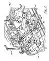
- the pedestal 40 is positioned generally longitudinally centrally on deck 38 at a rear portion thereof and supports operator's seat 34.
- a fuel tank 44 is disposed adjacent the left side of pedestal 40, and a water retardant tank 46 is disposed on the right side of pedestal 40.
- a lift cage assembly 48 is attached to the upper surface of the deck 38 beneath pedestal 40 and seat 34. Lift cage assembly 48 is used to transport power trowel 20 when supplemental equipment is available and/or for those application when manual movement of power trowel 20 is impractical, such as pours commonly associated with tall structures or loading of the machine onto raised flatbed vehicles.
- each rotor assembly 24, 26 includes a gearbox 58, a driven shaft 60 extending downwardly from the gearbox, and a plurality of circumferentially-spaced blades 62 supported on the driven shaft 60 via radial support arms 64 and extending radially outwardly from the bottom end of the driven shaft 60 so as to rest on the concrete surface.
- Each gearbox 58 is mounted on the undersurface of the deck 38 so as to be tiltable relative to deck 38 and frame 36 for reasons detailed below.
- a thrust collar (not shown) cooperates with a yoke 78 that is movable to force the thrust collar into a position pivoting trowel blades 62 about an axis extending perpendicular to the axis of the driven shaft 60.
- a tension cable 81 extends from the crank 74, through the post 72, and to the yoke 78 to interconnect the yoke 78 with the crank 74. Rotation of the crank 74 adjusts the yoke's angle to move the thrust collar 76 up or down thereby providing a desired degree of trowel blade pitch adjustment.
- the pitch of blades 62 is often varied as the material being finished sets and becomes more resistant to being worked by the blades.
- a power concrete finishing trowel having this type of blade pitch adjustment assembly is disclosed, e.g., in U.S. Pat. No. 2,887,934 to Whiteman , the disclosure of which is hereby incorporated by reference.
- At least one of handles 28, 30 is constructed to be movable in the fore and aft directions as well as side-to-side directions.
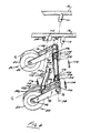
- a lift device in the form of a jack 102 extends through the rear of cage 32 and is operatively connected to shaft 84.
- Jack 102 includes a telescoping tube assembly including a first or outer tube 118 fixed to the frame 36 and a second or inner tube 120.
- the outer tube 118 is bolted to the frame 36 via flange 110 that extends from outer tube 118.
- a pin 116 extends through an opening 112 in the flange 110 and into a mating opening 113 in a bracket 114 extending from frame 36. Pin 116 fixes a position of the outer tube 118 of jack 102 relative to frame 36.
- jack arm 106 and shaft 84 rotates jack arm 106 and shaft 84 about axis 94.
- Rotation of shaft 84 about axis 94 translates wheel assemblies 80, 82 from the stowed orientation shown in solid lines in Fig. 2 to the deployed or operational orientation shown in phantom lines in Fig. 2 in which the wheels 83 support machine 20.
- both wheel assemblies 80 and 82 are rotated by a common shaft 84, the wheel assemblies 80 and 82 are raised and lowered an equal amount by operation of a single jack 102.
- the operation of a single jack to effectuate a balanced change in elevation of machine 20 allows an operator to quickly and efficiently prepare the machine 20 for moving it from one job to another. Operation of the jack in the operation manner retracts the wheel assembly back to their stowed position shown in solid lines in Fig. 2 , whereupon the machine 20 rests on the blades 62.
- the inventive system reduces operator effort to configure the riding trowel for non-assisted transportation, provides an efficient means of changing the elevation of the machine and does not adversely affect the footprint of the trowel.
Landscapes
- Engineering & Computer Science (AREA)
- Architecture (AREA)
- Civil Engineering (AREA)
- Structural Engineering (AREA)
- Road Paving Machines (AREA)
- On-Site Construction Work That Accompanies The Preparation And Application Of Concrete (AREA)
- Handcart (AREA)
Applications Claiming Priority (1)
| Application Number | Priority Date | Filing Date | Title |
|---|---|---|---|
| US11/839,967 US7771139B2 (en) | 2007-08-16 | 2007-08-16 | Concrete trowel transport system |
Publications (2)
| Publication Number | Publication Date |
|---|---|
| EP2025831A2 true EP2025831A2 (de) | 2009-02-18 |
| EP2025831A3 EP2025831A3 (de) | 2012-08-08 |
Family
ID=39884793
Family Applications (1)
| Application Number | Title | Priority Date | Filing Date |
|---|---|---|---|
| EP08014459A Withdrawn EP2025831A3 (de) | 2007-08-16 | 2008-08-13 | Transportsystem für Flügelglätter |
Country Status (7)
| Country | Link |
|---|---|
| US (1) | US7771139B2 (de) |
| EP (1) | EP2025831A3 (de) |
| JP (1) | JP5561919B2 (de) |
| CN (1) | CN101372867B (de) |
| AU (1) | AU2008203808B2 (de) |
| BR (1) | BRPI0804448A2 (de) |
| CA (1) | CA2638631C (de) |
Cited By (1)
| Publication number | Priority date | Publication date | Assignee | Title |
|---|---|---|---|---|
| RU2589776C2 (ru) * | 2011-04-05 | 2016-07-10 | Ломар С.Р.Л | Бетоноотделочная машина для выравнивания оснований пола |
Families Citing this family (11)
| Publication number | Priority date | Publication date | Assignee | Title |
|---|---|---|---|---|
| USD615561S1 (en) * | 2009-01-29 | 2010-05-11 | Larry Jake Chapple | Mid section for ride-on machine |
| US8414219B2 (en) | 2010-12-22 | 2013-04-09 | Wacker Neuson Production Americas Llc | Concrete trowel transport system |
| CN103422660B (zh) * | 2013-07-31 | 2016-09-21 | 周尔康 | 地坪刮涂机机头 |
| US10370863B2 (en) | 2016-08-24 | 2019-08-06 | Wagman Metal Products Inc. | Offset mounting adapter for concrete surface processing tool |
| CA3019606C (en) * | 2016-12-20 | 2019-07-02 | 2544-9455 Quebec Inc. | Powered concrete finishing apparatus having annular working surface |
| CN110185245B (zh) * | 2019-06-28 | 2021-04-06 | 广东博智林机器人有限公司 | 抹平机构 |
| US11585049B2 (en) * | 2019-08-28 | 2023-02-21 | Caterpillar Paving Products Inc. | Overload support system for a paving machine screed assembly |
| CN110565925B (zh) * | 2019-09-11 | 2021-03-19 | 广东博智林机器人有限公司 | 抹平机器人 |
| CN114960360A (zh) * | 2022-07-08 | 2022-08-30 | 民航机场建设工程有限公司 | 一种机场道面抹平拉毛设备 |
| CN115506211B (zh) * | 2022-09-21 | 2024-11-08 | 山东正顺建设集团有限公司 | 一种混凝土找平提浆装置及其使用方法 |
| CN119062115B (zh) * | 2024-10-30 | 2025-03-07 | 苏州创凡达机械股份有限公司 | 抹平机 |
Citations (2)
| Publication number | Priority date | Publication date | Assignee | Title |
|---|---|---|---|---|
| US2887934A (en) | 1956-04-06 | 1959-05-26 | Marvin E Whiteman | Cement finishing machine |
| US5238323A (en) | 1990-07-13 | 1993-08-24 | Allen Engineering Corporation | Riding trowel for concrete finishing |
Family Cites Families (25)
| Publication number | Priority date | Publication date | Assignee | Title |
|---|---|---|---|---|
| US2621568A (en) | 1946-09-23 | 1952-12-16 | Horace G Fletcher | Concrete troweling machine and attachment therefor |
| US2983203A (en) | 1954-11-04 | 1961-05-09 | Horace G Fletcher | Troweling machine |
| US2898826A (en) | 1956-04-23 | 1959-08-11 | Frank W Livermont | Paving machine |
| BE630582A (de) * | 1962-04-06 | 1963-07-31 | ||
| US3303524A (en) * | 1965-01-27 | 1967-02-14 | Walter E Schneider | Vertically adjustable cradle for a surface brushing machine |
| US3778078A (en) * | 1972-06-05 | 1973-12-11 | T Onder | Wheel assembly device |
| US3877830A (en) * | 1973-08-27 | 1975-04-15 | Renner Co | Towed paver with thickness and leveling control |
| US3901616A (en) * | 1974-07-22 | 1975-08-26 | Kenneth J Greening | Self-propelled paver |
| US4113403A (en) * | 1977-08-31 | 1978-09-12 | Stone Construction Equipment Inc. | Plate type compactor |
| WO1986004633A1 (fr) * | 1985-02-04 | 1986-08-14 | Kabushiki Kaisha Takenaka Komuten | Machine de finition de plancher en beton |
| US4710055A (en) | 1986-07-02 | 1987-12-01 | M-B-W Inc. | Riding-type multiple trowel machine |
| US4978132A (en) * | 1989-09-14 | 1990-12-18 | Wilson P Henry | Pivotable hand truck apparatus |
| US5088799A (en) | 1990-07-09 | 1992-02-18 | Redmon Gerald W | Attachment wheels for concrete finishing machines |
| USD340340S (en) | 1991-10-18 | 1993-10-12 | Allen Engineering Corporation | Riding trowel cranking dolly wheel assembly |
| US5288166A (en) * | 1992-06-26 | 1994-02-22 | Allen Engineering Corporation | Laser operated automatic grade control system for concrete finishing |
| EP0763410B1 (de) * | 1995-09-15 | 2003-04-23 | Von Arx Ag | Fahrbares Oberflächenbearbeitungsgerät |
| DE29815362U1 (de) * | 1998-08-27 | 1998-12-10 | Pesek, Gerold, 69256 Mauer | Transportvorrichtung für schwere Gegenstände |
| US6059299A (en) | 1999-06-14 | 2000-05-09 | Rust; Loval M. | Machine for transporting equipment |
| US6347907B1 (en) * | 2000-01-06 | 2002-02-19 | David Halstead | Dolly and method of use |
| USD465897S1 (en) | 2001-07-19 | 2002-11-19 | Allen Engineering Corp. | Power trowel dolly |
| USD518070S1 (en) * | 2003-10-13 | 2006-03-28 | Wacker Construction Equipment Ag | Vibrating plate |
| US7204657B2 (en) * | 2004-03-22 | 2007-04-17 | Gerald Mclain Jackson | Lightweight self-leveling automatic screed apparatus |
| CN2725419Y (zh) * | 2004-07-23 | 2005-09-14 | 周德平 | 混凝土面层压实抹光机 |
| CN100451273C (zh) * | 2007-02-09 | 2009-01-14 | 张旭东 | 地面修平机 |
| CN201133069Y (zh) * | 2007-12-06 | 2008-10-15 | 上海杰工建筑机械有限公司 | 一种水泥抹光机 |
-
2007
- 2007-08-16 US US11/839,967 patent/US7771139B2/en active Active
-
2008
- 2008-08-11 AU AU2008203808A patent/AU2008203808B2/en not_active Ceased
- 2008-08-12 BR BRPI0804448-1A patent/BRPI0804448A2/pt not_active IP Right Cessation
- 2008-08-12 CA CA2638631A patent/CA2638631C/en active Active
- 2008-08-13 EP EP08014459A patent/EP2025831A3/de not_active Withdrawn
- 2008-08-15 JP JP2008209172A patent/JP5561919B2/ja not_active Expired - Fee Related
- 2008-08-18 CN CN200810212408XA patent/CN101372867B/zh not_active Expired - Fee Related
Patent Citations (2)
| Publication number | Priority date | Publication date | Assignee | Title |
|---|---|---|---|---|
| US2887934A (en) | 1956-04-06 | 1959-05-26 | Marvin E Whiteman | Cement finishing machine |
| US5238323A (en) | 1990-07-13 | 1993-08-24 | Allen Engineering Corporation | Riding trowel for concrete finishing |
Cited By (1)
| Publication number | Priority date | Publication date | Assignee | Title |
|---|---|---|---|---|
| RU2589776C2 (ru) * | 2011-04-05 | 2016-07-10 | Ломар С.Р.Л | Бетоноотделочная машина для выравнивания оснований пола |
Also Published As
| Publication number | Publication date |
|---|---|
| CA2638631A1 (en) | 2009-02-16 |
| AU2008203808B2 (en) | 2014-06-05 |
| US20090047070A1 (en) | 2009-02-19 |
| CA2638631C (en) | 2015-08-11 |
| CN101372867B (zh) | 2012-11-07 |
| BRPI0804448A2 (pt) | 2010-01-05 |
| AU2008203808A1 (en) | 2009-03-05 |
| CN101372867A (zh) | 2009-02-25 |
| JP5561919B2 (ja) | 2014-07-30 |
| JP2009046975A (ja) | 2009-03-05 |
| EP2025831A3 (de) | 2012-08-08 |
| US7771139B2 (en) | 2010-08-10 |
Similar Documents
| Publication | Publication Date | Title |
|---|---|---|
| US7771139B2 (en) | Concrete trowel transport system | |
| US5238323A (en) | Riding trowel for concrete finishing | |
| EP2271804B1 (de) | Vorrichtung zur endbearbeitung von beton | |
| US5480258A (en) | Variable width, twin engine riding trowel | |
| US7775740B2 (en) | Concrete trowel steering system | |
| US8414219B2 (en) | Concrete trowel transport system | |
| JP3953261B2 (ja) | コンクリート仕上げトロエル及びその操縦方法 | |
| US4710055A (en) | Riding-type multiple trowel machine | |
| US5470131A (en) | Methods and apparatus for cutting circular slots in pavement extending about manhole castings | |
| EP1516962A2 (de) | Mehrzweckdeckenfertiger mit Zusatzgeräten | |
| US6350083B1 (en) | Powered roller screed | |
| US7108451B2 (en) | Rotating concrete finishing trowel | |
| US20080193264A1 (en) | Wheel lift system | |
| HK1130858A (en) | Concrete trowel transport system | |
| WO2006009532A1 (en) | High lift truck | |
| EP0713551A4 (de) | Vorrichtung zum nahtlosen verlegen von bodenbelag | |
| JP2020105718A (ja) | 除雪機 | |
| HK1128742A (en) | Concrete trowel steering system | |
| WO2008093131A1 (en) | A machine for excavating |
Legal Events
| Date | Code | Title | Description |
|---|---|---|---|
| PUAI | Public reference made under article 153(3) epc to a published international application that has entered the european phase |
Free format text: ORIGINAL CODE: 0009012 |
|
| AK | Designated contracting states |
Kind code of ref document: A2 Designated state(s): AT BE BG CH CY CZ DE DK EE ES FI FR GB GR HR HU IE IS IT LI LT LU LV MC MT NL NO PL PT RO SE SI SK TR |
|
| AX | Request for extension of the european patent |
Extension state: AL BA MK RS |
|
| RIN1 | Information on inventor provided before grant (corrected) |
Inventor name: GRAHL, SCOTT |
|
| REG | Reference to a national code |
Ref country code: HK Ref legal event code: DE Ref document number: 1130858 Country of ref document: HK |
|
| RAP1 | Party data changed (applicant data changed or rights of an application transferred) |
Owner name: WACKER NEUSON CORPORATION |
|
| REG | Reference to a national code |
Ref country code: DE Ref legal event code: R108 Effective date: 20110503 |
|
| RAP1 | Party data changed (applicant data changed or rights of an application transferred) |
Owner name: WACKER NEUSON PRODUCTION AMERICAS LLC |
|
| PUAL | Search report despatched |
Free format text: ORIGINAL CODE: 0009013 |
|
| AK | Designated contracting states |
Kind code of ref document: A3 Designated state(s): AT BE BG CH CY CZ DE DK EE ES FI FR GB GR HR HU IE IS IT LI LT LU LV MC MT NL NO PL PT RO SE SI SK TR |
|
| AX | Request for extension of the european patent |
Extension state: AL BA MK RS |
|
| RIC1 | Information provided on ipc code assigned before grant |
Ipc: E04F 21/24 20060101AFI20120702BHEP |
|
| 17P | Request for examination filed |
Effective date: 20130206 |
|
| AKX | Designation fees paid |
Designated state(s): AT BE BG CH CY CZ DE DK EE ES FI FR GB GR HR HU IE IS IT LI LT LU LV MC MT NL NO PL PT RO SE SI SK TR |
|
| STAA | Information on the status of an ep patent application or granted ep patent |
Free format text: STATUS: THE APPLICATION HAS BEEN WITHDRAWN |
|
| 18W | Application withdrawn |
Effective date: 20140711 |
|
| REG | Reference to a national code |
Ref country code: HK Ref legal event code: WD Ref document number: 1130858 Country of ref document: HK |