EP2025875B1 - Turbinendichtung und Sicherungsdichtung von einem Gasturbinentriebwerk - Google Patents
Turbinendichtung und Sicherungsdichtung von einem Gasturbinentriebwerk Download PDFInfo
- Publication number
- EP2025875B1 EP2025875B1 EP08252699.7A EP08252699A EP2025875B1 EP 2025875 B1 EP2025875 B1 EP 2025875B1 EP 08252699 A EP08252699 A EP 08252699A EP 2025875 B1 EP2025875 B1 EP 2025875B1
- Authority
- EP
- European Patent Office
- Prior art keywords
- seal
- assembly
- face
- runner
- gas turbine
- Prior art date
- Legal status (The legal status is an assumption and is not a legal conclusion. Google has not performed a legal analysis and makes no representation as to the accuracy of the status listed.)
- Active
Links
Images


Classifications
-
- F—MECHANICAL ENGINEERING; LIGHTING; HEATING; WEAPONS; BLASTING
- F16—ENGINEERING ELEMENTS AND UNITS; GENERAL MEASURES FOR PRODUCING AND MAINTAINING EFFECTIVE FUNCTIONING OF MACHINES OR INSTALLATIONS; THERMAL INSULATION IN GENERAL
- F16J—PISTONS; CYLINDERS; SEALINGS
- F16J15/00—Sealings
- F16J15/002—Sealings comprising at least two sealings in succession
- F16J15/008—Sealings comprising at least two sealings in succession with provision to put out of action at least one sealing; One sealing sealing only on standstill; Emergency or servicing sealings
-
- F—MECHANICAL ENGINEERING; LIGHTING; HEATING; WEAPONS; BLASTING
- F01—MACHINES OR ENGINES IN GENERAL; ENGINE PLANTS IN GENERAL; STEAM ENGINES
- F01D—NON-POSITIVE DISPLACEMENT MACHINES OR ENGINES, e.g. STEAM TURBINES
- F01D11/00—Preventing or minimising internal leakage of working-fluid, e.g. between stages
- F01D11/02—Preventing or minimising internal leakage of working-fluid, e.g. between stages by non-contact sealings, e.g. of labyrinth type
- F01D11/04—Preventing or minimising internal leakage of working-fluid, e.g. between stages by non-contact sealings, e.g. of labyrinth type using sealing fluid, e.g. steam
-
- F—MECHANICAL ENGINEERING; LIGHTING; HEATING; WEAPONS; BLASTING
- F02—COMBUSTION ENGINES; HOT-GAS OR COMBUSTION-PRODUCT ENGINE PLANTS
- F02C—GAS-TURBINE PLANTS; AIR INTAKES FOR JET-PROPULSION PLANTS; CONTROLLING FUEL SUPPLY IN AIR-BREATHING JET-PROPULSION PLANTS
- F02C7/00—Features, components parts, details or accessories, not provided for in, or of interest apart form groups F02C1/00 - F02C6/00; Air intakes for jet-propulsion plants
- F02C7/28—Arrangement of seals
-
- F—MECHANICAL ENGINEERING; LIGHTING; HEATING; WEAPONS; BLASTING
- F16—ENGINEERING ELEMENTS AND UNITS; GENERAL MEASURES FOR PRODUCING AND MAINTAINING EFFECTIVE FUNCTIONING OF MACHINES OR INSTALLATIONS; THERMAL INSULATION IN GENERAL
- F16J—PISTONS; CYLINDERS; SEALINGS
- F16J15/00—Sealings
- F16J15/16—Sealings between relatively-moving surfaces
- F16J15/34—Sealings between relatively-moving surfaces with slip-ring pressed against a more or less radial face on one member
- F16J15/3404—Sealings between relatively-moving surfaces with slip-ring pressed against a more or less radial face on one member and characterised by parts or details relating to lubrication, cooling or venting of the seal
- F16J15/3408—Sealings between relatively-moving surfaces with slip-ring pressed against a more or less radial face on one member and characterised by parts or details relating to lubrication, cooling or venting of the seal at least one ring having an uneven slipping surface
- F16J15/3412—Sealings between relatively-moving surfaces with slip-ring pressed against a more or less radial face on one member and characterised by parts or details relating to lubrication, cooling or venting of the seal at least one ring having an uneven slipping surface with cavities
- F16J15/342—Sealings between relatively-moving surfaces with slip-ring pressed against a more or less radial face on one member and characterised by parts or details relating to lubrication, cooling or venting of the seal at least one ring having an uneven slipping surface with cavities with means for feeding fluid directly to the face
-
- F—MECHANICAL ENGINEERING; LIGHTING; HEATING; WEAPONS; BLASTING
- F05—INDEXING SCHEMES RELATING TO ENGINES OR PUMPS IN VARIOUS SUBCLASSES OF CLASSES F01-F04
- F05D—INDEXING SCHEME FOR ASPECTS RELATING TO NON-POSITIVE-DISPLACEMENT MACHINES OR ENGINES, GAS-TURBINES OR JET-PROPULSION PLANTS
- F05D2240/00—Components
- F05D2240/55—Seals
-
- F—MECHANICAL ENGINEERING; LIGHTING; HEATING; WEAPONS; BLASTING
- F05—INDEXING SCHEMES RELATING TO ENGINES OR PUMPS IN VARIOUS SUBCLASSES OF CLASSES F01-F04
- F05D—INDEXING SCHEME FOR ASPECTS RELATING TO NON-POSITIVE-DISPLACEMENT MACHINES OR ENGINES, GAS-TURBINES OR JET-PROPULSION PLANTS
- F05D2300/00—Materials; Properties thereof
- F05D2300/20—Oxide or non-oxide ceramics
- F05D2300/22—Non-oxide ceramics
- F05D2300/224—Carbon, e.g. graphite
Definitions
- the disclosure generally relates to gas turbine engines.
- a gas turbine engine typically maintains pressure differentials between various components during operation. These pressure differentials are commonly maintained by various configurations of seals. Exemplary sealing arrangements for gas turbine engines are described in EP 1348898 A1 , US 4,103,899 , US 2,545,916 , GB 1,174,207 , US 5,975,537 and US 5,284,347 . US 2,545,916 , which shows the technical features of the preamble of independent claim 1, discloses labyrinth packing for use in internal combustion turbines.
- Labyrinth seals oftentimes are used in gas turbine engines. As is known, labyrinth seals tend to deteriorate over time. By way of example, a labyrinth seal can deteriorate due to rub interactions from thermal and mechanical growths, assembly tolerances, engine loads and maneuver deflections. Unfortunately, such deterioration can cause increased flow consumption resulting in increased parasitic losses and thermodynamic cycle loss.
- the present invention provides a seal assembly for a gas turbine engine comprising: a hydrostatic seal having a seal face and a seal runner, wherein the seal face is a portion of a seal face assembly having a mounting bracket, the mounting bracket being operative to removably mount the seal face assembly within the gas turbine engine, and wherein the seal runner is a portion of a seal runner assembly having a mounting bracket, the mounting bracket being operative to removably mount the seal runner assembly within the gas turbine engine; and a back-up seal, wherein the back-up seal is a labyrinth seal having a land and a knife edge, the knife edge being operative to interact with the land to form a seal; wherein the land is supported by an arm that is attached to the mounting bracket of the seal face assembly and the knife edge is supported by an arm that is attached to the mounting bracket of the seal runner assembly; and wherein, in a normal mode of operation of the hydrostatic seal, interaction of the seal face and the seal runner maintains a pressure differential within the
- hydrostatic face seals can be used at various locations of a gas turbine engine, such as in association with a low-pressure turbine.
- a hydrostatic seal is a seal that uses balanced opening and closing forces to maintain a desired separation between a seal face and a corresponding seal runner.
- use of such a seal can be problematic, particularly when carbon is used to form the seal face.
- pressure fluctuations and/or vibrations could cause undesired contact between the seal face and a corresponding seal runner that can cause damage to the seal, e.g., carbon fracture.
- a back-up seal can be provided.
- FIG. 1 is a schematic diagram depicting an exemplary embodiment of a gas turbine engine.
- engine 100 is configured as a turbofan that incorporates a fan 102, a compressor section 104, a combustion section 106 and a turbine section 108.
- FIG. 1 is configured as a turbofan, there is no intention to limit the concepts described herein to use with turbofans, as various other configurations of gas turbine engines can be used.
- Engine 100 is a dual spool engine that includes a high-pressure turbine 110 interconnected with a high-pressure compressor 112 via a shaft 114, and a low-pressure turbine 120 interconnected with a low-pressure compressor 122 via a shaft 124. Note that the low-pressure turbine 120 will be described in greater detail later with respect to FIGS. 4 and 5 . It should also be noted that although various embodiments are described as incorporating hydrostatic face seals in low-pressure turbines, such seals are not limited only to use with low-pressure turbines.
- FIG. 2 schematically depicts an embodiment of a low-pressure turbine that incorporates a primary hydrostatic face seal without a back-up seal installed.
- low-pressure turbine 220 defines a primary gas flow path 230 along which multiple rotating blades (e.g., blade 232) and stationary vanes (e.g., vane 234) are located.
- the blades are mounted to turbine disks, the respective webs and bores of which extend into a high-pressure cavity 240.
- disk 242 includes a web 244 and a bore 246, each of which extends into cavity 240.
- a relatively lower-pressure cavity 248 is oriented between high-pressure cavity 240 and turbine hub 249, with a hydrostatic seal 250 being provided to maintain a pressure differential between the high-pressure cavity and the lower-pressure cavity. Note that the arrows depict representative locations at which the higher-pressure gas attempts to leak from the high-pressure cavity.
- Hydrostatic seal 250 is configured as a lift-off seal incorporating a seal face 252 and a seal runner 254.
- the seal face intermittently contacts the seal runner.
- contact between the seal face and the seal runner can occur during sub-idle conditions and/or during transient conditions. However, during normal operating conditions, the seal face and the seal runner should not contact each other.
- the seal face is positioned by a carrier 256 that can translate axially with respect to the seal runner.
- a spring 258 is biased to urge the carrier so that the seal face contacts the seal runner. In operation, contact between the seal face and the seal runner is maintained until gas pressure in the high-pressure cavity is adequate to overcome the biasing force, thereby separating the seal face from the seal runner.
- FIG. 2 Since the embodiment of FIG. 2 is configured as a lift-off seal (i.e., at least intermittent contact is expected), materials forming the surfaces that will contact each other are selected, at least in part, for their durability.
- a material comprising carbon can be used as a seal face material. It should be noted, however, that carbon can fracture or otherwise be damaged due to unwanted contact (e.g., excessively forceful contact) between the seal face and the seal runner as may be caused by unintended pressure fluctuations and/or vibrations, for example. Unfortunately, such damage may result in failure of the primary seal as depicted schematically in FIG. 3 .
- FIG. 3 an unintended failure of the seal face is depicted.
- the seal face is no longer capable of adequately maintaining a pressure differential between the high pressure cavity 240 and the lower pressure cavity 248.
- a seal face may no longer be capable of adequately maintaining a pressure differential based on one or more other conditions, such as a stuck-open failure.
- a stuck-open failure can occur, for example, due to a faulty biasing spring and/or a jammed carrier.
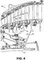
- FIGS. 4 and 5 schematically depict an exemplary embodiment of a low-pressure turbine that incorporates a hydrostatic face seal with a back-up seal according to an embodiment of the present invention.
- low-pressure turbine 120 is associated with engine 100 of FIG. 1 .
- low-pressure turbine 120 defines a primary gas flow path 130 along which multiple rotating blades (e.g., blade 132) and stationary vanes (e.g., vane 134) are located.
- the blades are mounted to turbine disks, the respective webs and bores of which extend into a high-pressure cavity 140.
- disk 142 includes a web 144 and a bore 146, each of which extends into cavity 140.
- a relatively lower-pressure cavity 148 is oriented between high-pressure cavity 140 and turbine hub 149, with a hydrostatic seal 150 being provided to maintain a pressure differential between the high-pressure cavity and the lower-pressure cavity.
- An intermediate pressure cavity 151 is oriented between high-pressure cavity 140 and lower-pressure cavity 148. Note that the arrows depict representative locations at which the higher-pressure gas attempts to leak from the high-pressure cavity into flow path 130.
- hydrostatic seal 150 is configured as a lift-off seal incorporating a seal face 152 and a seal runner 154.
- the seal face forms a portion of a seal face assembly 153, which also includes a mounting bracket 155 for removably mounting the assembly.
- Seal runner 154 is provided as a portion of a seal runner assembly 160 that includes a mounting bracket 162.
- seal 150 is provided as a removable assembly, the location of which can be adjusted axially and radially.
- providing a hydrostatic face seal as an adjustable and/or removable assembly can enable thrust balance trimming of the gas turbine engine in which the hydrostatic face seal is installed.
- the seal face intermittently contacts the seal runner.
- contact between the seal face and the seal runner can occur during sub-idle conditions and/or during transient conditions.
- the seal face and the seal runner should not contact each other.
- the seal face is positioned by a carrier 166 that can translate axially with respect to mounting bracket 155, which is attached to a non-rotating component of the engine.
- a biasing member 168 e.g., a spring
- a biasing member 168 is biased to urge the carrier so that the seal face contacts the seal runner. In operation, contact between the seal face and the seal runner is maintained until gas pressure in the high-pressure cavity is adequate to overcome the biasing force, thereby separating the seal face from the seal runner.
- FIGS. 1 , 4 and 5 Since the embodiment of FIGS. 1 , 4 and 5 is configured as a lift-off seal (i.e., at least intermittent contact is expected), materials forming the surfaces that will contact each other are selected, at least in part, for their durability.
- a material comprising carbon can be used as a seal face material. It should be noted, however, that carbon may be susceptible to deterioration at higher temperatures. Therefore, carbon should be used in locations where predicted temperatures are not excessive. By way of example, use of such a material may not be appropriate, in some embodiments, in a high-pressure turbine.
- a back-up seal 170 is also shown in FIG. 5.
- the back-up seal is a labyrinth seal, although various other types of seals such as brush seals, for example, could be used in other embodiments.
- Back-up seal 170 in this embodiment is configured as a two-step seal, with each step incorporating an abradable seal land such as honeycomb, for example.
- the lands 172, 174 are supported by an arm 176 that is attached to mounting bracket 155.
- the lands of the labyrinth seal are provided as a portion of the seal face assembly.
- the steps can be provided as a separate assembly or can be supported by another component, such as a seal runner assembly.
- Steps 172, 174 are engaged by corresponding knife edges 182, 184, which are supported by an arm 186.
- the knife edges 182, 184 operate in close proximity to the lands 172, 174. This interaction provides a leakage restriction, thus creating a seal.
- Arm 186 is attached to mounting bracket 162.
- the knife edges of the labyrinth seal are provided as a portion of the seal runner assembly 160.
- the knife edges can be provided as a separate assembly or can be supported by another component, such as a seal face assembly.
- a nominal pressure differential exists between intermediate pressure cavity 151 and lower-pressure cavity 148. That is, the pressure differential between cavities 140 and 148 is maintained, at least primarily, across the hydrostatic seal 150.
- a failure mode of operation i.e., the hydrostatic seal deteriorates or fails
- the pressure of the high-pressure cavity 140 is depleted to a level lower than during the normal mode of operation but higher than that of intermediate cavity 151 during normal operation.
- the increase in pressure differential across the back-up seal 170 is due to the increased flow rate imposed on the back-up seal during failure of the primary seal.
- pressure in intermediate cavity 151 increases and a corresponding pressure differential is maintained, at least primarily, across the back-up seal 170.
Landscapes
- Engineering & Computer Science (AREA)
- General Engineering & Computer Science (AREA)
- Mechanical Engineering (AREA)
- Chemical & Material Sciences (AREA)
- Combustion & Propulsion (AREA)
- Turbine Rotor Nozzle Sealing (AREA)
- Sealing Using Fluids, Sealing Without Contact, And Removal Of Oil (AREA)
Claims (8)
- Dichtungsanordnung für ein Gasturbinentriebwerk umfassend:eine Dichtung (150) mit einer Dichtungsfläche (152) und einem Dichtungsläufer (154),wobei die Dichtungsfläche (152) ein Teil einer Dichtungsflächenanordnung (153) ist, die einen Anbringungshalter (155) aufweist, wobei der Anbringungshalter (155) dazu in der Lage ist, die Dichtungsflächenanordnung (153) entfernbar innerhalb des Gasturbinentriebwerks anzubringen, und wobei der Dichtungsläufer (154) ein Teil einer Dichtungsläuferanordnung (160) ist, die einen Anbringungshalter (162) aufweist, der dazu in der Lage ist, die Dichtungsläuferanordnung (160) entfernbar innerhalb des Gasturbinentriebwerks anzubringen; undeine Sicherungsdichtung (170), wobei es sich bei der Sicherungsdichtung (170) um eine Labyrinthdichtung handelt, die einen Steg (172) und eine Messerkante (182) aufweist, wobei die Messerkante (182) dazu in der Lage ist, mit dem Steg (172) zusammenzuwirken, um eine Dichtung zu bilden;wobei der Steg (172) durch einen Arm (176) gestützt ist, der am Anbringungshalter (155) der Dichtungsflächenanordnung (153) angebracht ist und die Messerkante (182) durch einen Arm (186) gestützt ist, der am Anbringungshalter (162) der Dichtungsläuferanordnung (160) angebracht ist; undwobei in einem normalen Betriebszustand der Dichtung (150) das Zusammenwirken der Dichtungsfläche (152) und des Dichtungsläufers (154) eine Druckdifferenz innerhalb des Gasturbinentriebwerks aufrechterhält, und in einem fehlerhaften Betriebszustand der Dichtung (150) die Sicherungsdichtung (170) eine Druckdifferenz innerhalb des Gasturbinentriebwerks aufrechterhält, gekennzeichnet dadurch, dass es sich bei der Dichtung (150) um eine hydrostatische Dichtung, die als eine Abhebedichtung ausgebildet ist, handelt.
- Anordnung nach Anspruch 1, wobei die hydrostatische Dichtung (150) eine Abhebedichtung ist, wobei die Dichtungsfläche (152) zu einer Kontaktposition hin beaufschlagt ist, in welcher die Dichtungsfläche (152) den Dichtungsläufer (154) kontaktiert.
- Anordnung nach Anspruch 2, wobei die Dichtungsflächenanordnung (153) ein Beaufschlagungselement (168) aufweist, das betriebsfähig ist, um die Dichtungsfläche (152) zu der Kontaktposition hin zu beaufschlagen.
- Anordnung nach einem der vorangehenden Ansprüche, wobei zumindest ein Teil der Dichtungsfläche (152), die so ausgebildet ist, dass sie den Dichtungsläufer (154) kontaktiert, aus einem Material, das Karbon umfasst, ausgebildet ist.
- Turbinenanordnung für ein Gasturbinentriebwerk umfassend:eine Turbine mit einer Dichtungsanordnung nach Anspruch 1.
- Anordnung nach Anspruch 5, wobei zumindest ein Teil der Dichtungsfläche (152), die so ausgebildet ist, dass sie den Dichtungsläufer (154) kontaktiert, aus einem Material, das Karbon umfasst, ausgebildet ist.
- Anordnung nach Anspruch 5 oder 6, wobei die Turbine eine Niederdruckturbine ist.
- Anordnung nach einem der Ansprüche 5 bis 7, wobei die hydrostatische Dichtung (150) eine Abhebedichtung ist, wobei die Dichtungsfläche (152) zu einer Kontaktposition hin beaufschlagt ist, in welcher die Dichtungsfläche (152) den Dichtungsläufer (154) kontaktiert.
Applications Claiming Priority (1)
| Application Number | Priority Date | Filing Date | Title |
|---|---|---|---|
| US11/840,636 US8109717B2 (en) | 2007-08-17 | 2007-08-17 | Gas turbine engine systems involving hydrostatic face seals with integrated back-up seals |
Publications (3)
| Publication Number | Publication Date |
|---|---|
| EP2025875A2 EP2025875A2 (de) | 2009-02-18 |
| EP2025875A3 EP2025875A3 (de) | 2011-05-25 |
| EP2025875B1 true EP2025875B1 (de) | 2016-05-25 |
Family
ID=39832402
Family Applications (1)
| Application Number | Title | Priority Date | Filing Date |
|---|---|---|---|
| EP08252699.7A Active EP2025875B1 (de) | 2007-08-17 | 2008-08-14 | Turbinendichtung und Sicherungsdichtung von einem Gasturbinentriebwerk |
Country Status (2)
| Country | Link |
|---|---|
| US (1) | US8109717B2 (de) |
| EP (1) | EP2025875B1 (de) |
Families Citing this family (21)
| Publication number | Priority date | Publication date | Assignee | Title |
|---|---|---|---|---|
| US8215894B2 (en) | 2007-11-13 | 2012-07-10 | United Technologies Corporation | Dual configuration seal assembly for a rotational assembly |
| US9482158B2 (en) | 2012-09-21 | 2016-11-01 | United Technologies Corporation | Turbomachine hybrid lift-off face seal |
| US10794210B2 (en) * | 2014-06-09 | 2020-10-06 | Raytheon Technologies Corporation | Stiffness controlled abradeable seal system and methods of making same |
| US9957826B2 (en) | 2014-06-09 | 2018-05-01 | United Technologies Corporation | Stiffness controlled abradeable seal system with max phase materials and methods of making same |
| US10358932B2 (en) | 2015-06-29 | 2019-07-23 | United Technologies Corporation | Segmented non-contact seal assembly for rotational equipment |
| US10794208B2 (en) | 2015-07-08 | 2020-10-06 | Raytheon Technologies Corporation | Non-contact seal assembly for rotational equipment with linkage between adjacent rotors |
| US9976420B2 (en) | 2015-07-23 | 2018-05-22 | General Electric Company | Aspirating seal assembly and method of assembling |
| US10094241B2 (en) * | 2015-08-19 | 2018-10-09 | United Technologies Corporation | Non-contact seal assembly for rotational equipment |
| US10107126B2 (en) | 2015-08-19 | 2018-10-23 | United Technologies Corporation | Non-contact seal assembly for rotational equipment |
| US9909438B2 (en) | 2016-04-12 | 2018-03-06 | United Technologies Corporation | Hydrodynamic carbon face seal pressure booster |
| US10012315B2 (en) * | 2016-05-23 | 2018-07-03 | United Technologies Corporation | Seal assembly |
| US10626743B2 (en) | 2016-06-30 | 2020-04-21 | General Electric Company | Segmented face seal assembly and an associated method thereof |
| US10823184B2 (en) | 2016-07-28 | 2020-11-03 | General Electric Company | Engine with face seal |
| US11053797B2 (en) * | 2017-01-23 | 2021-07-06 | General Electric Company | Rotor thrust balanced turbine engine |
| US10359117B2 (en) | 2017-03-06 | 2019-07-23 | General Electric Company | Aspirating face seal with non-coiled retraction springs |
| US10329938B2 (en) | 2017-05-31 | 2019-06-25 | General Electric Company | Aspirating face seal starter tooth abradable pocket |
| US10711629B2 (en) | 2017-09-20 | 2020-07-14 | Generl Electric Company | Method of clearance control for an interdigitated turbine engine |
| US10458267B2 (en) | 2017-09-20 | 2019-10-29 | General Electric Company | Seal assembly for counter rotating turbine assembly |
| US10968762B2 (en) | 2018-11-19 | 2021-04-06 | General Electric Company | Seal assembly for a turbo machine |
| US11118469B2 (en) | 2018-11-19 | 2021-09-14 | General Electric Company | Seal assembly for a turbo machine |
| US11428160B2 (en) | 2020-12-31 | 2022-08-30 | General Electric Company | Gas turbine engine with interdigitated turbine and gear assembly |
Family Cites Families (26)
| Publication number | Priority date | Publication date | Assignee | Title |
|---|---|---|---|---|
| US2545916A (en) | 1947-08-19 | 1951-03-20 | Armstrong Siddeley Motors Ltd | Labyrinth packings, particularly for use in internal-combustion turbines |
| US3501245A (en) * | 1968-03-04 | 1970-03-17 | Avco Corp | Seal assemblies |
| GB1174207A (en) | 1968-05-30 | 1969-12-17 | Rolls Royce | Improvements in or relating to fluid flow machines |
| US4103899A (en) | 1975-10-01 | 1978-08-01 | United Technologies Corporation | Rotary seal with pressurized air directed at fluid approaching the seal |
| US4477088A (en) * | 1982-12-20 | 1984-10-16 | United Technologies Corporation | Face seal means with back-up seal |
| US4687346A (en) | 1986-09-02 | 1987-08-18 | United Technologies Corporation | Low profile bearing support structure |
| US6311983B1 (en) * | 1989-09-26 | 2001-11-06 | The Boeing Company | Combination static lift-off face contact seal and floating ring shaft seal |
| US5137284A (en) | 1990-03-16 | 1992-08-11 | Stein Seal Company | Stationary seal ring assembly for use in dry gas face seal assemblies |
| JPH0756345B2 (ja) | 1990-07-09 | 1995-06-14 | 株式会社荏原製作所 | 非接触端面シール |
| US5284347A (en) | 1991-03-25 | 1994-02-08 | General Electric Company | Gas bearing sealing means |
| US5174584A (en) | 1991-07-15 | 1992-12-29 | General Electric Company | Fluid bearing face seal for gas turbine engines |
| US6145840A (en) | 1995-06-02 | 2000-11-14 | Stein Seal Company | Radial flow seals for rotating shafts which deliberately induce turbulent flow along the seal gap |
| US5975537A (en) | 1997-07-01 | 1999-11-02 | General Electric Company | Rotor and stator assembly configured as an aspirating face seal |
| US6341782B1 (en) | 2000-03-03 | 2002-01-29 | Surface Technologies Ltd | Lubricated seals having micropores |
| EP1412663B1 (de) | 2001-07-06 | 2007-02-07 | R & D Dynamics Corporation | Hydrodynamische folien-gleitringdichtung |
| US6565095B2 (en) * | 2001-07-12 | 2003-05-20 | Honeywell International, Inc. | Face seal with internal drain |
| US6758477B2 (en) | 2002-03-26 | 2004-07-06 | General Electric Company | Aspirating face seal with axially biasing one piece annular spring |
| US6676369B2 (en) | 2002-03-26 | 2004-01-13 | General Electric Company | Aspirating face seal with axially extending seal teeth |
| US20070235946A9 (en) | 2004-05-28 | 2007-10-11 | Garrison Glenn M | Air riding seal |
| WO2006004052A1 (ja) | 2004-07-02 | 2006-01-12 | Nippon Pillar Packing Co., Ltd. | メカニカルシール |
| JP4336286B2 (ja) | 2004-10-08 | 2009-09-30 | 日本ピラー工業株式会社 | 静圧形ノンコンタクトガスシール |
| US7175388B2 (en) * | 2005-04-21 | 2007-02-13 | Pratt & Whitney Canada Corp. | Integrated labyrinth and carbon seal |
| US7648143B2 (en) | 2005-10-18 | 2010-01-19 | United Technologies Corporation | Tandem dual element intershaft carbon seal |
| US20070149031A1 (en) | 2005-12-22 | 2007-06-28 | United Technologies Corporation. | Reduced leakage finger seal |
| US20070253809A1 (en) | 2006-05-01 | 2007-11-01 | General Electric Company | Methods and apparatus for assembling gas turbine engines |
| US20080018054A1 (en) | 2006-07-20 | 2008-01-24 | General Electric Company | Aspirating labyrinth seal |
-
2007
- 2007-08-17 US US11/840,636 patent/US8109717B2/en active Active
-
2008
- 2008-08-14 EP EP08252699.7A patent/EP2025875B1/de active Active
Also Published As
| Publication number | Publication date |
|---|---|
| EP2025875A3 (de) | 2011-05-25 |
| US8109717B2 (en) | 2012-02-07 |
| US20090047123A1 (en) | 2009-02-19 |
| EP2025875A2 (de) | 2009-02-18 |
Similar Documents
| Publication | Publication Date | Title |
|---|---|---|
| EP2025875B1 (de) | Turbinendichtung und Sicherungsdichtung von einem Gasturbinentriebwerk | |
| US8105021B2 (en) | Gas turbine engine systems involving hydrostatic face seals with integrated back-up seals | |
| US8167545B2 (en) | Self-balancing face seals and gas turbine engine systems involving such seals | |
| US8109716B2 (en) | Gas turbine engine systems involving hydrostatic face seals with anti-fouling provisioning | |
| US7797941B2 (en) | Gas turbine engine systems involving hydrostatic face seals | |
| US7909335B2 (en) | Retractable compliant plate seals | |
| US20090051120A1 (en) | Gas Turbine Engine Systems Involving Hydrostatic Face Seals | |
| US8540479B2 (en) | Active retractable seal for turbo machinery and related method | |
| US8052380B2 (en) | Thermally-activated clearance reduction for a steam turbine | |
| EP2546469B1 (de) | Außendichtungsanordnung für eine Turbinenschaufel | |
| US8066473B1 (en) | Floating air seal for a turbine | |
| US8939715B2 (en) | Active tip clearance control for shrouded gas turbine blades and related method | |
| US20100078893A1 (en) | Active retractable seal for turbomachinery and related method | |
| US6644668B1 (en) | Brush seal support | |
| EP3002487B1 (de) | Dichtungssystem | |
| US9829007B2 (en) | Turbine sealing system | |
| EP2233700B1 (de) | Selbstausgleichende Gleitringdichtungen und Gasturbinenmotorsysteme mit solchen Dichtungen | |
| JP5060035B2 (ja) | シールアセンブリおよびその製造方法 | |
| US20160258310A1 (en) | Seal arrangement | |
| CA2591249A1 (en) | Aspirating labyrinth seal | |
| EP2025876B1 (de) | Turbinendichtung und Sicherungsdichtung von einem Gasturbinentriebwerk und entsprechende Turbinenanordnung | |
| CN113167126B (zh) | 非接触密封组件中的副密封 | |
| JP2013209981A (ja) | シール構造、これを備えたタービン装置 | |
| EP2025877A2 (de) | Hydrostatische Dichtung von einem Gasturbinentriebwerk und entsprechende Turbinenanordnung |
Legal Events
| Date | Code | Title | Description |
|---|---|---|---|
| PUAI | Public reference made under article 153(3) epc to a published international application that has entered the european phase |
Free format text: ORIGINAL CODE: 0009012 |
|
| AK | Designated contracting states |
Kind code of ref document: A2 Designated state(s): AT BE BG CH CY CZ DE DK EE ES FI FR GB GR HR HU IE IS IT LI LT LU LV MC MT NL NO PL PT RO SE SI SK TR |
|
| AX | Request for extension of the european patent |
Extension state: AL BA MK RS |
|
| PUAL | Search report despatched |
Free format text: ORIGINAL CODE: 0009013 |
|
| AK | Designated contracting states |
Kind code of ref document: A3 Designated state(s): AT BE BG CH CY CZ DE DK EE ES FI FR GB GR HR HU IE IS IT LI LT LU LV MC MT NL NO PL PT RO SE SI SK TR |
|
| AX | Request for extension of the european patent |
Extension state: AL BA MK RS |
|
| RIC1 | Information provided on ipc code assigned before grant |
Ipc: F02C 7/28 20060101ALI20110415BHEP Ipc: F01D 11/02 20060101AFI20110415BHEP Ipc: F16J 15/34 20060101ALI20110415BHEP Ipc: F01D 11/04 20060101ALI20110415BHEP Ipc: F16J 15/44 20060101ALI20110415BHEP |
|
| 17P | Request for examination filed |
Effective date: 20111125 |
|
| AKX | Designation fees paid |
Designated state(s): DE GB |
|
| 17Q | First examination report despatched |
Effective date: 20120126 |
|
| REG | Reference to a national code |
Ref country code: DE Ref legal event code: R079 Ref document number: 602008044397 Country of ref document: DE Free format text: PREVIOUS MAIN CLASS: F01D0011000000 Ipc: F01D0011040000 |
|
| GRAP | Despatch of communication of intention to grant a patent |
Free format text: ORIGINAL CODE: EPIDOSNIGR1 |
|
| RIC1 | Information provided on ipc code assigned before grant |
Ipc: F16J 15/34 20060101ALI20150505BHEP Ipc: F02C 7/28 20060101ALI20150505BHEP Ipc: F16J 15/44 20060101ALI20150505BHEP Ipc: F01D 11/04 20060101AFI20150505BHEP |
|
| INTG | Intention to grant announced |
Effective date: 20150605 |
|
| INTG | Intention to grant announced |
Effective date: 20151201 |
|
| GRAS | Grant fee paid |
Free format text: ORIGINAL CODE: EPIDOSNIGR3 |
|
| GRAA | (expected) grant |
Free format text: ORIGINAL CODE: 0009210 |
|
| AK | Designated contracting states |
Kind code of ref document: B1 Designated state(s): DE GB |
|
| REG | Reference to a national code |
Ref country code: GB Ref legal event code: FG4D |
|
| REG | Reference to a national code |
Ref country code: DE Ref legal event code: R096 Ref document number: 602008044397 Country of ref document: DE |
|
| RAP2 | Party data changed (patent owner data changed or rights of a patent transferred) |
Owner name: UNITED TECHNOLOGIES CORPORATION |
|
| REG | Reference to a national code |
Ref country code: DE Ref legal event code: R097 Ref document number: 602008044397 Country of ref document: DE |
|
| PLBE | No opposition filed within time limit |
Free format text: ORIGINAL CODE: 0009261 |
|
| STAA | Information on the status of an ep patent application or granted ep patent |
Free format text: STATUS: NO OPPOSITION FILED WITHIN TIME LIMIT |
|
| 26N | No opposition filed |
Effective date: 20170228 |
|
| REG | Reference to a national code |
Ref country code: DE Ref legal event code: R082 Ref document number: 602008044397 Country of ref document: DE Representative=s name: SCHMITT-NILSON SCHRAUD WAIBEL WOHLFROM PATENTA, DE |
|
| REG | Reference to a national code |
Ref country code: DE Ref legal event code: R082 Ref document number: 602008044397 Country of ref document: DE Representative=s name: SCHMITT-NILSON SCHRAUD WAIBEL WOHLFROM PATENTA, DE Ref country code: DE Ref legal event code: R081 Ref document number: 602008044397 Country of ref document: DE Owner name: UNITED TECHNOLOGIES CORP. (N.D.GES.D. STAATES , US Free format text: FORMER OWNER: UNITED TECHNOLOGIES CORPORATION, HARTFORD, CONN., US |
|
| REG | Reference to a national code |
Ref country code: DE Ref legal event code: R081 Ref document number: 602008044397 Country of ref document: DE Owner name: RAYTHEON TECHNOLOGIES CORPORATION (N.D.GES.D.S, US Free format text: FORMER OWNER: UNITED TECHNOLOGIES CORP. (N.D.GES.D. STAATES DELAWARE), FARMINGTON, CONN., US Ref country code: DE Ref legal event code: R081 Ref document number: 602008044397 Country of ref document: DE Owner name: RTX CORPORATION (N.D.GES.D. STAATES DELAWARE),, US Free format text: FORMER OWNER: UNITED TECHNOLOGIES CORP. (N.D.GES.D. STAATES DELAWARE), FARMINGTON, CONN., US |
|
| P01 | Opt-out of the competence of the unified patent court (upc) registered |
Effective date: 20230519 |
|
| PGFP | Annual fee paid to national office [announced via postgrant information from national office to epo] |
Ref country code: DE Payment date: 20250724 Year of fee payment: 18 |
|
| PGFP | Annual fee paid to national office [announced via postgrant information from national office to epo] |
Ref country code: GB Payment date: 20250724 Year of fee payment: 18 |
|
| REG | Reference to a national code |
Ref country code: DE Ref legal event code: R081 Ref document number: 602008044397 Country of ref document: DE Owner name: RTX CORPORATION (N.D.GES.D. STAATES DELAWARE),, US Free format text: FORMER OWNER: RAYTHEON TECHNOLOGIES CORPORATION (N.D.GES.D.STAATES DELAWARE), ARLINGTON, VA, US |