EP2025894A2 - Verbrennungsmotor - Google Patents
Verbrennungsmotor Download PDFInfo
- Publication number
- EP2025894A2 EP2025894A2 EP08014300A EP08014300A EP2025894A2 EP 2025894 A2 EP2025894 A2 EP 2025894A2 EP 08014300 A EP08014300 A EP 08014300A EP 08014300 A EP08014300 A EP 08014300A EP 2025894 A2 EP2025894 A2 EP 2025894A2
- Authority
- EP
- European Patent Office
- Prior art keywords
- pin
- piston
- link
- crank
- internal combustion
- Prior art date
- Legal status (The legal status is an assumption and is not a legal conclusion. Google has not performed a legal analysis and makes no representation as to the accuracy of the status listed.)
- Granted
Links
- 238000002485 combustion reaction Methods 0.000 title claims abstract description 45
- 230000010355 oscillation Effects 0.000 claims abstract description 10
- 230000001133 acceleration Effects 0.000 claims description 12
- 230000007423 decrease Effects 0.000 description 10
- 238000010586 diagram Methods 0.000 description 8
- 230000010360 secondary oscillation Effects 0.000 description 2
- 238000012986 modification Methods 0.000 description 1
- 230000004048 modification Effects 0.000 description 1
Images





Classifications
-
- F—MECHANICAL ENGINEERING; LIGHTING; HEATING; WEAPONS; BLASTING
- F02—COMBUSTION ENGINES; HOT-GAS OR COMBUSTION-PRODUCT ENGINE PLANTS
- F02B—INTERNAL-COMBUSTION PISTON ENGINES; COMBUSTION ENGINES IN GENERAL
- F02B75/00—Other engines
- F02B75/04—Engines with variable distances between pistons at top dead-centre positions and cylinder heads
- F02B75/048—Engines with variable distances between pistons at top dead-centre positions and cylinder heads by means of a variable crank stroke length
Definitions
- This invention relates to an internal combustion engine.
- JP2001-317383A published by the Japan Patent Office in 2001, discloses a multi-link internal combustion engine in which a piston and a crankshaft are connected by a plurality of links, i.e. an upper link and a lower link.
- a third crank journal 33a-3 of a serial four-cylinder engine exists between the second cylinder and the third cylinder.
- FIG. 8A shows an internal combustion in which the piston and the crankshaft are connected by a single link, i.e. a connecting rod.
- This is a typical internal combustion engine, but will be referred to hereafter as a “single link internal combustion engine” to differentiate it from a multi-link internal combustion engine.
- a solid line in FIG. 8A shows a multi-link internal combustion engine.
- a piston stroke can be adjusted by adjusting the links. Therefore, the solid line in FIG. 8A shows the piston stroke of the multi-link internal combustion engine when top dead center and bottom dead center have been adjusted to match the single link internal combustion engine shown by the broken line in FIG. 8A .
- piston position variation in relation to identical crank angle variation is smaller in the multi-link internal combustion engine than in the single link internal combustion engine.
- the multi-link internal combustion engine exhibits greater piston position variation than the single link internal combustion engine.
- piston stroke acceleration corresponding to the crank angle is as shown in FIG. 8B .
- the piston stroke acceleration of the multi-link internal combustion engine is smaller than the piston stroke acceleration of the single link internal combustion engine. In the vicinity of bottom dead center, the piston stroke acceleration of the multi-link internal combustion engine is greater than the piston stroke acceleration of the single link internal combustion engine.
- a multi-link internal combustion engine has a larger number of constitutional components and a greater inertial mass than a single link internal combustion engine. Moreover, as shown in FIG. 8B , the piston stroke acceleration in the vicinity of bottom dead center is greater in a multi-link internal combustion engine, and therefore the inertial force by which the second cylinder piston and third cylinder piston attempt to descend increases. Due to the action of this large inertial force, the load acting on the third crank journal 33a-3 is large.
- this invention provides a link geometry of an internal combustion engine which comprises an upper link connected via a piston pin to a piston that reciprocates within a cylinder, a lower link attached to a crank pin of a crankshaft to be free to rotate and connected to the upper link via an upper pin, and a control link which is connected to the lower link via a control pin and oscillates about an oscillation central shaft, wherein a following equation is established when the piston is at bottom dead center cos ⁇ l + ⁇ ⁇ cos ⁇ l + ⁇ where:
- This invention also provides a link geometry of an internal combustion engine which comprises an upper link connected via a piston pin to a piston that reciprocates within a cylinder, a lower link attached to a crank pin of a crankshaft to be free to rotate and connected to the upper link via an upper pin, and a control link which is connected to the lower link via a control pin and oscillates about an oscillation central shaft, wherein, at a timing when a piston acceleration reaches a maximum, a following equation is established cos ⁇ l + ⁇ ⁇ cos ⁇ l + ⁇ where:
- FIG. 1 is a schematic constitutional diagram of a multi-link internal combustion engine according to this invention.
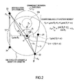
- FIG. 2 is a diagram illustrating a load that acts on a lower link of the multi-link internal combustion engine.
- FIG. 3 is a diagram illustrating the load that acts on the lower link.
- FIG. 4 is a diagram illustrating a relationship between a lower link aperture angle ⁇ and the geometry of the lower link.
- FIG. 5 is another diagram illustrating the relationship between the lower link aperture angle ⁇ and the geometry of the lower link.
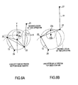
- FIGs. 6A and 6B are diagrams illustrating a moving locus of an upper pin when the lower link aperture angle ⁇ is smaller than ⁇ .
- FIG. 7 is a diagram illustrating the geometry of the lower link when a piston is at top dead center.
- FIGs. 8A and 8B are timing charts illustrating a piston stroke characteristic relative to a crank angle in a conventional multi-link internal combustion engine and a single link internal combustion engine.
- FIG. 9 is a schematic constitutional diagram of a crankshaft in a conventional serial four-cylinder engine.
- a piston 32 and a crankshaft 33 are connected by a plurality of links, an upper link 11 and a lower link 12. Further, a control link 13 is connected to the lower link 12.
- An upper end of the upper link 11 is connected to the piston 32 via a piston pin 21.
- the piston 32 reciprocates within a cylinder 31a of a cylinder block 31 after receiving combustion pressure.
- a lower end of the upper link 11 is connected to one end of the lower link 12 via an upper pin 22.
- crank pin 33b of the crankshaft 33 is inserted into a connecting hole in the center of the lower link 12.
- the crankshaft 33 includes a plurality of crank journals 33a and crank pins 33b.
- the crank journal 33a is supported rotatably on the cylinder block by a bearing cap.
- the crank pin 33b is eccentric to the crank journal 33a by a predetermined amount, and the lower link 12 is attached thereto.
- the lower link 12 rotates with the crank pin 33b as a central axis.
- a tip end of the control link 13 is connected to the lower link 12 via the control pin 23. Another end of the control link 13 is connected to the cylinder block 31 via an oscillation central shaft 24. The control link 13 oscillates about the oscillation central shaft 24.
- the geometry is set such that when these pistons are at bottom dead center, the load acting on the crank journal decreases.
- a crank pin load F 0 acts on the crank pin 33b.
- a control pin load F 3 acts on the control pin 23.
- An upper pin load F 6 is applied to the upper pin 22 from the piston 32.
- crank pin load F 0 The crank pin load F 0 , the control pin load F 3 , and the upper pin load F 6 are related as shown in the following Equation (1).
- Equation (2) Taking into account the counterbalance of a rotary moment of the control pin load F 3 and the upper pin load F 6 about the crank pin 33b, the following Equation (2) is established.
- Equation (3) When Equation (2) is transformed, the following Equation (3) is obtained.
- the upper pin load F 6 is determined by the combustion pressure and so on, and therefore cannot be adjusted. Furthermore, as L 4 / L 2 increases, a piston stroke amount relative to a crankshaft radius increases. In other words, the stroke length can be increased. To put it another way, to increase the stroke length of the piston stroke, L 4 / L 2 must be increased. However, when L 4 / L 2 increases, the control pin load F 3 increases, as shown in Equation (3). As a result, the crank pin load F 0 increases, leading to an increase in the load acting on the crank journal, as is evident from Equation (1).
- the geometry is set such that at piston bottom dead center, cos( ⁇ l + ⁇ ) is as small as possible.
- the control pin load F 3 decreases, the crank pin load F 0 decreases, and the load acting on the crank journal increases.
- a ratio F 0 / F 6 of the crank pin load F 0 to the upper pin load F 6 is defined as a load increase rate.
- the upper link 11 and the control link 13 are substantially parallel at piston bottom dead center.
- a line connecting the piston pin 21 and the upper pin 22 and a line connecting the control pin 23 and the oscillation central shaft 24 are substantially parallel.
- the direction of the crank pin load F 3 and the direction of the upper pin load F 6 are substantially identical. Accordingly, the sum of the magnitude of a vector F 3 and the magnitude of a vector F 6 equals the sum of the vector F 3 and the vector F 6 .
- Equation (4) is established.
- Equation (3) the load increase rate is expressed by the following Equation (5).
- a characteristic shown in FIG. 3 exists between the crank angle and the load increase rate.
- the load increase rate preferably varies as shown by the solid line in FIG. 3 . Therefore, in this invention, the lower link attitude angle ⁇ l and the lower link aperture angle ⁇ are set such that when the piston is at bottom dead center, cos( ⁇ l + ⁇ ) becomes smaller than cos( ⁇ l + ⁇ ). In so doing, the crank pin load F 0 decreases at piston bottom dead center, enabling a reduction in the load acting on the crank journal.
- crank pin load F 0 becomes excessively large at a timing when the piston acceleration reaches a maximum. Therefore, it is particularly preferable to set the lower link attitude angle ⁇ l and the lower link aperture angle ⁇ such that at the timing when the piston acceleration reaches a maximum, cos( ⁇ l + ⁇ ) becomes smaller than cos( ⁇ l + ⁇ ).
- cos( ⁇ l + ⁇ ) not only becomes smaller than cos( ⁇ l + ⁇ ) when the lower link aperture angle ⁇ is smaller than ⁇ .
- cos( ⁇ l + ⁇ ) also becomes smaller than cos( ⁇ l + ⁇ ) when the lower link aperture angle ⁇ is larger than ⁇ .
- the lower link 12 decreases in size.
- the position of the piston pin 21 lowers, as shown by a solid line in FIG. 5 , and as a result, the overall height of the engine decreases. Design should be performed appropriately, taking into account both of these characteristics.
- the oscillation central shaft 24 is preferably disposed in the region of a third quadrant (X ⁇ 0 and Y ⁇ 0). In so doing, a stroke direction secondary oscillation component of the piston acceleration decreases, whereby engine secondary oscillation accompanying lengthening of the piston stroke is reduced.
- the lower link aperture angle ⁇ is preferably set within a range that satisfies the following Equation (6).
- R 3 and R 6 shown in FIG. 7 are expressed by the following Equations (7-1) and (7-2).
- Equation (8) is then preferably established.
- R 6 can be reduced to a minimum, and as a result, the load can also be suppressed at top dead center.
Landscapes
- Engineering & Computer Science (AREA)
- Chemical & Material Sciences (AREA)
- Combustion & Propulsion (AREA)
- Mechanical Engineering (AREA)
- General Engineering & Computer Science (AREA)
- Transmission Devices (AREA)
- Cylinder Crankcases Of Internal Combustion Engines (AREA)
- Shafts, Cranks, Connecting Bars, And Related Bearings (AREA)
- Output Control And Ontrol Of Special Type Engine (AREA)
Applications Claiming Priority (1)
| Application Number | Priority Date | Filing Date | Title |
|---|---|---|---|
| JP2007210803A JP4882913B2 (ja) | 2007-08-13 | 2007-08-13 | マルチリンクエンジンのリンクジオメトリ |
Publications (3)
| Publication Number | Publication Date |
|---|---|
| EP2025894A2 true EP2025894A2 (de) | 2009-02-18 |
| EP2025894A3 EP2025894A3 (de) | 2014-04-23 |
| EP2025894B1 EP2025894B1 (de) | 2019-04-17 |
Family
ID=39926562
Family Applications (1)
| Application Number | Title | Priority Date | Filing Date |
|---|---|---|---|
| EP08014300.1A Ceased EP2025894B1 (de) | 2007-08-13 | 2008-08-11 | Verbrennungsmotor |
Country Status (3)
| Country | Link |
|---|---|
| US (1) | US7992529B2 (de) |
| EP (1) | EP2025894B1 (de) |
| JP (1) | JP4882913B2 (de) |
Cited By (2)
| Publication number | Priority date | Publication date | Assignee | Title |
|---|---|---|---|---|
| CN110671197A (zh) * | 2018-12-29 | 2020-01-10 | 长城汽车股份有限公司 | 发动机及具有其的车辆 |
| CN110671198A (zh) * | 2018-12-29 | 2020-01-10 | 长城汽车股份有限公司 | 发动机及具有其的车辆 |
Families Citing this family (3)
| Publication number | Priority date | Publication date | Assignee | Title |
|---|---|---|---|---|
| US9790853B2 (en) | 2013-05-20 | 2017-10-17 | Thomas Steve HUMPHRIES | Variable geometry power transfer for fluid flow machines |
| CN110671199B (zh) * | 2018-12-30 | 2021-07-06 | 长城汽车股份有限公司 | 可变压缩比机构与发动机 |
| CN110657024A (zh) * | 2018-12-30 | 2020-01-07 | 长城汽车股份有限公司 | 可变压缩比机构与发动机 |
Citations (2)
| Publication number | Priority date | Publication date | Assignee | Title |
|---|---|---|---|---|
| JP2001317383A (ja) | 2000-05-09 | 2001-11-16 | Nissan Motor Co Ltd | 内燃機関の可変圧縮比機構 |
| JP2007210803A (ja) | 2006-02-07 | 2007-08-23 | Shin Etsu Handotai Co Ltd | シリコン単結晶インゴットの製造方法及び製造装置並びにシリコン単結晶インゴット |
Family Cites Families (4)
| Publication number | Priority date | Publication date | Assignee | Title |
|---|---|---|---|---|
| US4131094A (en) * | 1977-02-07 | 1978-12-26 | Crise George W | Variable displacement internal combustion engine having automatic piston stroke control |
| US4517931A (en) * | 1983-06-30 | 1985-05-21 | Nelson Carl D | Variable stroke engine |
| JP2000073804A (ja) * | 1998-09-01 | 2000-03-07 | Toyota Autom Loom Works Ltd | 内燃機関及びその制御装置 |
| JP4430519B2 (ja) * | 2004-11-18 | 2010-03-10 | 本田技研工業株式会社 | ストローク特性可変エンジン |
-
2007
- 2007-08-13 JP JP2007210803A patent/JP4882913B2/ja not_active Expired - Fee Related
-
2008
- 2008-08-08 US US12/188,434 patent/US7992529B2/en active Active
- 2008-08-11 EP EP08014300.1A patent/EP2025894B1/de not_active Ceased
Patent Citations (2)
| Publication number | Priority date | Publication date | Assignee | Title |
|---|---|---|---|---|
| JP2001317383A (ja) | 2000-05-09 | 2001-11-16 | Nissan Motor Co Ltd | 内燃機関の可変圧縮比機構 |
| JP2007210803A (ja) | 2006-02-07 | 2007-08-23 | Shin Etsu Handotai Co Ltd | シリコン単結晶インゴットの製造方法及び製造装置並びにシリコン単結晶インゴット |
Cited By (3)
| Publication number | Priority date | Publication date | Assignee | Title |
|---|---|---|---|---|
| CN110671197A (zh) * | 2018-12-29 | 2020-01-10 | 长城汽车股份有限公司 | 发动机及具有其的车辆 |
| CN110671198A (zh) * | 2018-12-29 | 2020-01-10 | 长城汽车股份有限公司 | 发动机及具有其的车辆 |
| CN110671198B (zh) * | 2018-12-29 | 2021-07-20 | 长城汽车股份有限公司 | 发动机及具有其的车辆 |
Also Published As
| Publication number | Publication date |
|---|---|
| EP2025894B1 (de) | 2019-04-17 |
| US7992529B2 (en) | 2011-08-09 |
| JP2009046984A (ja) | 2009-03-05 |
| US20090044782A1 (en) | 2009-02-19 |
| JP4882913B2 (ja) | 2012-02-22 |
| EP2025894A3 (de) | 2014-04-23 |
Similar Documents
| Publication | Publication Date | Title |
|---|---|---|
| EP2463498B1 (de) | Mehrfachverknüpfungs-kolben-kurbel-mechanismus | |
| EP1593822B1 (de) | Brennkraftmaschine mit variablem Verdichtungsverhältnis | |
| US7392781B2 (en) | Crankshaft of piston crank mechanism | |
| EP2025894A2 (de) | Verbrennungsmotor | |
| EP2123869B1 (de) | Brennkraftmaschine mit variablem Kolbenhub und Multi-Gelenkgetriebe | |
| CN101418721B (zh) | 多连杆式发动机 | |
| US8733302B1 (en) | Variable compression ratio apparatus | |
| CN102465770B (zh) | 可变压缩比装置 | |
| JP5304187B2 (ja) | 内燃機関の複リンク式ピストンクランク機構 | |
| EP2960466B1 (de) | Verbrennungsmotor mit variabler verdichtung | |
| US4635596A (en) | Assembly of piston and connecting rod in internal-combustion engine | |
| US8826882B2 (en) | Lubricating structure of multi-link piston-crank mechanism for internal combustion engine | |
| JP4941231B2 (ja) | マルチリンクエンジンのリンクジオメトリ | |
| WO2009118614A1 (en) | Internal combustion engine | |
| JP2009215970A (ja) | 内燃機関のピストンクランク機構におけるロアリンク | |
| CN101424215B (zh) | 多连杆式发动机 | |
| JP4581675B2 (ja) | 内燃機関 | |
| JP2012092843A (ja) | マルチリンクエンジンのリンクジオメトリ | |
| JP2019148169A (ja) | 内燃機関の複リンク式ピストンクランク機構 | |
| JP5304878B2 (ja) | マルチリンクエンジンのリンクジオメトリ | |
| EP0834023B1 (de) | Pleuellager mit einem exzenter-und schraubfedermechanismus | |
| EP3279447A1 (de) | Verbrennungsmotor | |
| JPH04366071A (ja) | ピストンとコンロッドの連結構造 | |
| JP2018115647A (ja) | ピストン上、下死点及び圧縮比リミッタ付二分割コンロッドl形ヨーク式行程容積連続可変装置 | |
| JP2017089734A (ja) | 軸受およびコンロッドアセンブリ |
Legal Events
| Date | Code | Title | Description |
|---|---|---|---|
| PUAI | Public reference made under article 153(3) epc to a published international application that has entered the european phase |
Free format text: ORIGINAL CODE: 0009012 |
|
| 17P | Request for examination filed |
Effective date: 20080811 |
|
| AK | Designated contracting states |
Kind code of ref document: A2 Designated state(s): AT BE BG CH CY CZ DE DK EE ES FI FR GB GR HR HU IE IS IT LI LT LU LV MC MT NL NO PL PT RO SE SI SK TR |
|
| AX | Request for extension of the european patent |
Extension state: AL BA MK RS |
|
| PUAL | Search report despatched |
Free format text: ORIGINAL CODE: 0009013 |
|
| AK | Designated contracting states |
Kind code of ref document: A3 Designated state(s): AT BE BG CH CY CZ DE DK EE ES FI FR GB GR HR HU IE IS IT LI LT LU LV MC MT NL NO PL PT RO SE SI SK TR |
|
| AX | Request for extension of the european patent |
Extension state: AL BA MK RS |
|
| RIC1 | Information provided on ipc code assigned before grant |
Ipc: F02B 75/04 20060101AFI20140317BHEP |
|
| AKX | Designation fees paid |
Designated state(s): DE FR GB |
|
| AXX | Extension fees paid |
Extension state: AL Extension state: RS Extension state: MK Extension state: BA |
|
| 17Q | First examination report despatched |
Effective date: 20180208 |
|
| GRAP | Despatch of communication of intention to grant a patent |
Free format text: ORIGINAL CODE: EPIDOSNIGR1 |
|
| INTG | Intention to grant announced |
Effective date: 20190114 |
|
| GRAS | Grant fee paid |
Free format text: ORIGINAL CODE: EPIDOSNIGR3 |
|
| GRAA | (expected) grant |
Free format text: ORIGINAL CODE: 0009210 |
|
| AK | Designated contracting states |
Kind code of ref document: B1 Designated state(s): DE FR GB |
|
| REG | Reference to a national code |
Ref country code: GB Ref legal event code: FG4D |
|
| REG | Reference to a national code |
Ref country code: DE Ref legal event code: R096 Ref document number: 602008059748 Country of ref document: DE |
|
| REG | Reference to a national code |
Ref country code: DE Ref legal event code: R097 Ref document number: 602008059748 Country of ref document: DE |
|
| PLBE | No opposition filed within time limit |
Free format text: ORIGINAL CODE: 0009261 |
|
| STAA | Information on the status of an ep patent application or granted ep patent |
Free format text: STATUS: NO OPPOSITION FILED WITHIN TIME LIMIT |
|
| 26N | No opposition filed |
Effective date: 20200120 |
|
| PGFP | Annual fee paid to national office [announced via postgrant information from national office to epo] |
Ref country code: GB Payment date: 20220623 Year of fee payment: 15 |
|
| PGFP | Annual fee paid to national office [announced via postgrant information from national office to epo] |
Ref country code: FR Payment date: 20220609 Year of fee payment: 15 |
|
| PGFP | Annual fee paid to national office [announced via postgrant information from national office to epo] |
Ref country code: DE Payment date: 20220608 Year of fee payment: 15 |
|
| REG | Reference to a national code |
Ref country code: DE Ref legal event code: R119 Ref document number: 602008059748 Country of ref document: DE |
|
| GBPC | Gb: european patent ceased through non-payment of renewal fee |
Effective date: 20230811 |
|
| PG25 | Lapsed in a contracting state [announced via postgrant information from national office to epo] |
Ref country code: GB Free format text: LAPSE BECAUSE OF NON-PAYMENT OF DUE FEES Effective date: 20230811 |
|
| PG25 | Lapsed in a contracting state [announced via postgrant information from national office to epo] |
Ref country code: GB Free format text: LAPSE BECAUSE OF NON-PAYMENT OF DUE FEES Effective date: 20230811 Ref country code: FR Free format text: LAPSE BECAUSE OF NON-PAYMENT OF DUE FEES Effective date: 20230831 Ref country code: DE Free format text: LAPSE BECAUSE OF NON-PAYMENT OF DUE FEES Effective date: 20240301 |