EP2025927A2 - Dispositif d'allumage à décharge de plasma non équilibré - Google Patents
Dispositif d'allumage à décharge de plasma non équilibré Download PDFInfo
- Publication number
- EP2025927A2 EP2025927A2 EP08012962A EP08012962A EP2025927A2 EP 2025927 A2 EP2025927 A2 EP 2025927A2 EP 08012962 A EP08012962 A EP 08012962A EP 08012962 A EP08012962 A EP 08012962A EP 2025927 A2 EP2025927 A2 EP 2025927A2
- Authority
- EP
- European Patent Office
- Prior art keywords
- electrode
- plasma discharge
- equilibrium plasma
- ignition device
- insulating member
- Prior art date
- Legal status (The legal status is an assumption and is not a legal conclusion. Google has not performed a legal analysis and makes no representation as to the accuracy of the status listed.)
- Withdrawn
Links
- 238000002485 combustion reaction Methods 0.000 claims abstract description 181
- 239000000446 fuel Substances 0.000 claims abstract description 72
- 239000000203 mixture Substances 0.000 claims abstract description 51
- 239000000126 substance Substances 0.000 claims abstract description 7
- 230000007423 decrease Effects 0.000 claims description 15
- 230000007246 mechanism Effects 0.000 claims description 13
- 238000005265 energy consumption Methods 0.000 abstract description 3
- 230000000694 effects Effects 0.000 description 23
- 238000010586 diagram Methods 0.000 description 10
- 238000002347 injection Methods 0.000 description 8
- 239000007924 injection Substances 0.000 description 8
- 230000005684 electric field Effects 0.000 description 7
- 239000007789 gas Substances 0.000 description 6
- 230000002093 peripheral effect Effects 0.000 description 6
- 230000000087 stabilizing effect Effects 0.000 description 6
- 239000004020 conductor Substances 0.000 description 5
- 230000010355 oscillation Effects 0.000 description 5
- 230000007704 transition Effects 0.000 description 5
- 238000004891 communication Methods 0.000 description 4
- 239000003989 dielectric material Substances 0.000 description 4
- 238000010276 construction Methods 0.000 description 3
- 230000006866 deterioration Effects 0.000 description 3
- 230000008859 change Effects 0.000 description 2
- 239000000567 combustion gas Substances 0.000 description 2
- 230000006835 compression Effects 0.000 description 2
- 238000007906 compression Methods 0.000 description 2
- 230000006870 function Effects 0.000 description 2
- 230000020169 heat generation Effects 0.000 description 2
- 230000006872 improvement Effects 0.000 description 2
- 230000009257 reactivity Effects 0.000 description 2
- 230000004888 barrier function Effects 0.000 description 1
- 239000003990 capacitor Substances 0.000 description 1
- 230000015556 catabolic process Effects 0.000 description 1
- 239000013626 chemical specie Substances 0.000 description 1
- 238000001514 detection method Methods 0.000 description 1
- 238000007599 discharging Methods 0.000 description 1
- 238000010891 electric arc Methods 0.000 description 1
- 238000000034 method Methods 0.000 description 1
- 230000004048 modification Effects 0.000 description 1
- 238000012986 modification Methods 0.000 description 1
- 230000000644 propagated effect Effects 0.000 description 1
- 230000003134 recirculating effect Effects 0.000 description 1
- 230000000979 retarding effect Effects 0.000 description 1
- 230000001360 synchronised effect Effects 0.000 description 1
Images





Classifications
-
- F—MECHANICAL ENGINEERING; LIGHTING; HEATING; WEAPONS; BLASTING
- F02—COMBUSTION ENGINES; HOT-GAS OR COMBUSTION-PRODUCT ENGINE PLANTS
- F02P—IGNITION, OTHER THAN COMPRESSION IGNITION, FOR INTERNAL-COMBUSTION ENGINES; TESTING OF IGNITION TIMING IN COMPRESSION-IGNITION ENGINES
- F02P23/00—Other ignition
- F02P23/04—Other physical ignition means, e.g. using laser rays
-
- F—MECHANICAL ENGINEERING; LIGHTING; HEATING; WEAPONS; BLASTING
- F01—MACHINES OR ENGINES IN GENERAL; ENGINE PLANTS IN GENERAL; STEAM ENGINES
- F01L—CYCLICALLY OPERATING VALVES FOR MACHINES OR ENGINES
- F01L13/00—Modifications of valve-gear to facilitate reversing, braking, starting, changing compression ratio, or other specific operations
- F01L13/0015—Modifications of valve-gear to facilitate reversing, braking, starting, changing compression ratio, or other specific operations for optimising engine performances by modifying valve lift according to various working parameters, e.g. rotational speed, load, torque
- F01L13/0021—Modifications of valve-gear to facilitate reversing, braking, starting, changing compression ratio, or other specific operations for optimising engine performances by modifying valve lift according to various working parameters, e.g. rotational speed, load, torque by modification of rocker arm ratio
- F01L13/0026—Modifications of valve-gear to facilitate reversing, braking, starting, changing compression ratio, or other specific operations for optimising engine performances by modifying valve lift according to various working parameters, e.g. rotational speed, load, torque by modification of rocker arm ratio by means of an eccentric
-
- H—ELECTRICITY
- H01—ELECTRIC ELEMENTS
- H01T—SPARK GAPS; OVERVOLTAGE ARRESTERS USING SPARK GAPS; SPARKING PLUGS; CORONA DEVICES; GENERATING IONS TO BE INTRODUCED INTO NON-ENCLOSED GASES
- H01T13/00—Sparking plugs
- H01T13/50—Sparking plugs having means for ionisation of gap
-
- H—ELECTRICITY
- H01—ELECTRIC ELEMENTS
- H01T—SPARK GAPS; OVERVOLTAGE ARRESTERS USING SPARK GAPS; SPARKING PLUGS; CORONA DEVICES; GENERATING IONS TO BE INTRODUCED INTO NON-ENCLOSED GASES
- H01T13/00—Sparking plugs
- H01T13/54—Sparking plugs having electrodes arranged in a partly-enclosed ignition chamber
-
- H—ELECTRICITY
- H05—ELECTRIC TECHNIQUES NOT OTHERWISE PROVIDED FOR
- H05H—PLASMA TECHNIQUE; PRODUCTION OF ACCELERATED ELECTRICALLY-CHARGED PARTICLES OR OF NEUTRONS; PRODUCTION OR ACCELERATION OF NEUTRAL MOLECULAR OR ATOMIC BEAMS
- H05H1/00—Generating plasma; Handling plasma
- H05H1/24—Generating plasma
- H05H1/2406—Generating plasma using dielectric barrier discharges, i.e. with a dielectric interposed between the electrodes
-
- H—ELECTRICITY
- H05—ELECTRIC TECHNIQUES NOT OTHERWISE PROVIDED FOR
- H05H—PLASMA TECHNIQUE; PRODUCTION OF ACCELERATED ELECTRICALLY-CHARGED PARTICLES OR OF NEUTRONS; PRODUCTION OR ACCELERATION OF NEUTRAL MOLECULAR OR ATOMIC BEAMS
- H05H1/00—Generating plasma; Handling plasma
- H05H1/24—Generating plasma
- H05H1/2406—Generating plasma using dielectric barrier discharges, i.e. with a dielectric interposed between the electrodes
- H05H1/2418—Generating plasma using dielectric barrier discharges, i.e. with a dielectric interposed between the electrodes the electrodes being embedded in the dielectric
-
- H—ELECTRICITY
- H05—ELECTRIC TECHNIQUES NOT OTHERWISE PROVIDED FOR
- H05H—PLASMA TECHNIQUE; PRODUCTION OF ACCELERATED ELECTRICALLY-CHARGED PARTICLES OR OF NEUTRONS; PRODUCTION OR ACCELERATION OF NEUTRAL MOLECULAR OR ATOMIC BEAMS
- H05H1/00—Generating plasma; Handling plasma
- H05H1/24—Generating plasma
- H05H1/52—Generating plasma using exploding wires or spark gaps
-
- F—MECHANICAL ENGINEERING; LIGHTING; HEATING; WEAPONS; BLASTING
- F01—MACHINES OR ENGINES IN GENERAL; ENGINE PLANTS IN GENERAL; STEAM ENGINES
- F01L—CYCLICALLY OPERATING VALVES FOR MACHINES OR ENGINES
- F01L13/00—Modifications of valve-gear to facilitate reversing, braking, starting, changing compression ratio, or other specific operations
- F01L13/0015—Modifications of valve-gear to facilitate reversing, braking, starting, changing compression ratio, or other specific operations for optimising engine performances by modifying valve lift according to various working parameters, e.g. rotational speed, load, torque
- F01L13/0063—Modifications of valve-gear to facilitate reversing, braking, starting, changing compression ratio, or other specific operations for optimising engine performances by modifying valve lift according to various working parameters, e.g. rotational speed, load, torque by modification of cam contact point by displacing an intermediate lever or wedge-shaped intermediate element, e.g. Tourtelot
- F01L2013/0073—Modifications of valve-gear to facilitate reversing, braking, starting, changing compression ratio, or other specific operations for optimising engine performances by modifying valve lift according to various working parameters, e.g. rotational speed, load, torque by modification of cam contact point by displacing an intermediate lever or wedge-shaped intermediate element, e.g. Tourtelot with an oscillating cam acting on the valve of the "Delphi" type
-
- F—MECHANICAL ENGINEERING; LIGHTING; HEATING; WEAPONS; BLASTING
- F02—COMBUSTION ENGINES; HOT-GAS OR COMBUSTION-PRODUCT ENGINE PLANTS
- F02P—IGNITION, OTHER THAN COMPRESSION IGNITION, FOR INTERNAL-COMBUSTION ENGINES; TESTING OF IGNITION TIMING IN COMPRESSION-IGNITION ENGINES
- F02P3/00—Other installations
- F02P3/01—Electric spark ignition installations without subsequent energy storage, i.e. energy supplied by an electrical oscillator
-
- F—MECHANICAL ENGINEERING; LIGHTING; HEATING; WEAPONS; BLASTING
- F02—COMBUSTION ENGINES; HOT-GAS OR COMBUSTION-PRODUCT ENGINE PLANTS
- F02P—IGNITION, OTHER THAN COMPRESSION IGNITION, FOR INTERNAL-COMBUSTION ENGINES; TESTING OF IGNITION TIMING IN COMPRESSION-IGNITION ENGINES
- F02P5/00—Advancing or retarding ignition; Control therefor
-
- F—MECHANICAL ENGINEERING; LIGHTING; HEATING; WEAPONS; BLASTING
- F02—COMBUSTION ENGINES; HOT-GAS OR COMBUSTION-PRODUCT ENGINE PLANTS
- F02P—IGNITION, OTHER THAN COMPRESSION IGNITION, FOR INTERNAL-COMBUSTION ENGINES; TESTING OF IGNITION TIMING IN COMPRESSION-IGNITION ENGINES
- F02P9/00—Electric spark ignition control, not otherwise provided for
- F02P9/002—Control of spark intensity, intensifying, lengthening, suppression
- F02P9/007—Control of spark intensity, intensifying, lengthening, suppression by supplementary electrical discharge in the pre-ionised electrode interspace of the sparking plug, e.g. plasma jet ignition
Definitions
- This invention relates to an ignition device which ignites a fuel mixture to be combusted by an internal combustion engine by non-equilibrium plasma discharge.
- JPH 10-141191A published by the Japan Patent Office in 1996 proposes an ignition device which ignites a fuel mixture in a combustion chamber of an internal combustion engine through application of non-equilibrium plasma discharge.
- the non-equilibrium plasma discharge is also called low-temperature plasma discharge or corona discharge.
- the ignition device comprises two electrodes which effect a high-voltage discharge in the combustion chamber, and a pulse power source portion for impressing a short-pulse-width high-voltage alternating current between the electrodes to cause the non-equilibrium plasma discharge between the electrodes, and then generates equilibrium plasma discharge due to thermalization plasma, thereby igniting the fuel mixture in the combustion chamber.
- the equilibrium plasma discharge due to the thermalization plasma is also called high-temperature plasma discharge or arc discharge.
- the discharge mode undergoes transition from the non-equilibrium plasma discharge to the equilibrium plasma discharge.
- the value of an electric current flowing between the electrodes is small, and it is possible to form high-energy electrons with low consumption energy.
- a large quantity of electric current flows through a portion bridged by the equilibrium plasma discharge.
- the ignition performance is improved, an increase in power consumption due to the discharge is inevitable.
- this invention provides an ignition device which performs a spark ignition of a fuel mixture in a combustion chamber of an internal combustion engine.
- the device comprises a first electrode, a second electrode, and an insulating member which is formed from dielectric substance and interposed between the first electrode and the second electrode.
- the insulating member promotes non-equilibrium plasma discharge between the dielectric and one of the first electrode and the second electrode when an alternating current is impressed between the first electrode and the second electrode.
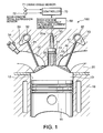
- FIG. 1 is an enlarged schematic longitudinal sectional view of essential parts of an internal combustion engine, illustrating the construction of an ignition device according to this invention.
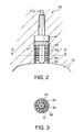
- FIG. 2 is a side view, inclusive of a partial longitudinal sectional view, of a spark plug according to this invention.
- FIG. 3 is a cross-sectional view of the spark plug taken along the line III-III of FIG. 2 .
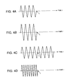
- FIGS. 4A - 4D are diagrams illustrating a method of increasing the discharge energy of the non-equilibrium plasma discharge.
- FIGS. 5A and 5B are a side view, inclusive of a partial longitudinal sectional view, of a conventional spark plug, and a timing chart showing number of times that the non-equilibrium plasma discharge occurs.
- FIGS. 6A and 6B are a side view, inclusive of a partial longitudinal sectional view, of a spark plug according to this invention, and a timing chart showing number of times that the non-equilibrium plasma discharge occurs.
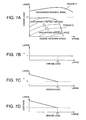
- FIGS. 7A - 7D are diagrams illustrating contents of maps of a discharged energy, an excess air factor, and an exhaust gas recirculation (EGR) rate of the internal combustion engine stored in a controller according to this invention.
- EGR exhaust gas recirculation
- FIG. 8 is a side view, inclusive of a partial longitudinal sectional view, of a spark plug according to a second embodiment of this invention.
- FIG. 9 is similar to FIG. 6 but shows a third embodiment of this invention.
- FIG. 10 is similar to FIG. 6 but shows a fourth embodiment of this invention.
- FIG. 11 is similar to FIG. 6 but shows a fifth embodiment of this invention.
- FIG. 12 is an enlarged schematic longitudinal sectional view of essential parts of an internal combustion engine, illustrating the construction of an ignition device according to a sixth embodiment of this invention.
- FIGS. 13A and 13B are schematic longitudinal sectional views of essential parts of the internal combustion engine, illustrating how the ignition device according to the sixth embodiment of this invention causes the non-equilibrium plasma discharge.
- FIG. 14 is a perspective view of a variable valve mechanism provided in the internal combustion engine to which the ignition device according to the sixth embodiment of this invention is applied.
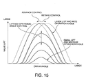
- FIG. 15 is a diagram illustrating changes in valve lift of an intake valve according to the variable valve mechanism.
- FIG. 16 is a diagram illustrating a discharged energy map stored in a controller according to the sixth embodiment of this invention.
- FIGS. 17A - 17C are diagrams illustrating the excess air factor, the EGR rate, and the intake valve close (IVC) timing in an operation range of high-engine-rotation-speed/high-engine-load in the internal combustion engine equipped with the ignition device according to the sixth embodiment of this invention.
- FIGS. 18A - 18C are diagrams illustrating the excess air factor, the EGR rate, and the IVC timing in an operation range of low-engine-rotation-speed/low-engine-load in the internal combustion engine equipped with the ignition device according to the sixth embodiment of this invention.
- FIG. 19 is an enlarged schematic longitudinal sectional view of essential parts of an internal combustion engine, illustrating the construction of an ignition device according to a seventh embodiment of this invention.
- FIGS. 20A and 20B are schematic longitudinal sectional views of essential parts of the internal combustion engine, illustrating how the ignition device according to the seventh embodiment of this invention effects the non-equilibrium plasma discharge.
- FIG. 21 is a diagram illustrating a content of a discharged energy map stored in a controller according to the seventh embodiment of this invention.
- FIGS. 22A - 22C are diagrams illustrating the excess air factor, the EGR ratio, and the IVC timing in an operation range of high-engine-rotation-speed/high-engine-load in the internal combustion engine equipped with the ignition device according to the seventh embodiment of this invention.
- FIGS. 23A - 23C are diagrams illustrating the excess air factor, the EGR ratio, and the IVC timing in an operation range of low-engine-rotation-speed/low-engine-load in the internal combustion engine equipped with the ignition device according to the seventh embodiment of this invention.
- FIG. 24 is a timing chart illustrating radical generation discharge executed by the ignition device according to the seventh embodiment of this invention.
- FIG. 25 is a diagram illustrating a content of a radical generation discharge region map stored in the controller according to the seventh embodiment of this invention.
- a non-equilibrium plasma discharge type vehicle internal combustion engine 100 comprises a cylinder block 10, and a cylinder head 20 provided on the upper side of the cylinder block 10.
- the internal combustion engine 100 is a four-stroke-cycle multicylinder engine.
- a cylinder 12 is formed in the cylinder block 10 to accommodate a piston 11.
- a combustion chamber 13 is formed by a crown surface of the piston 11, a wall surface of the cylinder 12, and a bottom surface of the cylinder head 20. When fuel mixture burns in the combustion chamber 13, the piston 11 reciprocates within the cylinder 12 under a combustion pressure.
- An intake port 30 for supplying fuel mixture to the combustion chamber 13 and an exhaust port 40 for expelling exhaust gas from the combustion chamber 13 are formed in the cylinder head 20.
- the intake port 30 is equipped with an intake valve 31.
- the intake valve 31 is driven by a cam 33 formed integrally with an intake camshaft 32, and opens and closes the intake port 30 as the piston 11 moves up and down.
- a fuel injector 34 for injecting fuel is installed in the intake port 30.
- the exhaust port 40 is equipped with an exhaust valve 41.
- the exhaust valve 41 is driven by a cam 43 formed integrally with an exhaust camshaft 42, and opens and closes the exhaust port 40 as the piston 11 moves up and down.
- An exhaust passage for discharging exhaust gas to the exterior is connected to the exhaust port 40, and an exhaust gas recirculation (EGR) device connected to the exhaust passage causes a part of the exhaust gas to be recirculated into a flow of the intake air which is aspirated into the combustion chamber 13 through the intake port 30.
- EGR exhaust gas recirculation
- a spark plug 50 is installed between the intake port 30 and the exhaust port 40 of the cylinder head 20 so as to face the combustion chamber 13.
- the spark plug 50 is equipped with a center electrode 51 as a first electrode, a cylindrical electrode 52 as a second electrode, an insulating member 53, and an outer shell 54, and is adapted to ignite fuel mixture through the non-equilibrium plasma discharge.
- the spark plug 50 is accommodated in a recess formed in the cylinder head 20, and is fixed to the cylinder head 20 via an outer shell 54 provided at the center in the axial direction.
- An ignition chamber 55 communicating with the combustion chamber 13 is formed between the insulating member 53 and the cylindrical electrode 52 of the spark plug 50.
- the cylindrical electrode 52 is formed of a conductive material, and protrudes downwards from the outer shell 54.
- the insulating member 53 comprises a capsule-like dielectric substance, and extends vertically through the outer shell 54 to protrude into the cylindrical electrode 52.
- the center electrode 51 is formed of a bar-like conductor, and is arranged on the inner side of the insulating member 53.
- An annular gap between the cylindrical electrode 52 and the insulating member 53 forms the ignition chamber 55.
- the cylinder block 10, the piston 11, and the cylinder head 20 are all formed of a conductive material, and are connected to the ground.
- the cylindrical electrode 52 is connected to the ground via the cylinder head 20.
- a terminal 51a is mounted to the upper end of the center electrode 51.
- a high-voltage/high-frequency alternate current generator 60 is connected to the terminal 51a.
- the high-voltage/high-frequency alternate current generator 60 impresses an alternating current according to the engine operation state between the terminal 51a and the ground.
- the high-voltage/high-frequency alternate current generator 60 is controlled by a controller 70.
- the controller 70 is constituted by a microcomputer comprising a central processing unit (CPU), a read-only memory (ROM), a random access memory (RAM), and an input/output interface (I/O interface).
- the controller 70 may be constituted by a plurality of microcomputers.
- Detection data from a crank angle sensor 71 for producing a crank angle signal for each predetermined crank angle of the internal combustion engine 100, and an accelerator pedal depression sensor 72 for detecting the operating amount of an accelerator pedal provided in the vehicle are input into the controller 70 as signals.
- the crank angle signal is used as a signal representative of an engine rotation speed of the internal combustion engine 100.
- the operating amount of the accelerator pedal is used as a signal representative of an engine load of the internal combustion engine 100.
- the controller 70 controls a voltage value, an impression time period, a frequency, and an impression timing of the alternating current output from the high-voltage/high-frequency alternate current generator 60 to control the ignition of the spark plug 50 and the discharge energy of the non-equilibrium plasma discharge.
- the fuel injector 34 injects fuel into the intake port 30.
- the pressure in the combustion chamber 13 becomes lower than the pressure in the intake port 30.
- the intake valve 31 is opened in this state, fuel mixture flows from the intake port 30 into the combustion chamber 13 due to the difference in pressure between the intake port 30 and the combustion chamber 13.
- the fuel mixture After the intake valve 31 is closed, the fuel mixture is compressed due to the rise of the piston 11, and a portion of the fuel mixture flows into the ignition chamber 55. Immediately before the piston 11 reaches the compression top dead center, the fuel mixture which has flowed into the ignition chamber 55 is ignited through the non-equilibrium plasma discharge of the spark plug 50. In this way, the flame generated in the ignition chamber 55 is propagated to the combustion chamber 13 to burn the fuel mixture in the combustion chamber 13.
- the spark plug 50 when an alternating current is impressed to the spark plug 50 by the high-voltage/high-frequency alternate current generator 60, the spark plug 50 effects a transitional non-equilibrium plasma discharge, or in other words dielectric barrier discharge, between the insulating member 53 and the cylindrical electrode 52 preceding the equilibrium plasma discharge. As a result, a number of streamers 56 are generated in both the axial direction and the radial direction.
- the spark plug 50 increases the electron temperature of the ignition chamber 55 to thereby enhance the molecular activity thereof. As a result, there is realized simultaneous ignition at a number of points in a large ignition space. This type of ignition will be referred to as volumetric ignition.
- the center electrode 51 is formed within the insulating member 53 formed from dielectric substance. It is therefore possible to suppress transition of the discharge between the insulating member 53 and the cylindrical electrode 52 from the non-equilibrium plasma discharge to the equilibrium plasma discharge even when the discharge energy of the center electrode 51 increases,
- the discharge energy of the non-equilibrium plasma discharge generated at the spark plug 50 varies according to the voltage value, the impression time period, and the frequency of the alternating current from the high-voltage/high-frequency alternate current generator 60.
- a reference waveform of the alternating current shown in FIG. 4A an increase in the voltage value of the alternating current as shown in FIG. 4B , an increase in the impression time period of the alternating current as shown in FIG. 4C , or an increase in the frequency of the alternating current as shown in FIG. 4D , leads to an increase in the discharge energy of the spark plug 50.
- FIGS. 5A and 5B show a conventional spark plug 500 that effects the equilibrium plasma discharge between an electrode 501 and an electrode 502, and a discharge timing thereof.
- the conventional spark plug 500 when the absolute value of an electric field V0 formed between the electrodes by impressed alternating current reaches a predetermined dielectric breakdown electric field Va, the equilibrium plasma discharge is effected between the electrodes 501 and 502. Thus, the conventional spark plug 500 effects the equilibrium plasma discharge four times during a given discharge period t.
- FIGS. 6A and 6B show the spark plug 50 of this invention, and a discharge timing thereof.
- the center electrode 51 is accommodated within the insulating member 53 formed from dielectric substance, and the insulating member 53 functions as a kind of capacitor. It is therefore possible to store electric charge in the surface of the insulating member 53 after the non-equilibrium plasma discharge.
- FIG. 6B at the point in time when the absolute value of the difference between the electric field V0 according to the impressed alternating current and the electric field Vw according to the dielectric surface electric charge of the insulating member 53 reaches a predetermined non-equilibrium plasma discharge start electric field Vd, the non-equilibrium plasma discharge is effected between the insulating member 53 and the cylindrical electrode 52.
- the non-equilibrium plasma discharge is effected eight times during the discharge period t .
- FIG. 6A in the spark plug 50, streamers are formed in a large number of positions within the ignition chamber 55.
- the spark plug 50 effects volumetric ignition on fuel mixture inside the ignition chamber 55, but it effects discharge a larger number of times during the same discharge period t as compared with the conventional spark plug 500.
- the spark plug 50 according to this invention realizes a more powerful ignition performance.
- the spark plug 50 can effect discharge a still larger number of times. More specifically, when, in FIG. 6B , the difference between the peak of the electric field V0 according to the impressed alternating current and the non-equilibrium plasma discharge start electric field Vw exceeds Vd, the number of times that the non-equilibrium plasma discharge occurs further increases within the same cycle.
- the internal combustion engine 100 equipped with the spark plug 50 is operated based on the operation maps of which the contents are shown in FIGS. 7A - 7D .
- the operation range for the internal combustion engine 100 is divided into a region P of high-rotation-speed/high-load and a region Q of low-rotation-speed/low-load.
- the internal combustion engine 100 is controlled such that the excess air factor ⁇ is equal to 1, or in other words the fuel injection amount or the intake air volume of the internal combustion engine 100 is controlled such that the air-fuel ratio of the fuel mixture becomes equal to the stoichiometric air-fuel ratio.
- the controller 70 controls the high-voltage/highfrequency alternate current generator 60 such that the discharged energy is at a fixed level irrespective of the engine operation state.
- the excess air factor ⁇ is controlled to be equal to 1 such that the fuel mixture in the ignition chamber 55 has a composition which is easy to ignite.
- the discharged energy of the non-equilibrium plasma discharge of the spark plug 50 is set smaller than that during the operation under low-rotation-speed/low-load described below.
- the internal combustion engine 100 performs lean combustion while varying the excess air factor ⁇ according to the engine load. Specifically, when the engine load is smaller than a predetermined value T1 , the fuel injection amount or the intake air volume is controlled such that the excess air factor ⁇ increases as the engine load decreases. As shown in FIG. 7A , the predetermined value T1 is determined from a maximum load in the region Q. In the lean combustion in the region Q, the ignition performance deteriorates if the same volumetric ignition is effected with the same discharged energy as in the region P.
- the controller 70 sets the discharged energy of the non-equilibrium plasma discharge of the spark plug 50 greater than that in the region P.
- the controller 70 controls the voltage value, the wave number, etc. of the impressed alternating current in the region Q shown in FIG. 7A to increase the discharged energy of the non-equilibrium plasma discharge as the engine load becomes smaller and the engine rotation speed becomes higher, thereby stabilizing the ignition performance of the spark plug 50.
- the internal combustion engine 100 performs lean combustion during the operation under low-rotation-speed/low-load corresponding to the region Q, it is also possible to perform diluted combustion by recirculating a part of the exhaust gas to the intake port 30 by the EGR device.
- the EGR rate is controlled to increase as the engine load becomes smaller with respect to the predetermined value T1.
- Control of the excess air factor ⁇ and the EGR rate of the internal combustion engine 100 is performed by a control device supplied as a separate unit, but it is also possible to set up the controller 70 to control these factors.
- the controller 70 sets the discharged energy of the non-equilibrium plasma of the spark plug 50 during the operation in the region Q of low rotation speed and low load larger than that during the operation in the region P of high rotation speed and high load. Further, also in the region Q, the controller 70 adjusts the voltage value, the wave number, etc. of the impressed alternating current such that the discharged energy of the non-equilibrium plasma discharge increases as the engine rotation speed increases at low load.
- the spark plug 50 of the internal combustion engine 100 effects volumetric ignition in the ignition chamber 55, thereby forming a plurality of streamers 56 from the insulating member 53 toward the cylindrical electrode 52.
- a condition which is likely to lead to unstable combustion such as lean combustion or diluted combustion
- the ignition performance with respect to the fuel mixture in the combustion chamber 13 increases, and the combustion period for the fuel mixture can be shortened, making it possible to substantially expand the lean combustion limit.
- the non-equilibrium plasma discharge it is possible to ignite the fuel mixture with low energy consumption.
- the insulating member 53 formed form dielectric substance covers the center electrode 51 in the spark plug 50, transition from the non-equilibrium plasma discharge to the equilibrium plasma discharge can be suppressed even when the discharged energy increases. Effecting ignition solely through the non-equilibrium plasma discharge without causing transition to the equilibrium plasma discharge is advantageous in that it makes it possible to suppress the energy consumed by the spark plug 50.
- the voltage value, the wave number, etc. of the impressed alternating current are controlled such that the discharged energy of the spark plug 50 increases as the engine load decreases.
- the voltage value, the wave number, etc. of the impressed alternating current are controlled such that the discharged energy of the spark plug 50 increases as the engine load decreases.
- the voltage value, the wave number, etc. of the impressed alternating current are controlled such that the discharged energy of the spark plug 50 increases as the engine rotation speed increases.
- the voltage value, the wave number, etc. of the impressed alternating current are controlled such that the discharged energy of the spark plug 50 increases as the engine rotation speed increases.
- the voltage value, the wave number, etc. of the impressed alternating current are controlled such that the discharged energy of the spark plug 50 increases as the air-fuel ratio becomes leaner, or as the EGR rate becomes higher.
- the voltage value, the wave number, etc. of the impressed alternating current are controlled such that the discharged energy of the spark plug 50 increases as the air-fuel ratio becomes leaner, or as the EGR rate becomes higher.
- the non-equilibrium plasma discharge period increases, resulting in an increase in discharged energy. According to this setting, it is possible to enhance the ignition performance under a condition in which the fuel mixture density in the combustion chamber changes with passage of time, which is likely to cause ignition fluctuation, as in the case of diluted combustion, in which the fuel mixture density in the combustion chamber 13 is uneven.
- the ignition device according to this embodiment differs from that of the first embodiment in that a plurality of projections 52a are provided on the cylindrical electrode 52 of the spark plug 50.
- the other components of this ignition device are identical to those of the ignition device according to the first embodiment of this invention.
- the spark plug 50 is provided with a plurality of projections 52a arranged in the axial and radial directions on the inner peripheral surface of the cylindrical electrode 52 to protrude into the ignition chamber 55.
- the projections 52a are formed of a conductive material, and the distal ends of all the projections 52a are at a same distance from the insulating member 53.
- the non-equilibrium plasma discharge is effected between the projections 52a of the cylindrical electrode 52 and the insulating member 53.
- the number of streamers 56 formed in the ignition chamber 55 is identical to the number of the projections 52a.
- the ignition device according to the second embodiment of this invention provides the same effects as those of the first embodiment. Further, since it can generate the equilibrium plasma discharge at required positions arbitrarily in the ignition chamber 55, the ignition performance is further enhanced.
- the cylindrical electrode 52 instead of providing the cylindrical electrode 52 with a plurality of projections 52a, it is also possible to provide the insulating member 53, which covers the center electrode 51, with a plurality of projections formed from dielectric material.
- the insulating member 53 of the spark plug 50 is in contact with the inner periphery of the cylindrical electrode 52, and covers the cylindrical electrode 52. In other words, the insulating member 53 covers not the first electrode but the second electrode.
- the other components of this ignition device are identical to those of the ignition device according to the first embodiment.
- the insulating member 53 is formed into a cylindrical shape having a bottom.
- the insulating member 53 is fitted into the inner peripheral surface of the cylindrical electrode 52.
- the lower end of the insulating member 53 extends lower than the lower end of the cylindrical electrode 52 and protrudes into the combustion chamber 13.
- the space between the bar-like center electrode 51 and the insulating member 53 functions as the ignition chamber 55.
- the ignition chamber 55 communicates with the combustion chamber 13 via an opening directed to the combustion chamber 13.
- the non-equilibrium plasma discharge occurs between the center electrode 51 and the insulating member 53, forming a plurality of streamers 56 arranged axially and radially.
- the non-equilibrium plasma discharge occurs between the center electrode 51 and the insulating member 53, forming a plurality of streamers 56 arranged axially and radially.
- the lower end of the insulating member 53 protrudes downwards beyond the lower end of the cylindrical electrode 52, it is possible to suppress the generation of the equilibrium plasma discharge between the forward end of the center electrode 51 and the forward end of the cylindrical electrode 52 even when the discharged energy of the non-equilibrium plasma discharge is increased.
- a plurality of projections 53a protruding into the ignition chamber 55 are arranged axially and radially on the inner periphery of the insulating member 53 of the third embodiment of this invention.
- the other components of this ignition device are identical to those of the ignition device according to the third embodiment.
- the plurality of projections 53a are formed from dielectric material, and the distance between the distal ends of the projections 53a and the center electrode 51 is set to be constant.
- the non-equilibrium plasma discharge occurs between the projections 53a of the insulating member 53 and the center electrode 51.
- the number of the streamers 56 formed in the ignition chamber 13 is identical to that of the projections 53a.
- the ignition device according to this embodiment brings about the same effect as that of the third embodiment. Further, since it can generate the equilibrium plasma discharge at required positions arbitrarily in the ignition chamber 55, it is possible to attain a still higher ignition performance.
- the distance between the projections 53a and the center electrode 51 can be set arbitrarily, the distance between the inner peripheral surface of the insulating member 53 and the center electrode 51 can be set large even when the gap required for the non-equilibrium plasma discharge is small, thereby suppressing the heat loss of the initial flame.
- the lower end of the cylindrical electrode 52 is open to the combustion chamber 13.
- the cylindrical electrode 52 is formed to have a closed lower end 52c protruding toward the combustion chamber 13.
- An auxiliary combustion chamber 57 is defined between the lower end 52c and the insulating member 53.
- a plurality of communication holes 52b for establishing communication between the combustion chamber 13 and the auxiliary combustion chamber 57 are provided.
- the other components of this ignition device are identical to those of the ignition device according to the first embodiment.
- a portion of the fuel mixture aspirated into the combustion chamber 13 flows into the auxiliary combustion chamber 57 via the communication holes 52b.
- the fuel mixture which has flowed into the auxiliary combustion chamber 57 undergoes volumetric ignition by the non-equilibrium plasma discharge generated between the cylindrical electrode 52 and the insulating member 53 of the spark plug 50.
- the combustion gas generated in the auxiliary combustion chamber 57 is radiated in a torch-like fashion into the combustion chamber 13 via the communication holes 52b, igniting the fuel mixture in the combustion chamber.
- this mode of ignition will be referred to as torch ignition.
- volumetric ignition is effected on the fuel mixture in the auxiliary combustion chamber 57, and hence this embodiment brings about preferable effects as those of the first embodiment of this invention. Further, since torch ignition is effected on the fuel mixture in the combustion chamber 13 by using the combustion gas generated in the auxiliary combustion chamber 57, the combustion of the fuel mixture in the combustion chamber 13 is further promoted. As a result the lean burn limit can be expanded with respect to the case of the first embodiment.
- FIG. 12 Referring to FIG. 12 , FIGS. 13A and 13B , FIGS. 14 - 16 , FIGS 17A - 17C , and FIGS. 18A - 18C a sixth embodiment of this invention will be described.
- the center electrode 51 and the insulating member 53 of the first embodiment are caused to protrude into the combustion chamber 13.
- the wall surface of the cylinder head 20 and the crown surface 11a of the piston 11 constitute the second electrode.
- the spark plug 50 causes the non-equilibrium plasma discharge within the combustion chamber 13 to effect volumetric ignition on the fuel mixture in the combustion chamber 13.
- the spark plug 50 effects the non-equilibrium plasma discharge at least in one of the two spaces, a space A between the insulating member 53 and the crown surface 11a of the piston 11, and a space B between the insulating member 53 and the wall surface 21 of the cylinder head 20 covering the combustion chamber 13.
- volumetric ignition is effected on the fuel mixture inside the combustion chamber 13.
- the non-equilibrium plasma discharge is to be effected in the space A or the non-equilibrium plasma discharge is to be effected in the space B is determined by the position of the piston when the alternating current is impressed to the spark plug 50.
- the timing at which the alternating current is impressed to the spark plug 50 in relation to the stroke position of the piston 11 it is possible to select the discharge space for the non-equilibrium plasma discharge.
- the ignition device according to this embodiment is applied to an internal combustion engine 101 equipped with a variable valve mechanism 200, which makes the valve characteristics such as the lift amount and operation angle of the intake valve 31 variable.
- the internal combustion engine 101 is a four-stroke-cycle multicylinder engine and executes Miller-cycle engine operation according to the engine operating state.
- variable valve mechanism 200 Referring to FIGS. 14 and 15 , the variable valve mechanism 200 will be described.
- each of the cylinders is equipped with two intake ports 30 and two intake valves 31.
- the two intake valves 31 are opened and closed in synchronism with each other by a single variable valve mechanism 200.
- variable valve mechanism 200 comprises two oscillating cams 210, an oscillating cam driving mechanism 220 for oscillating the oscillating cams 210, and a lift amount varying mechanism 230 capable of continuously changing the lift amounts of the two intake valves 31.
- the oscillating cams 210 are fitted onto the outer periphery of a drive shaft 221 extending in the cylinder row direction of the internal combustion engine 101, so as to be free to rotate.
- the oscillating cams 210 open and close the intake valves 31 via valve lifters 211.
- the two oscillating cams 210 are connected in the same phase via a connecting cylinder 221a which is supported on the outer periphery of the drive shaft 221 so as to be free to rotate.
- the two oscillating cams 210 operate in synchronism with each other.
- An eccentric cam 222 is fixed to the drive shaft 221 by press-fitting or the like.
- the eccentric cam 222 has a circular outer peripheral surface, and the center of its outer peripheral surface is offset from the axis of the drive shaft 221 by a predetermined amount.
- the eccentric cam 222 rotates eccentrically around the axis of the drive shaft 21.
- An annular section 224 at a base end of a first link 223 is fitted onto the outer peripheral surface of the eccentric cam 222 so as top be free to rotate.
- a lift amount varying mechanism 230 comprises a control shaft 231 and a rocker arm 226.
- the rocker arm 226 is supported on the outer periphery of an eccentric cam 232 formed on the control shaft 231, so as to be free to oscillate.
- the rocker arm 226 have two ends extending radially.
- a tip end of the first link 223 is connected to one end of the rocker arm 226 via a connecting pin 225.
- An upper end of a second link 228 is connected to the other end of the rocker arm 226 via a connecting pin 227.
- a lower end of the second link 228 is connected via a connecting pin 229 to the oscillating cams 210 for driving the intake valves 31.
- the eccentric cam 222 makes eccentric rotation, whereby the first link 223 oscillates vertically.
- the rocker arm 226 oscillates around the axis of the eccentric cam 232
- the second link 228 oscillates vertically
- the two oscillating cams 210 are oscillated within a predetermined rotation angle range via the connecting cylinder 221 a.
- the two intake valves 31 open and close the intake ports 30 synchronously.
- a cam sprocket which is rotated by the crankshaft is connected to one end of the drive shaft 221.
- the drive shaft 221 and the cam sprocket are constructed so as to allow adjustment of the phase in their rotating direction. By changing the phase in the rotating direction of the drive shaft 221 and the cam sprocket, it is possible to adjust the phase in the rotating direction of the crankshaft and the drive shaft 221.
- One end of the control shaft 231 is connected to a rotary actuator via a gear or the like.
- the axis of the eccentric cam 232 constituting the oscillation center of the rocker arm 226 swings around the rotation center of the control shaft 231, with the result that the fulcrum of the rocker arm 226 is displaced.
- the attitudes of the first link 223 and the second link 228 are changed, and the distance between the oscillation center of the oscillating cams 210 and the rotation center of the rocker arm 226 changes, resulting in a change in the oscillation characteristics of the oscillating cams 210.
- valve characteristics of the intake valves 31 driven by the variable valve mechanism 200 will be described.
- the solid lines in the drawing indicate changes in the lift amount of the intake valves 31 when the rotation angle of the control shaft 231 is varied, and the broken lines in the drawing indicate changes in the lift positions of the intake valves 31 when the phase in the rotating direction of the drive shaft 221 and the cam sprocket is varied.
- the variable valve mechanism 200 by changing the rotation angle of the control shaft 231 and the phase in the rotating direction of the drive shaft 221 with respect to the cam sprocket, it is possible to continuously change the valve characteristics of the intake valves 31 such as the lift amount and the operation angle thereof.
- this internal combustion engine 101 is identical to those of the internal combustion engine 100 described with reference to the first embodiment.
- variable valve mechanism 200 opens and closes the intake valves 31, whereby the valve characteristics are changed at the time of low-rotation-speed/low-load operation to execute Miller-cycle engine operation.
- the operation range for the internal combustion engine 101 can be divided into a region P where high-rotation-speed/high-load operation is performed and a region Q where low-rotation-speed/low-load operation is performed.
- the fuel injection amount of the internal combustion engine 101 is controlled such that the excess air factor ⁇ is equal to 1.0, or in other words the air-fuel ratio is equal to the stoichiometric air-fuel ratio, irrespective of the engine operation state.
- the EGR rate is controlled according to the engine load, and the internal combustion engine 101 performs diluted combustion.
- the EGR rate is set to decrease as the engine load increases.
- the internal combustion engine 101 performs no Miller-cycle engine operation.
- the intake valve close (IVC) timing of the intake valves 31 is set so as to be retarded with respect to the piston bottom dead center.
- the controller 70 adjusts the voltage value, the wave number, etc. of the impressed alternating current so as to increase the discharged energy in the non-equilibrium plasma discharge, thereby stabilizing the ignition performance.
- the discharged energy in the non-equilibrium plasma discharge of the spark plug 50 in the region P is set smaller than that in the region Q, where low-rotation-speed/low-load operation is conducted.
- the fuel injection amount of the internal combustion engine 101 is controlled such that the excess air factor ⁇ is equal to 1.0, or in other words the air-fuel ratio is equal to the stoichiometric air-fuel ratio, independently of the engine operation state.
- the EGR rate is maintained at a fixed level, and the internal combustion engine 101 performs diluted combustion.
- the internal combustion engine 101 performs Miller-cycle engine operation.
- the IVC timing is advanced with respect to the piston bottom dead center, and the intake of fuel mixture is stopped during the intake stroke.
- the advancement amount of the IVC timing of the intake valves 31 is adjusted so as to become larger as the load decreases, causing the intake valves 31 to be closed at an early stage. Due to Miller-cycle engine operation, the pump loss is reduced even under low load, making it possible to reduce the fuel consumption.
- Control of the excess air factor ⁇ , the EGR rate, or the IVC timing of the internal combustion engine 101 is conducted by a control device provided as a separate unit, but it is also possible to set up the controller 70 to control these factors.
- the controller 70 sets the discharged energy of the non-equilibrium plasma discharge of the spark plug 50 larger than that in the region P, where high-rotation-speed/high-load operation is performed. By thus increasing the discharged energy of the spark plug 50, which effects volumetric ignition on the fuel mixture in the combustion chamber 13, the ignition performance of the internal combustion engine 101 is stabilized.
- the non-equilibrium plasma discharge is effected between the insulating member 53 of the spark plug 50 and the conductor within the combustion chamber 13 such as the crown surface 11a of the piston 11 or the wall surface 21 of the cylinder head 20, thereby effecting volumetric ignition on the fuel mixture in the combustion chamber 13. Since the non-equilibrium plasma discharge is effected in the large space within the combustion chamber 13, it is possible to increase the discharge volume as compared with that of the ignition device of the first embodiment. Thus, even under a condition likely to lead to unstable combustion, as in the case of lean combustion or diluted combustion, it is possible to improve the ignition performance and shorten the combustion period, so it is possible to substantially expand the lean burn limit.
- the voltage value, the wave number, etc. of the impressed alternating current are controlled such that the discharged energy of the equilibrium plasma discharge increases as the advancement amount of the closing timing for the intake valves 31 increases, thereby stabilizing the ignition performance.
- FIG. 19 Referring to FIG. 19 , FIGS. 20A and 20B , FIG. 21 , FIGS. 22A - 22C , and FIGS. 23A - 23C , a seventh embodiment of this invention will be described.
- the center electrode 51 and the insulating member 53 of the spark plug 50 protrude into the combustion chamber 13 as in the case of the sixth embodiment.
- a part of the center electrode 51 further protrudes into an inner side of the combustion chamber 13 beyond the insulating member 53.
- a part of the crown surface 11a of the piston 11 facing the center electrode 51 is covered with an insulating member 11c formed from dielectric material.
- the crown surface 11a of the piston 11 constitutes the second electrode.
- the ignition device of this embodiment effects the non-equilibrium plasma discharge in the space A between the forward end of the center electrode 51 protruding into the inner side of the combustion chamber 13 from the insulating member 53 and the insulating member 11c covering the crown surface 11a of the piston 11, effecting volumetric ignition on the fuel mixture in the combustion chamber 13.
- the piston 11 with a recess 11b covered with the insulating member 11c formed from dielectric material.
- the non-equilibrium plasma discharge is effected in the recess 11b between the center electrode 51 protruding into the combustion chamber 13 from the insulating member 53 and the insulating member 11c.
- the other components of the internal combustion engine 101 are identical to those of the internal combustion engine 101 described with reference to the sixth embodiment.
- the operation range of the internal combustion engine 101 can be divided into the region P where high-rotation-speed/high-load operation is conducted and the region Q where low-rotation-speed/low-load operation is conducted.
- the fuel injection amount is controlled such that the excess air factor ⁇ is equal to 1.0, or in other words the air-fuel ratio is equal to the stoichiometric air-fuel ratio, irrespective of the engine operation state,
- the EGR rate is controlled according to the engine load, and the internal combustion engine 101 performs diluted combustion.
- the EGR rate in the region P is set so as to decrease as the engine load increases.
- the intake valve close (IVC) timing for the intake valve 31 is set to be retarded from the piston bottom dead center.
- the controller 70 adjusts the voltage value, the wave number, etc. of the impressed alternating current as the engine load decreases and the engine rotation speed increases as shown in FIG. 21 to increase the discharged energy of the non-equilibrium plasma discharge, thereby stabilizing the ignition performance.
- the discharged energy of the non-equilibrium plasma discharge of the spark plug 50 in the region P is set smaller than that in the region Q.
- the fuel injection amount of the internal combustion engine 101 is controlled such that the excess air factor ⁇ is equal to 2, and the internal combustion engine 101 performs lean burn.
- the internal combustion engine 101 performs lean burn while keeping the EGR rate at zero, or in other words while performing no EGR.
- the internal combustion engine 101 performs Miller-cycle engine operation.
- Miller-cycle engine operation the advancement amount of the IVC timing is controlled to be advanced as the engine load decreases, thereby stopping the intake of fuel mixture during the intake stroke.
- the excess air factor ⁇ , the EGR rate, and the IVC timing of the internal combustion engine 10q are controlled by a control device provided as a separate unit, but it is also possible to set up the controller 70 to control these factors.
- the controller 70 sets the discharged energy of the non-equilibrium plasma discharge of the spark plug 50 in the region Q larger than that in the region P. Further, also in the region Q, the controller 70 controls the voltage value, the wave number, etc. of the impressed alternating current such that the discharged energy of the non-equilibrium plasma discharge increases as the engine load decreases and the engine rotation speed increases. In this way, the discharged energy of the spark plug 50, which effects volumetric ignition on the fuel mixture in the combustion chamber 13, is increased, thereby stabilizing the ignition performance.
- radical of high reactivity is generated in the combustion chamber 13 prior to the volumetric ignition of the fuel mixture by the spark plug 50, thereby achieving a further improvement in terms of ignition performance.
- the spark plug 50 executes radial generation discharge between the center electrode 51 and the insulating member 11c of the piston 11, generating radical within the combustion chamber 13.
- the radical generated is a chemical species of high reactivity, which promotes the combustion in the combustion chamber 13 at the time of volumetric ignition.
- the radical generation amount increases as the discharged energy amount in the radical generation increases.
- the controller 70 therefore controls the voltage value, the wave number, etc. of the impressed alternating current of the spark plug 50 such that the discharged energy of the radical generation discharge is smaller than the discharge energy at the time of volumetric ignition.
- the radical generated through radical generation discharge allows variation in the distribution thereof within the combustion chamber 13 through adjustment of the discharge interval ⁇ t from the discharge start of the radical generation discharge to the discharge start of the volumetric ignition discharge.
- the discharge interval ⁇ t is short, the volumetric ignition discharge is effected immediately after the radical generation discharge, and the radical is distributed solely in the vicinity of the center electrode 51.
- the discharge interval ⁇ t is long, the radical generated is diffused, and is widely distributed within the combustion chamber 13.
- the radical generation discharge is executed based on the operation map, the contents of which are shown in FIG. 25 .
- the controller 70 causes the spark plug 50 to execute radical generation discharge, generating radical within the combustion chamber 13.
- the controller 70 controls the voltage value, the wave number, etc. of the impressed alternating current such that the discharged energy of the radical generation discharge increases as the engine load decreases and the engine rotation speed increases, thereby stabilizing the ignition performance.
- the discharge interval ⁇ t is set large such that the radical is distributed widely within the combustion chamber 13, thereby increasing the flame propagation speed at the time of combustion so as to prevent knocking from being generated.
- the non-equilibrium plasma discharge is effected between the center electrode 51 of the spark plug 50 and the insulating member 11c of the piston 11, thereby effecting volumetric ignition on the fuel mixture in the combustion chamber 13.
- radical generation discharge is further conducted prior to the volumetric ignition discharge by the spark plug 50, thereby generating, within the combustion chamber 13, radical which promotes ignition.
- the discharge interval ⁇ t is set large in the operation region R, where knocking is likely to occur, and then radical generation discharge is executed, thereby distributing the radical widely within the combustion chamber 13.
- the distributed radical increases the flame propagation speed at the time of combustion, which suppresses generation of knocking in the internal combustion engine 101.
- the first through seventh embodiments are applied to a four-stroke-cycle reciprocating engine, but this invention is also applicable to a two-stroke-cycle engine.
- the first through seventh embodiments described above are applied to a port injection type internal combustion engine, in which the fuel injector 34 is arranged at the intake port 30, but this invention is also applicable to a in-cylinder direct injection type engine, in which fuel is directly injected into the combustion chamber.
- the discharged energy may be set based on any of the operation maps corresponding to those shown in FIG. 7A , FIG. 16 , and FIG. 21 .
- the IVC timing is advanced with respect to the piston bottom dead center, and the intake of fuel mixture is stopped during the intake stroke to thereby vary the intake amount of fuel mixture
Landscapes
- Engineering & Computer Science (AREA)
- Physics & Mathematics (AREA)
- Plasma & Fusion (AREA)
- Spectroscopy & Molecular Physics (AREA)
- Mechanical Engineering (AREA)
- General Engineering & Computer Science (AREA)
- Optics & Photonics (AREA)
- Combustion & Propulsion (AREA)
- Chemical & Material Sciences (AREA)
- Ignition Installations For Internal Combustion Engines (AREA)
- Electrical Control Of Air Or Fuel Supplied To Internal-Combustion Engine (AREA)
- Combined Controls Of Internal Combustion Engines (AREA)
- Combustion Methods Of Internal-Combustion Engines (AREA)
- Exhaust-Gas Circulating Devices (AREA)
- Output Control And Ontrol Of Special Type Engine (AREA)
- Spark Plugs (AREA)
Applications Claiming Priority (1)
| Application Number | Priority Date | Filing Date | Title |
|---|---|---|---|
| JP2007201985A JP4924275B2 (ja) | 2007-08-02 | 2007-08-02 | 非平衡プラズマ放電式の点火装置 |
Publications (2)
| Publication Number | Publication Date |
|---|---|
| EP2025927A2 true EP2025927A2 (fr) | 2009-02-18 |
| EP2025927A3 EP2025927A3 (fr) | 2009-04-15 |
Family
ID=39941783
Family Applications (1)
| Application Number | Title | Priority Date | Filing Date |
|---|---|---|---|
| EP08012962A Withdrawn EP2025927A3 (fr) | 2007-08-02 | 2008-07-17 | Dispositif d'allumage à décharge de plasma non équilibré |
Country Status (3)
| Country | Link |
|---|---|
| US (1) | US7644698B2 (fr) |
| EP (1) | EP2025927A3 (fr) |
| JP (1) | JP4924275B2 (fr) |
Cited By (9)
| Publication number | Priority date | Publication date | Assignee | Title |
|---|---|---|---|---|
| EP2246947A1 (fr) * | 2009-02-26 | 2010-11-03 | NGK Insulators, Ltd. | Bougie et dispositif d'allumage pour moteur à combustion interne |
| WO2010129535A2 (fr) | 2009-05-04 | 2010-11-11 | Federal-Mogul Ingition Company | Isolant à pointe corona |
| WO2011100516A3 (fr) * | 2010-02-12 | 2011-11-17 | Federal-Mogul Ignition Company | Formation d'arc intentionnelle d'un allumeur à effet couronne |
| EP2060780A3 (fr) * | 2007-11-16 | 2012-10-24 | Nissan Motor Co., Ltd. | Structure de décharge électrique de moteur à combustion interne |
| WO2013054187A3 (fr) * | 2011-10-14 | 2013-06-13 | Borissovskiy Vladimir | Chambre de combustion d'un moteur à combustion interne, procédé d'allumage d'un mélange carburant-air , et moteur à combustion interne associé |
| CN103348128A (zh) * | 2011-01-25 | 2013-10-09 | 大发工业株式会社 | 火花点火式内燃机的火花点火控制方法 |
| WO2016075361A1 (fr) | 2014-11-12 | 2016-05-19 | Wärtsilä Finland Oy | Moteur à gaz à combustion interne à combustion pauvre comportant un dispositif d'allumage à plasma à décharge à barrière diélectrique à l'intérieur d'une pré-chambre de combustion |
| EP2578854A4 (fr) * | 2010-06-02 | 2017-02-22 | Imagineering, Inc. | Dispositif de commande pour moteur à combustion interne |
| CN108071546A (zh) * | 2016-11-14 | 2018-05-25 | 通用汽车环球科技运作有限责任公司 | 用于内燃机的燃烧点火装置 |
Families Citing this family (47)
| Publication number | Priority date | Publication date | Assignee | Title |
|---|---|---|---|---|
| JP2009036123A (ja) * | 2007-08-02 | 2009-02-19 | Nissan Motor Co Ltd | 非平衡プラズマ放電式エンジン |
| JP5119879B2 (ja) * | 2007-11-16 | 2013-01-16 | 日産自動車株式会社 | 内燃機関の非平衡プラズマ放電制御装置及び非平衡プラズマ放電制御方法 |
| FR2932229B1 (fr) * | 2008-06-05 | 2011-06-24 | Renault Sas | Pilotage de l'alimentation electrique d'une bougie d'allumage d'un moteur a combustion interne |
| JP5257168B2 (ja) * | 2009-03-13 | 2013-08-07 | 日産自動車株式会社 | 内燃機関の着火制御装置 |
| JP2011007162A (ja) * | 2009-06-29 | 2011-01-13 | Daihatsu Motor Co Ltd | 火花点火式内燃機関の制御方法 |
| JP5934851B2 (ja) * | 2009-10-06 | 2016-06-15 | イマジニアリング株式会社 | 内燃機関 |
| DE102010044784A1 (de) * | 2010-06-04 | 2011-12-08 | Borgwarner Beru Systems Gmbh | Zünder zum Zünden eines Brennstoff-Luft-Gemisches in einem Verbrennungsmotor mittels einer Koronaentladung |
| US8217560B2 (en) | 2010-09-04 | 2012-07-10 | Borgwarner Beru Systems Gmbh | Corona ignition device and method for its manufacture |
| DE102010045170B3 (de) * | 2010-09-04 | 2012-01-26 | Borgwarner Beru Systems Gmbh | Korona-Zündeinrichtung und Verfahren zu ihrer Herstellung |
| JP5715705B2 (ja) | 2010-10-28 | 2015-05-13 | フェデラル−モーグル・イグニション・カンパニーFederal−Mogul Ignition Company | 非熱プラズマ点火アークの抑制 |
| JP2012137030A (ja) * | 2010-12-27 | 2012-07-19 | Nissan Motor Co Ltd | 内燃機関の制御装置 |
| EP2664039B2 (fr) | 2011-01-13 | 2021-09-01 | Federal-Mogul Ignition LLC | Allumeur en couronne présentant un emplacement contrôlé de formation de couronne |
| JP5500104B2 (ja) * | 2011-02-24 | 2014-05-21 | マツダ株式会社 | 火花点火式ガソリンエンジンの制御装置 |
| DE102011053169B4 (de) * | 2011-08-24 | 2015-03-12 | Borgwarner Ludwigsburg Gmbh | Verfahren zum Betreiben einer HF-Zündanlage |
| DE102011116372A1 (de) * | 2011-10-14 | 2013-04-18 | Vladimir Borissovskiy | Brennraum eines Dieselmotors |
| EP2784883A4 (fr) * | 2011-11-24 | 2015-08-05 | Ando Hiromitsu | Bougie d'allumage, et moteur à combustion interne |
| DE102012100841B3 (de) * | 2012-02-01 | 2013-05-29 | Borgwarner Beru Systems Gmbh | Verfahren zum Steuern des Zündzeitpunktes in einem Verbrennungsmotor mittels einer Korona-Entladung |
| JP5901459B2 (ja) | 2012-07-25 | 2016-04-13 | 株式会社デンソー | 点火装置 |
| JP5934635B2 (ja) | 2012-11-29 | 2016-06-15 | 株式会社日本自動車部品総合研究所 | 点火装置 |
| KR102059232B1 (ko) | 2012-12-21 | 2019-12-24 | 페더럴-모굴 이그니션 엘엘씨 | 코로나 점화 시스템을 위한 인터-이벤트 조절 방법 |
| JP2013148098A (ja) * | 2013-03-13 | 2013-08-01 | Nissan Motor Co Ltd | エンジンの着火制御装置 |
| US9133735B2 (en) | 2013-03-15 | 2015-09-15 | Kohler Co. | Variable valve timing apparatus and internal combustion engine incorporating the same |
| KR20150129036A (ko) | 2013-03-15 | 2015-11-18 | 페더럴-모굴 이그니션 컴퍼니 | 코로나 점화기에 대한 마손 방지 특성 |
| JP6035176B2 (ja) * | 2013-03-19 | 2016-11-30 | 株式会社日本自動車部品総合研究所 | 点火装置 |
| US9951742B2 (en) * | 2013-03-21 | 2018-04-24 | Nissan Motor Co., Ltd. | Ignition control system for internal combustion engine and ignition control method |
| JP6035202B2 (ja) * | 2013-05-16 | 2016-11-30 | 株式会社日本自動車部品総合研究所 | 点火装置 |
| DE102014111897B4 (de) * | 2013-10-31 | 2020-06-25 | Borgwarner Ludwigsburg Gmbh | Zündeinrichtung zum Zünden von Brennstoff-Luft-Gemischen in einer Brennkammer eines Verbrennungsmotors durch eine Korona-Entladung |
| DE102014109974B4 (de) * | 2014-07-16 | 2017-10-05 | Borgwarner Ludwigsburg Gmbh | Verfahren zum Steuern eines Verbrennungsmotors und Zündsteuergerät für ein solches Verfahren |
| US9970407B2 (en) * | 2014-09-08 | 2018-05-15 | GM Global Technology Operations LLC | Method and apparatus for controlling operation of an internal combustion engine |
| EP3201125B1 (fr) * | 2014-09-30 | 2021-11-24 | OMNI Conversion Technologies Inc. | Système de plasma hors équilibre pour le raffinage de gaz de synthèse |
| US9775227B2 (en) | 2014-12-01 | 2017-09-26 | Ngk Spark Plug Co., Ltd. | Non-thermal equilibrium plasma ignition plug and non-thermal equilibrium plasma ignition device |
| JP6114352B2 (ja) * | 2014-12-01 | 2017-04-12 | 日本特殊陶業株式会社 | 非熱平衡プラズマ点火プラグ、及び、非熱平衡プラズマ点火装置 |
| JP6275065B2 (ja) * | 2015-02-16 | 2018-02-07 | 三菱電機株式会社 | 点火装置 |
| JP6445928B2 (ja) * | 2015-05-19 | 2018-12-26 | 本田技研工業株式会社 | 内燃機関の点火装置 |
| JP2017048701A (ja) * | 2015-08-31 | 2017-03-09 | 株式会社日本自動車部品総合研究所 | 点火装置 |
| EP3396795B1 (fr) | 2015-12-24 | 2021-04-28 | Mitsubishi Electric Corporation | Bougie d'allumage et système d'allumage la comportant |
| JP2017227164A (ja) * | 2016-06-22 | 2017-12-28 | いすゞ自動車株式会社 | 内燃機関の点火装置 |
| JP6868443B2 (ja) * | 2017-03-31 | 2021-05-12 | 株式会社Soken | 内燃機関用の点火装置 |
| JP7058084B2 (ja) * | 2017-06-14 | 2022-04-21 | 株式会社Soken | 点火装置 |
| US11358869B2 (en) | 2017-08-08 | 2022-06-14 | H Quest Vanguard, Inc. | Methods and systems for microwave assisted production of graphitic materials |
| CA3191035A1 (fr) * | 2017-08-08 | 2019-02-14 | H Quest Vanguard, Inc. | Methode de conversion d'hydrocarbures au moyen de plasma non thermique genere par micro-ondes |
| DE112018005453T5 (de) | 2017-11-09 | 2020-07-30 | Mitsubishi Electric Corporation | Zündvorrichtung |
| US20200182217A1 (en) * | 2018-12-10 | 2020-06-11 | GM Global Technology Operations LLC | Combustion ignition devices for an internal combustion engine |
| WO2022246409A2 (fr) | 2021-05-17 | 2022-11-24 | H Quest Vanguard, Inc. | Réacteur à lit fluidisé assisté par micro-ondes |
| EP4160001A1 (fr) * | 2021-09-29 | 2023-04-05 | MWI Micro Wave Ignition AG | Allumage à micro-ondes dans une préchambre d'un moteur à combustion interne |
| CN114704416B (zh) * | 2022-04-12 | 2023-04-28 | 山东大学 | 一种多通道放电大面积分布式点火系统及方法 |
| CN116591821B (zh) * | 2023-05-29 | 2025-09-23 | 重庆交通大学绿色航空技术研究院 | 一种转子发动机等离子体点火装置及方法 |
Citations (1)
| Publication number | Priority date | Publication date | Assignee | Title |
|---|---|---|---|---|
| JPH10141191A (ja) | 1996-11-06 | 1998-05-26 | Mitsubishi Heavy Ind Ltd | 内燃機関の着火装置 |
Family Cites Families (22)
| Publication number | Priority date | Publication date | Assignee | Title |
|---|---|---|---|---|
| US3954093A (en) * | 1973-05-21 | 1976-05-04 | Hughes James C | Ignition device for engines |
| US3974412A (en) | 1975-02-03 | 1976-08-10 | Massachusetts Institute Of Technology | Spark plug employing both corona discharge and arc discharge and a system employing the same |
| JPS52113410A (en) * | 1976-03-19 | 1977-09-22 | Tokai Trw & Co | Ignition method and apparatus for lean mixture combustion internal combustion engine |
| JPS5551827A (en) * | 1978-10-06 | 1980-04-15 | Toyo Kagaku Kk | Curled yarn receiving method |
| JPS56168383A (en) * | 1980-05-30 | 1981-12-24 | Nippon Soken | Ignition plug for internal combustion engine |
| JPS57186066A (en) * | 1981-05-13 | 1982-11-16 | Hirose Seisakusho:Kk | Discharge ignition method and discharge spark plug of internal combustion engine |
| US5469013A (en) | 1993-03-31 | 1995-11-21 | The United States Of America As Represented By The United States Department Of Energy | Large discharge-volume, silent discharge spark plug |
| US5705892A (en) | 1995-12-11 | 1998-01-06 | Caterpillar Inc. | Spark ignition system and spark plug for ultra lean fuel/air mixtures |
| JPH10252631A (ja) * | 1997-03-06 | 1998-09-22 | Honda Motor Co Ltd | 内燃機関の点火装置 |
| JP3574012B2 (ja) * | 1998-09-25 | 2004-10-06 | 日本特殊陶業株式会社 | スパークプラグ |
| DE19903533A1 (de) * | 1999-01-29 | 2000-08-10 | Degussa | Verfahren zur selektiven katalytischen Reduktion von Stickoxiden in sauerstoffhaltigen Abgasen |
| DE10037536C2 (de) | 2000-08-01 | 2002-11-21 | Daimler Chrysler Ag | Verfahren und Vorrichtung einer Plasmazündung in Verbrennungsmotoren |
| US6460506B1 (en) * | 2000-09-14 | 2002-10-08 | Caterpillar Inc. | Spark plug having an encapsulated electrode gap |
| FR2846046B1 (fr) * | 2002-10-18 | 2006-06-16 | Peugeot Citroen Automobiles Sa | Dispositif d'allumage a prechambre pour un moteur a combustion interne, allumeur a prechambre et procede d'allumage |
| US20040100179A1 (en) * | 2002-11-25 | 2004-05-27 | Boley William C. | Spark plug having an encapsulated electrode gap |
| US6883507B2 (en) | 2003-01-06 | 2005-04-26 | Etatech, Inc. | System and method for generating and sustaining a corona electric discharge for igniting a combustible gaseous mixture |
| FR2859830B1 (fr) | 2003-09-12 | 2014-02-21 | Renault Sas | Bougie de generation de plasma a inductance integree. |
| DE102004039406A1 (de) | 2004-08-13 | 2006-02-23 | Siemens Ag | Plasma-Zünd-Verfahren und -Vorrichtung zur Zündung von Kraftstoff/Luft-Gemischen in Verbrennungskraftmaschinen |
| JP2006070830A (ja) * | 2004-09-03 | 2006-03-16 | Denso Corp | 内燃機関用点火装置 |
| JP4525335B2 (ja) * | 2004-10-07 | 2010-08-18 | 株式会社豊田中央研究所 | 内燃機関及びその点火装置 |
| DE102004063077B4 (de) * | 2004-12-28 | 2014-10-09 | Robert Bosch Gmbh | Zündeinrichtung |
| US7278387B2 (en) * | 2006-01-20 | 2007-10-09 | Caterpillar Inc. | Multiple spark pattern internal combustion initiation device and engine using same |
-
2007
- 2007-08-02 JP JP2007201985A patent/JP4924275B2/ja not_active Expired - Fee Related
-
2008
- 2008-07-15 US US12/173,508 patent/US7644698B2/en not_active Expired - Fee Related
- 2008-07-17 EP EP08012962A patent/EP2025927A3/fr not_active Withdrawn
Patent Citations (1)
| Publication number | Priority date | Publication date | Assignee | Title |
|---|---|---|---|---|
| JPH10141191A (ja) | 1996-11-06 | 1998-05-26 | Mitsubishi Heavy Ind Ltd | 内燃機関の着火装置 |
Cited By (13)
| Publication number | Priority date | Publication date | Assignee | Title |
|---|---|---|---|---|
| EP2060780A3 (fr) * | 2007-11-16 | 2012-10-24 | Nissan Motor Co., Ltd. | Structure de décharge électrique de moteur à combustion interne |
| US8418668B2 (en) | 2009-02-26 | 2013-04-16 | Ngk Insulators, Ltd. | Plasma igniter and ignition device for internal combustion engine |
| EP2246947A1 (fr) * | 2009-02-26 | 2010-11-03 | NGK Insulators, Ltd. | Bougie et dispositif d'allumage pour moteur à combustion interne |
| WO2010129535A2 (fr) | 2009-05-04 | 2010-11-11 | Federal-Mogul Ingition Company | Isolant à pointe corona |
| EP2427938A4 (fr) * | 2009-05-04 | 2013-07-24 | Federal Mogul Ignition Co | Isolant à pointe corona |
| WO2011100516A3 (fr) * | 2010-02-12 | 2011-11-17 | Federal-Mogul Ignition Company | Formation d'arc intentionnelle d'un allumeur à effet couronne |
| CN102844562A (zh) * | 2010-02-12 | 2012-12-26 | 费德罗-莫格尔点火公司 | 电晕点火器的有意电弧作用 |
| EP2578854A4 (fr) * | 2010-06-02 | 2017-02-22 | Imagineering, Inc. | Dispositif de commande pour moteur à combustion interne |
| CN103348128A (zh) * | 2011-01-25 | 2013-10-09 | 大发工业株式会社 | 火花点火式内燃机的火花点火控制方法 |
| WO2013054187A3 (fr) * | 2011-10-14 | 2013-06-13 | Borissovskiy Vladimir | Chambre de combustion d'un moteur à combustion interne, procédé d'allumage d'un mélange carburant-air , et moteur à combustion interne associé |
| WO2016075361A1 (fr) | 2014-11-12 | 2016-05-19 | Wärtsilä Finland Oy | Moteur à gaz à combustion interne à combustion pauvre comportant un dispositif d'allumage à plasma à décharge à barrière diélectrique à l'intérieur d'une pré-chambre de combustion |
| CN108071546A (zh) * | 2016-11-14 | 2018-05-25 | 通用汽车环球科技运作有限责任公司 | 用于内燃机的燃烧点火装置 |
| CN108071546B (zh) * | 2016-11-14 | 2020-11-13 | 通用汽车环球科技运作有限责任公司 | 用于内燃机的燃烧点火装置 |
Also Published As
| Publication number | Publication date |
|---|---|
| JP4924275B2 (ja) | 2012-04-25 |
| JP2009036125A (ja) | 2009-02-19 |
| US7644698B2 (en) | 2010-01-12 |
| EP2025927A3 (fr) | 2009-04-15 |
| US20090031988A1 (en) | 2009-02-05 |
Similar Documents
| Publication | Publication Date | Title |
|---|---|---|
| US7644698B2 (en) | Non-equilibrium plasma discharge type ignition device | |
| EP2020503A2 (fr) | Dispositif d'allumage à décharge de plasma sans équilibre | |
| US20100258097A1 (en) | Internal combustion engine | |
| EP2060781B1 (fr) | Appareil et procédé de commande de moteur | |
| EP2060780B1 (fr) | Structure de décharge électrique de moteur à combustion interne | |
| EP2263000B1 (fr) | Appareil de commande pour moteur à combustion interne à injection directe dans le cylindre | |
| US9995202B2 (en) | Sparkplug assembly with prechamber volume | |
| JP2009036068A (ja) | 内燃機関の燃焼制御装置 | |
| JP5257168B2 (ja) | 内燃機関の着火制御装置 | |
| JP5119855B2 (ja) | エンジンの点火装置 | |
| US5915349A (en) | Gasoline internal combustion engine | |
| JP2010209868A (ja) | エンジンの着火制御装置 | |
| JP2008121462A (ja) | 内燃機関の点火装置 | |
| JP2023020228A (ja) | エンジンシステム | |
| JP2008232122A (ja) | エンジン点火制御装置 | |
| JP2010037947A (ja) | 内燃機関 | |
| JP2007270658A (ja) | 筒内噴射型火花点火式内燃機関 | |
| US9488125B2 (en) | Control device of direct-injection engine | |
| JP2004285925A (ja) | ガソリンエンジンの燃焼制御装置 | |
| RU2123121C1 (ru) | Способ работы двигателя внутреннего сгорания | |
| JP6149765B2 (ja) | 直噴ガソリンエンジンの制御装置 | |
| US20230203998A1 (en) | Internal combustion engine | |
| JPWO2003029635A1 (ja) | 内燃機関の成層混合気形成装置及び方法 | |
| JP6965853B2 (ja) | 予混合圧縮着火式エンジン | |
| JP7056229B2 (ja) | 予混合圧縮着火式エンジンの制御装置 |
Legal Events
| Date | Code | Title | Description |
|---|---|---|---|
| PUAI | Public reference made under article 153(3) epc to a published international application that has entered the european phase |
Free format text: ORIGINAL CODE: 0009012 |
|
| 17P | Request for examination filed |
Effective date: 20080717 |
|
| AK | Designated contracting states |
Kind code of ref document: A2 Designated state(s): AT BE BG CH CY CZ DE DK EE ES FI FR GB GR HR HU IE IS IT LI LT LU LV MC MT NL NO PL PT RO SE SI SK TR |
|
| AX | Request for extension of the european patent |
Extension state: AL BA MK RS |
|
| PUAL | Search report despatched |
Free format text: ORIGINAL CODE: 0009013 |
|
| AK | Designated contracting states |
Kind code of ref document: A3 Designated state(s): AT BE BG CH CY CZ DE DK EE ES FI FR GB GR HR HU IE IS IT LI LT LU LV MC MT NL NO PL PT RO SE SI SK TR |
|
| AX | Request for extension of the european patent |
Extension state: AL BA MK RS |
|
| AKX | Designation fees paid |
Designated state(s): DE FR GB |
|
| STAA | Information on the status of an ep patent application or granted ep patent |
Free format text: STATUS: THE APPLICATION IS DEEMED TO BE WITHDRAWN |
|
| 18D | Application deemed to be withdrawn |
Effective date: 20150203 |