EP2025933A2 - Dualmodus-Kompensierung für ein Pumpmesssystem mit variabler Verdrängung - Google Patents
Dualmodus-Kompensierung für ein Pumpmesssystem mit variabler Verdrängung Download PDFInfo
- Publication number
- EP2025933A2 EP2025933A2 EP08161293A EP08161293A EP2025933A2 EP 2025933 A2 EP2025933 A2 EP 2025933A2 EP 08161293 A EP08161293 A EP 08161293A EP 08161293 A EP08161293 A EP 08161293A EP 2025933 A2 EP2025933 A2 EP 2025933A2
- Authority
- EP
- European Patent Office
- Prior art keywords
- pump
- fluid
- pressure
- control
- valve
- Prior art date
- Legal status (The legal status is an assumption and is not a legal conclusion. Google has not performed a legal analysis and makes no representation as to the accuracy of the status listed.)
- Granted
Links
Images

Classifications
-
- F—MECHANICAL ENGINEERING; LIGHTING; HEATING; WEAPONS; BLASTING
- F04—POSITIVE - DISPLACEMENT MACHINES FOR LIQUIDS; PUMPS FOR LIQUIDS OR ELASTIC FLUIDS
- F04B—POSITIVE-DISPLACEMENT MACHINES FOR LIQUIDS; PUMPS
- F04B1/00—Multi-cylinder machines or pumps characterised by number or arrangement of cylinders
- F04B1/12—Multi-cylinder machines or pumps characterised by number or arrangement of cylinders having cylinder axes coaxial with, or parallel or inclined to, main shaft axis
- F04B1/26—Control
- F04B1/28—Control of machines or pumps with stationary cylinders
- F04B1/29—Control of machines or pumps with stationary cylinders by varying the relative positions of a swash plate and a cylinder block
- F04B1/295—Control of machines or pumps with stationary cylinders by varying the relative positions of a swash plate and a cylinder block by changing the inclination of the swash plate
-
- F—MECHANICAL ENGINEERING; LIGHTING; HEATING; WEAPONS; BLASTING
- F02—COMBUSTION ENGINES; HOT-GAS OR COMBUSTION-PRODUCT ENGINE PLANTS
- F02C—GAS-TURBINE PLANTS; AIR INTAKES FOR JET-PROPULSION PLANTS; CONTROLLING FUEL SUPPLY IN AIR-BREATHING JET-PROPULSION PLANTS
- F02C9/00—Controlling gas-turbine plants; Controlling fuel supply in air- breathing jet-propulsion plants
- F02C9/26—Control of fuel supply
- F02C9/263—Control of fuel supply by means of fuel metering valves
-
- F—MECHANICAL ENGINEERING; LIGHTING; HEATING; WEAPONS; BLASTING
- F04—POSITIVE - DISPLACEMENT MACHINES FOR LIQUIDS; PUMPS FOR LIQUIDS OR ELASTIC FLUIDS
- F04B—POSITIVE-DISPLACEMENT MACHINES FOR LIQUIDS; PUMPS
- F04B49/00—Control, e.g. of pump delivery, or pump pressure of, or safety measures for, machines, pumps, or pumping installations, not otherwise provided for, or of interest apart from, groups F04B1/00 - F04B47/00
- F04B49/06—Control using electricity
- F04B49/065—Control using electricity and making use of computers
-
- F—MECHANICAL ENGINEERING; LIGHTING; HEATING; WEAPONS; BLASTING
- F04—POSITIVE - DISPLACEMENT MACHINES FOR LIQUIDS; PUMPS FOR LIQUIDS OR ELASTIC FLUIDS
- F04B—POSITIVE-DISPLACEMENT MACHINES FOR LIQUIDS; PUMPS
- F04B27/00—Multi-cylinder pumps specially adapted for elastic fluids and characterised by number or arrangement of cylinders
- F04B27/08—Multi-cylinder pumps specially adapted for elastic fluids and characterised by number or arrangement of cylinders having cylinders coaxial with, or parallel or inclined to, main shaft axis
- F04B27/14—Control
- F04B27/16—Control of pumps with stationary cylinders
- F04B27/18—Control of pumps with stationary cylinders by varying the relative positions of a swash plate and a cylinder block
- F04B27/1804—Controlled by crankcase pressure
- F04B2027/1863—Controlled by crankcase pressure with an auxiliary valve, controlled by
- F04B2027/1877—External parameters
-
- F—MECHANICAL ENGINEERING; LIGHTING; HEATING; WEAPONS; BLASTING
- F04—POSITIVE - DISPLACEMENT MACHINES FOR LIQUIDS; PUMPS FOR LIQUIDS OR ELASTIC FLUIDS
- F04B—POSITIVE-DISPLACEMENT MACHINES FOR LIQUIDS; PUMPS
- F04B2205/00—Fluid parameters
- F04B2205/05—Pressure after the pump outlet
-
- F—MECHANICAL ENGINEERING; LIGHTING; HEATING; WEAPONS; BLASTING
- F04—POSITIVE - DISPLACEMENT MACHINES FOR LIQUIDS; PUMPS FOR LIQUIDS OR ELASTIC FLUIDS
- F04B—POSITIVE-DISPLACEMENT MACHINES FOR LIQUIDS; PUMPS
- F04B2205/00—Fluid parameters
- F04B2205/06—Pressure in a (hydraulic) circuit
- F04B2205/061—Pressure in a (hydraulic) circuit after a throttle
-
- F—MECHANICAL ENGINEERING; LIGHTING; HEATING; WEAPONS; BLASTING
- F04—POSITIVE - DISPLACEMENT MACHINES FOR LIQUIDS; PUMPS FOR LIQUIDS OR ELASTIC FLUIDS
- F04B—POSITIVE-DISPLACEMENT MACHINES FOR LIQUIDS; PUMPS
- F04B2205/00—Fluid parameters
- F04B2205/06—Pressure in a (hydraulic) circuit
- F04B2205/062—Pressure in a (hydraulic) circuit before a throttle
-
- F—MECHANICAL ENGINEERING; LIGHTING; HEATING; WEAPONS; BLASTING
- F04—POSITIVE - DISPLACEMENT MACHINES FOR LIQUIDS; PUMPS FOR LIQUIDS OR ELASTIC FLUIDS
- F04B—POSITIVE-DISPLACEMENT MACHINES FOR LIQUIDS; PUMPS
- F04B2205/00—Fluid parameters
- F04B2205/16—Opening or closing of a valve in a circuit
Definitions
- the present invention generally relates to fluid metering systems and, more particularly, to fluid metering systems that supply minimal waste heat input into the system.
- Typical gas turbine engine fuel supply systems include a fuel source, such as a fuel tank, and one or more pumps that draw fuel from the fuel tank and deliver pressurized fuel to the fuel manifolds and fuel nozzles in the engine combustor via a main supply line.
- the main supply line may include one or more valves in flow series between the pumps and the fuel manifolds. These valves generally include at least a metering valve and a pressurizing-and-shutoff valve downstream of the metering valve.
- three pumps are used to deliver pressurized fuel. These pumps may include an aircraft or tank level pump, a boost pump, and a high pressure pump.
- the boost pump is typically a centrifugal pump and the high pressure pump is typically a gear pump, though in some applications the high pressure pump may also be a centrifugal pump.
- the fuel supply system typically includes some type of bypass subsystem maintain the pressure drop across the metering valve and to recirculate excess flow back to the inlet of the high pressure pump. This flow recirculation puts more work into the fuel, thereby increasing its temperature. In some systems, this temperature increase may be in the range of 20-60°F. If the high pressure pump is a centrifugal pump, the metering valve pressure drop is controlled by throttling flow, choking, or otherwise restricting the output of the pump. This also typically results in increased fuel temperature, as more work is being put into the fuel.
- Fuel supply systems that use a variable displacement piston pump to regulate flow across a metering valve typically have two operational modes: normal mode and shutoff mode.
- normal mode operation the system supplies fuel to the engine combustor as a function of metering valve flow area.
- the variable displacement piston pump provides flow to the metering valve to maintain the pressure drop across the metering valve. Since engine nozzle backpressure is a function of metered flow, the discharge pressure of the variable displacement piston pump varies as a function of metered flow to insure a constant pressure drop across the metering valve.
- the variable displacement piston pump operates in accordance with a variable discharge pressure, variable flow scheme.
- shutoff valve During shutoff mode operation, a shutoff valve is closed, thereby terminating fuel flow to the nozzles; however, the variable displacement piston pump may still be driven. As a result the pump may be driven to maximum displacement and flow. This in turn may cause the system to bypass flow to a pressure relief valve, dumping a great deal of waste heat into the system.
- fuel may also be used as a heat sink for the engine oil and other aircraft heat loads, such as environmental controls, electric power generation, and others. It is desirable from a thermodynamic point of view to transfer as much of the waste heat from these heat loads into the fuel as is possible so that the engine turbines can extract that energy. However, in many instances the waste heat from these heat loads exceeds the capacity for the fuel, without overheating the fuel. It is thus becoming increasingly desirable to minimize the self-heating of the fuel system.
- a gas turbine engine fuel supply system that includes a variable displacement piston pump that may be operated in an alternative mode, other than variable discharge pressure/variable flow, during shutoff mode operation of the system.
- the present invention addresses at least this need.
- a fuel supply system that minimizes the self-heating of the fuel, and thereby provides a thermodynamically efficient architecture.
- a fluid supply system includes a variable displacement piston pump, a hanger actuator, and a pump compensator.
- the variable displacement piston pump includes an adjustable hanger that is movable to a plurality of control positions.
- the variable displacement piston pump is configured to receive a drive torque and, upon receipt of the drive torque, to supply fluid at a pump discharge pressure and flow rate dependent on the control position of the adjustable hanger.
- the hanger actuator includes a pump control pressure inlet port coupled to receive pump control fluid at a fluid pressure.
- the hanger actuator is responsive to the fluid pressure of the pump control fluid to move the adjustable hanger to a control position.
- the pump compensator includes a mode control pressure port and a pump control pressure outlet port.
- the pump compensator pump control pressure outlet port is in fluid communication with the hanger actuator pump control pressure inlet port.
- the pump compensator is responsive to fluid pressure at the mode control pressure port to operate in either a normal mode or a shutdown mode.
- the pump compensator controls the fluid pressure of the pump control fluid such that the variable displacement piston pump is controlled in accordance with a variable flow/variable discharge pressure scheme.
- the pump compensator controls the fluid pressure of the pump control fluid such that the variable displacement piston pump is controlled in accordance with a variable flow/constant discharge pressure scheme.
- a fluid supply system in another exemplary embodiment, includes a variable displacement piston pump, a hanger actuator, and a pump compensator.
- the variable displacement piston pump includes an adjustable hanger that is movable to a plurality of control positions.
- the variable displacement piston pump is configured to receive a drive torque and, upon receipt of the drive torque, to supply fluid at a pump discharge pressure and flow rate dependent on the control position of the adjustable hanger.
- the hanger actuator includes a pump control pressure inlet port coupled to receive pump control fluid at a fluid pressure.
- the hanger actuator is responsive to the fluid pressure of the pump control fluid to move the adjustable hanger to a control position.
- the pump compensator includes a mode control pressure port and a pump control pressure outlet port.
- the pump compensator pump control pressure outlet port is in fluid communication with the hanger actuator pump control pressure inlet port.
- the pump compensator is responsive to fluid pressure at the operational mode pressure port to operate in either a normal mode or a shutdown mode.
- the pump compensator includes a mode control valve and a compensator valve.
- the mode control valve is responsive to fluid pressure at the mode control pressure port to move between a normal mode position and a shutdown mode position.
- the compensator valve is in fluid communication with the mode control valve and is operable to control the fluid pressure of the pump control fluid such that when the mode control valve is in the normal mode position, the variable displacement piston pump is controlled in accordance with a variable flow/variable discharge pressure scheme, and when the mode control valve is in the shutdown mode position, the variable displacement piston pump is controlled in accordance with a variable flow/constant discharge pressure scheme.
- a method of controlling a variable displacement piston pump that supplies fuel to a gas turbine engine includes determining whether fuel is being supplied to the gas turbine engine.
- the variable displacement piston pump is controlled to operate in accordance with a variable flow/variable discharge pressure scheme if fuel being supplied to the gas turbine engine, and the variable displacement piston pump is controlled to operate in accordance with a variable flow/constant discharge pressure scheme if fuel is not being supplied to the gas turbine engine.
- FIG. 1 is a simplified schematic diagram of an exemplary embodiment of a fuel delivery and control system for a gas turbine engine
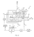
- FIG. 2 is a schematic diagram of an embodiment of an exemplary dual mode pump compensator, in a normal mode, that may be included in the system of FIG. 1 ;
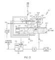
- FIG. 3 is a schematic diagram of the exemplary dual mode pump compensator depicted in FIG. 2 , but in a shutdown mode.
- FIG. 1 a simplified schematic diagram of one embodiment of a fuel delivery and control system for a gas turbine engine, such as a turbofan jet aircraft engine, is depicted.
- the system 100 includes a fuel source 102, one or more pumps 104, 106, metering valve 108, a pump compensator 110 and an engine controller 150.
- the fuel source 102 which is preferably implemented as one or more tanks, stores fuel that is to be supplied to a plurality of fuel loads 112 (e.g. 112-1, 112-2, 112-3, ... 112-N).
- the number and type of fuel loads may vary, and may include one or more of a gas turbine engine combustor zone and associated nozzles112-1, a motive flow valve and regulator 112-2, one or more variable geometry actuators 112-3, and one or more bleed valves 112-4, just to name a few.
- a supply line 114 is coupled to the fuel source 102 and, via the just-mentioned pumps 104, 106, delivers the fuel to the fuel loads 112. It is noted that the supply line 114 is, for convenience, depicted and described with a single reference numeral. However, it will be appreciated that the system 100 is implemented using separate sections of piping, though a single section is certainly not prohibited.
- a shutoff valve 122 is disposed in the supply line 114 downstream of the pumps 104, 106. The shutoff valve 122 is movable between an open position and a closed position. In the depicted embodiment, the shutoff valve 122 is a hydraulically operated valve.
- the depicted shutoff valve 122 includes a position control pressure port 123 that is at least selectively in fluid communication with a fluid pressure source.
- the shutoff valve 122 is responsive to the fluid pressure at the position control pressure port 123 to move between the open and closed positions. It will be appreciated that in some embodiments the shutoff valve may also function to ensure there is a minimum system pressure magnitude in portions of the supply line 114, and to shut when the pressure falls below this minimum pressure magnitude.
- Each of the one or more pumps 104, 106 is positioned in flow-series in the supply line 114 and take a suction on the fuel source 102.
- two engine-driven pumps are used and include a boost pump 104, such as a relatively low horsepower centrifugal pump, and a high pressure pump 106, such as a variable displacement piston pump.
- the boost pump 104 takes a suction directly on the fuel source 102 and provides sufficient suction head for the high pressure pump 106.
- the high pressure pump 106 a preferred embodiment of which will now be described, then supplies the fuel at a relatively high pressure to the remainder of the supply line 114.
- the system 100 may additionally include a low pressure pump with the fuel tank(s) 102 to supply fuel to the boost pump 104.
- the high pressure pump 106 is preferably a variable displacement piston pump, and includes an adjustable hanger 116, and a hanger actuator 118.
- a variable displacement piston pump can be adjusted to increase or decrease the amount of fuel it supplies.
- the adjustable hanger 116, or swash plate as it is sometimes referred to is coupled to a plurality of non-illustrated pistons that are disposed, one each, in a plurality of non-illustrated cylinders.
- the stroke of the pistons in the cylinders, and thus the flow rate of the variable displacement piston pump 106 is varied by varying the position of the adjustable hanger 116.
- the position of the adjustable hanger 116 is varied by the hanger actuator 118.
- the hanger actuator 118 includes a pump control pressure inlet port 119 that is in fluid communication with, and thus receives pump control fluid from, the pump compensator 110. As will be described in more detail further below, the hanger actuator 118 is responsive to fluid pressure variations of the pump control fluid to move the adjustable hanger 116.
- the metering valve 108 is positioned in flow-series in the supply line 114 downstream of the variable displacement piston pump 106 and upstream of the shutoff valve 122.
- the metering valve 108 includes an inlet port 124, and outlet port 126, a variable area flow orifice 128, and an actuator 132.
- a portion of the fuel in the supply line 114 flows into the metering valve inlet port 124, through the variable area flow orifice 128, and out the metering valve outlet port 126.
- the metering valve actuator 132 is used to adjust the position of the metering valve 108, and thus the area of the variable area flow orifice 128.
- the metering valve 108 is a hydraulically-operated valve and the metering valve actuator 132 is an electro-hydraulic servo valve (EHSV) that is used to adjust the position of the metering valve 108 by controlling the flow of operational hydraulic fluid to the metering valve 108.
- EHSV electro-hydraulic servo valve
- the metering valve 108 and actuator 132 may each be implemented using other types of devices.
- the metering valve 108 could be an electrically operated valve.
- the metering valve actuator 132 may not be used, or it could be implemented as an independent controller.
- fuel flow rate to the engine combustor 112-1 is controlled by adjusting the position of the metering valve 108, and thus the area of the variable area flow orifice 128, via the metering valve actuator 132.
- a position sensor 134 is coupled to the metering valve 108.
- the position sensor 134 is configured to sense metering valve position and supply a metering valve position signal to the engine controller 150.
- the position of the metering valve 108 is directly related to the area of the variable area flow orifice 128, which is directly related to the fuel flow rate to the combustor 112-1.
- the position sensor 134 is preferably a dual channel linear variable differential transformer (LVDT), but could be any one of numerous position sensing devices known in the art.
- the position sensor 134 could be a rotary variable differential transformer (RVDT), an optical sensor, a potentiometer sensor, or the like.
- the pump compensator 110 is in fluid communication with the hanger actuator 118 and, as previously noted, supplies pump control fluid to the hanger actuator 118.
- the pump compensator 110 includes at least a pump control pressure outlet port 136 and a mode control pressure port 138.
- the pump control pressure outlet port 136 is in fluid communication with, and supplies the pump control fluid to, the hanger actuator pump control pressure inlet port 119.
- the mode control pressure port 138 is coupled to a non-illustrated fluid pressure source. Though not depicted in FIG. 1 , it will be appreciated that in some embodiments the mode control pressure port 138 and the shutoff valve position control pressure port 123 may be coupled to the same fluid pressure source.
- the pump compensator 110 which is preferably a dual mode device, is configured to be responsive to fluid pressure at the mode control pressure port 138 to operate in either a normal mode or a shutdown mode.
- the overall operation of the pump compensator 110 in each of these modes will first be described.
- the pump compensator 110 controls the fluid pressure of the pump control fluid supplied to the hanger actuator 118 such the variable displacement pump supplies fuel at a rate to maintain a constant differential pressure across the metering valve 108. It is generally known that engine nozzle backpressure varies as a function of the metered flow rate through the metering valve 108 to the combustor 112-1. Hence, in order to maintain the differential pressure across the metering valve 108, the discharge pressure of the variable displacement piston pump 106 also varies as a function of metered flow.
- the pump controller 110 in the normal mode, controls the fluid pressure of the pump control fluid supplied to the hanger actuator 118 such that the variable displacement piston pump 106 is controlled in accordance with a variable flow/variable discharge pressure scheme.
- the pump compensator 110 controls the fluid pressure of the pump control fluid supplied to the hanger actuator 118 such that the variable displacement piston pump 106 is controlled in accordance with a variable flow/constant discharge pressure scheme.
- the pump compensator 110 is placed in the shutdown mode when the configuration of the system 100 is such that the variable displacement piston pump 106 only needs to supply an amount of flow sufficient to make up for internal losses and, if needed or desired, to maintain sufficient pressure to supply fuel to one or more of the other fuel loads 112-2, 112-3, 112-4, . . . 112-N.
- a particular embodiment of the pump compensator 110 that is configured to implement this functionality will be described in greater detail further below. However, for completeness of system description, the engine controller 150 will first be briefly discussed.
- the engine controller 150 which may be implemented as a Full Authority Digital Engine Controller (FADEC) or other electronic engine controller (EEC), controls the system 100 to operate in a normal mode or a shutdown mode. To do so, the engine controller 150 receives various input signals and, in response, controls the position of the shutoff valve 122 and the fuel flow rate to the combustor 112-1 accordingly. In particular, in the normal mode the engine controller 150 is responsive to an input from, for example, non-illustrated thrust command equipment in a non-illustrated aircraft cockpit, and to the metering valve position signal.
- FADEC Full Authority Digital Engine Controller
- EEC electronic engine controller
- the engine controller 150 may additionally receive one or more other signals, and may additionally supply control signals to one or more non-illustrated control devices associated with one or more of the other fuel loads 112-2, 112-3, 112-4, ... 112-N.
- the engine controller 150 in response to the signals it receives, causes the fluid pressure at the shutoff valve position control pressure port 123 to be of a magnitude that causes the shutoff valve 122 to move to the open position.
- the engine controller 150 further causes the fluid pressure at the pump compensator mode control pressure port 138 to be of a magnitude that causes the pump compensator 110 to be configured to operate in its normal mode.
- the engine controller 150 additionally supplies appropriate fuel flow commands to the metering valve actuator 132.
- the metering valve actuator 132 adjusts the area of the metering valve variable area flow orifice 128 to obtain the desired flow rate to the combustor 112-1.
- the pump compensator 110 when configured to operate in its normal mode, it controls the position of the adjustable hanger 116 so that a constant ⁇ P is maintained across the metering valve 108.
- K 1 is a constant
- the flow rate, W F is controlled by adjusting the area, A, of the metering valve variable area flow orifice 128.
- the engine controller 150 receives a suitable shutdown signal from, for example, non-illustrated equipment in the non-illustrated cockpit.
- the engine controller 150 causes the fluid pressure at the shutoff valve position control pressure port 123 to be of a magnitude that causes the shutoff valve 122 to move to the closed position.
- the engine controller 150 also causes the fluid pressure at the pump compensator mode control pressure port 138 to be of a magnitude that causes the pump compensator 110 to be configured to operate in its shutdown mode.
- the variable displacement piston pump 106 at least initially, is still being driven so that fuel may be supplied to one or more of the other fuel loads 112-2, 112-3, 112-4, ... 112-N.
- the pump compensator 110 in its shutdown mode, controls the fluid pressure of the pump control fluid supplied to the hanger actuator 118 such that the variable displacement piston pump 106 is controlled in accordance with a variable flow/constant discharge pressure scheme.
- the pump compensator 110 includes a mode control valve 202 and a compensator valve 204 and, in addition to the pump control pressure outlet port 136 and the mode control pressure port 138, further includes a reference pressure port 206, a first control pressure port 208, and a second control pressure port 212.
- the mode control valve 202 is responsive to fluid pressure at the mode control pressure port 138 to move between a normal mode position, which is the position depicted in FIG. 2 , and a shutdown mode position, which is the position depicted in FIG. 3 .
- the compensator valve 204 is in fluid communication with the mode control valve 202 and controls the fluid pressure of the pump control fluid at the pump control pressure outlet port 136, and thus at the hanger actuator pump control pressure inlet port 119, and concomitantly the control scheme of the variable displacement piston pump 106, based on the position of the mode control valve 202. Specifically, when the mode control valve 202 is in the normal mode position, the variable displacement piston pump 106 is controlled in accordance with the variable flow/variable discharge pressure scheme, and when the mode control valve 202 is in the shutdown mode position, the variable displacement piston pump 106 is controlled in accordance with the variable flow/constant discharge pressure scheme.
- the depicted mode control valve 202 includes a valve body 214, a shuttle valve 216, and a shuttle valve bias spring 215.
- the valve body 214 includes a first fluid outlet port 218, a second fluid outlet port 222, and an inner surface 223 that defines a shuttle valve chamber 227.
- the shuttle valve chamber 226 is in fluid communication with the mode control pressure port 138, the reference pressure port 206, the first control pressure port 208, the second control pressure port 212, the first fluid outlet port 218, and the second fluid outlet port 222.
- the shuttle valve 216 is movably disposed within the shuttle valve chamber 227 and is biased toward the normal mode position via a force supplied thereto from the shuttle valve bias spring 215.
- the shuttle valve 216 responsive to the fluid pressure (P MODE ) at the mode control pressure port 138, and the force supplied from the shuttle valve bias spring 215, to move between the normal mode position and the shutdown mode position.
- the first control pressure port 208 and the second control pressure port 212 are in fluid communication with the first fluid outlet port 218 and the second fluid outlet port 222, respectively.
- the shutdown mode position which is the position depicted in FIG. 3
- the reference pressure port 206 is in fluid communication with the first and second fluid outlet ports 218, 222.
- the compensator valve 204 includes a valve body 224, a valve element 226, and a compensator valve bias spring 225.
- the valve body 224 includes a first section 228 and a second section 232 of differing cross sectional areas.
- the first section 228 has a first cross sectional area
- the second section 232 has a second cross sectional area that is less than the first cross sectional area.
- the valve body first section 228 is in fluid communication with the mode control valve first and second fluid outlets 218, 222 via, for example, suitable conduits 234, 236, and the valve body second section 232 is in fluid communication with the pump control pressure outlet port 136, the reference pressure port 206, and the first control pressure port 208.
- the valve element 226 is movably disposed within the valve body 224, and includes a first spool 238 and a second spool 242.
- the first spool 238, which has a first diameter, is disposed within the valve body first section 228 and divides the valve body first section 228 into two chambers - a first chamber 244 and a second chamber 246.
- the first chamber 244 is in fluid communication with the mode control valve first fluid outlet 218, and the second fluid chamber 246 is in fluid communication with the mode control valve second fluid outlet 222.
- the first spool 238 additionally includes a spring side 248 and a doughnut side 252. The spring side 248 is exposed to fluid pressure in the second chamber 246, and is engaged by the compensator valve bias spring 225.
- the compensator valve bias spring 225 is disposed in the second chamber 246 and supplies a bias force to the valve element 226 that urges the valve element 226 toward the left, as viewed in FIGS. 2 and 3 .
- the second spool 242 which has a second diameter that is less than the first diameter of the, is disposed within the valve body second section 232.
- the second spool 242 is coupled to, and is fluidly isolated from, the first spool 238, and more specifically is coupled to the doughnut side 252 of the first spool.
- valve element 226 is responsive to the bias force supplied from the compensator valve bias spring 225, the fluid pressure at the first control pressure port 208, and the fluid pressures in the first and second chambers 244, 246, to cause the pump compensator 110 operate in either the normal mode or the shutdown mode.
- the pump compensator 110 is disposed within the system 100 such that the reference pressure source corresponds to the inlet of the variable displacement piston pump 106.
- the reference pressure port 206 is in fluid communication with, and the fluid pressure (P 0 ) at the reference port 206 corresponds to the pressure at, the inlet of the variable displacement piston pump 106.
- the first pump control pressure port 208 is in fluid communication with the metering valve inlet port 124
- the second pump control pressure port 212 is in fluid communication with the metering valve outlet port 126.
- the fluid pressure (P 1 ) at the first pump control pressure port 208 (e.g., the metering valve inlet port 124) is continuously supplied to the compensator valve first spool 238, and the fluid pressure (P 0 ) of the reference pressure source (e.g., the variable displacement piston pump inlet) is continuously supplied to the valve body second section 232 of the compensator valve 204.
- the fluid pressures in the compensator valve first and second chambers 244, 246 are set based on the position of the shuttle valve 216.
- the fluid pressure (P 1 ) at the first pump control pressure port 208 e.g., variable displacement piston pump discharge pressure
- the fluid pressure (P 2 ) at the second pump control pressure port 212 e.g., the metering valve discharge pressure
- the pressure differential (P 1 - P 2 ) between the first and second pump control pressure ports acts across the full diameter of the first spool 238, which maximizes the head regulation sensitivity in the normal mode.
- the compensator valve 204 controls the fluid pressure (P X ) of the pump control fluid such that the pressure differential between the first and second pump control pressure ports (P 1 - P 2 ), or more specifically the pressure differential across the metering valve 108, is maintained constant (or at least substantially constant).
- the shutoff valve 122 is moved to the closed position, stopping fuel flow from the metering valve to the combustor 112-1.
- the fluid pressure (P MODE ) at the mode control pressure port 138 is increased to at least a magnitude that allows the shuttle valve 216 to move, against the bias force of the shuttle valve bias spring 215, to the shutdown mode position.
- the fluid pressure (P 0 ) of the reference pressure source e.g., the variable displacement piston pump inlet
- the reference pressure (P 0 ) acts on both the spring side 248 and the doughnut side 252 of the first spool 238.
- the compensator valve 204 controls the fluid pressure (P X ) of the pump control fluid such that the pump discharge pressure (P 1 ) is maintained constant (or at least substantially constant).
- the pump discharge pressure (P 1 ) in the shutoff mode may be preset by appropriate selection of the compensator valve diameters. This allows for the provision, if desired, of sufficient internal system pressure to one or more of the other fuel loads 112-2, 112-3, 112-4, ... 112-N.
- variable displacement piston pump 106 will de-stroke to only provide the needed flow to maintain its discharge pressure (P1).
Landscapes
- Engineering & Computer Science (AREA)
- Mechanical Engineering (AREA)
- General Engineering & Computer Science (AREA)
- Chemical & Material Sciences (AREA)
- Combustion & Propulsion (AREA)
- Computer Hardware Design (AREA)
- Fluid-Pressure Circuits (AREA)
Applications Claiming Priority (2)
| Application Number | Priority Date | Filing Date | Title |
|---|---|---|---|
| US95271707P | 2007-07-30 | 2007-07-30 | |
| US11/943,755 US8128378B2 (en) | 2007-07-30 | 2007-11-21 | Dual mode compensation for variable displacement pump fluid metering system |
Publications (3)
| Publication Number | Publication Date |
|---|---|
| EP2025933A2 true EP2025933A2 (de) | 2009-02-18 |
| EP2025933A3 EP2025933A3 (de) | 2018-03-28 |
| EP2025933B1 EP2025933B1 (de) | 2019-03-27 |
Family
ID=39967890
Family Applications (1)
| Application Number | Title | Priority Date | Filing Date |
|---|---|---|---|
| EP08161293.9A Ceased EP2025933B1 (de) | 2007-07-30 | 2008-07-28 | Dualmodus-Kompensierung für ein Pumpmesssystem mit variabler Verdrängung |
Country Status (1)
| Country | Link |
|---|---|
| EP (1) | EP2025933B1 (de) |
Cited By (2)
| Publication number | Priority date | Publication date | Assignee | Title |
|---|---|---|---|---|
| CN109138043A (zh) * | 2017-06-27 | 2019-01-04 | 苏州赟羽机电科技有限公司 | 一种高效给水设备 |
| US11674455B2 (en) | 2021-03-26 | 2023-06-13 | Hamilton Sundstrand Corporation | Variable displacement pump with active bypass feedback control |
Family Cites Families (5)
| Publication number | Priority date | Publication date | Assignee | Title |
|---|---|---|---|---|
| GB1163712A (en) * | 1966-02-10 | 1969-09-10 | Lucas Industries Ltd | Fuel Systems for Gas Turbine Engines. |
| US3596467A (en) * | 1969-10-31 | 1971-08-03 | Avco Corp | Integrated fuel control system for a gas turbine engine |
| GB9910074D0 (en) * | 1999-04-30 | 1999-06-30 | Lucas Ind Plc | Fuel control system and valve therefor |
| JP2002147351A (ja) * | 2000-11-10 | 2002-05-22 | Toyota Industries Corp | 容量可変型圧縮機の制御装置 |
| GB0214467D0 (en) * | 2002-06-24 | 2002-08-07 | Delphi Tech Inc | Control valve for air conditioning compressor |
-
2008
- 2008-07-28 EP EP08161293.9A patent/EP2025933B1/de not_active Ceased
Cited By (2)
| Publication number | Priority date | Publication date | Assignee | Title |
|---|---|---|---|---|
| CN109138043A (zh) * | 2017-06-27 | 2019-01-04 | 苏州赟羽机电科技有限公司 | 一种高效给水设备 |
| US11674455B2 (en) | 2021-03-26 | 2023-06-13 | Hamilton Sundstrand Corporation | Variable displacement pump with active bypass feedback control |
Also Published As
| Publication number | Publication date |
|---|---|
| EP2025933A3 (de) | 2018-03-28 |
| EP2025933B1 (de) | 2019-03-27 |
Similar Documents
| Publication | Publication Date | Title |
|---|---|---|
| US8128378B2 (en) | Dual mode compensation for variable displacement pump fluid metering system | |
| US9234464B2 (en) | Fuel metering system electrically servoed metering pump | |
| US9353688B2 (en) | High pressure, multiple metering zone gas turbine engine fuel supply system | |
| EP4063654B1 (de) | Variable verdrängerpumpe mit aktiver umgehungsrückkopplungssteuerung | |
| US7836676B2 (en) | Fuel metering valve back-up position control system | |
| JP5666604B2 (ja) | 航空エンジンのための燃料供給回路 | |
| JP5539525B2 (ja) | 航空エンジンのための燃料供給回路 | |
| US7966995B2 (en) | Dual level pressurization control based on fuel flow to one or more gas turbine engine secondary fuel loads | |
| EP2025901A2 (de) | Kraftstoffzumessystem mit minimaler Wärmezuführung | |
| US11788476B1 (en) | Fluid system with variable pump discharge pressure and method | |
| EP1344917B1 (de) | Kraftstoffzufuhrregelsystem | |
| EP2428662A2 (de) | Brennstoffsteuerungsystem für Gasturbinentriebwerk | |
| US9140190B2 (en) | Gas turbine engine fuel metering valve adapted to selectively receive fuel flow increase/decrease commands from the engine control and from the back-up fuel control | |
| EP3034839B1 (de) | Mittel und anordnung für einen kraftstoffvereisungsschutz | |
| EP2025933B1 (de) | Dualmodus-Kompensierung für ein Pumpmesssystem mit variabler Verdrängung | |
| EP4124735B1 (de) | Steuern eines gasförmigen brennstoffstroms in einem flugzeugmotor | |
| EP4382747B1 (de) | Verstellpumpe mit strömungsabgabe an verschiedene systeme mit unterschiedlichen druckplänen | |
| US20240350722A1 (en) | Electrically direct controlled variable displacement pumps | |
| US12454950B2 (en) | Direct control for variable displacement pumps using a bypass valve and a minimum pressure shutoff valve | |
| US12398720B2 (en) | Direct controlled variable displacement valves with dual set point pressure relief | |
| EP1735529A1 (de) | Verfahren und vorrichtung, das bzw. die mehrere drucksignale in einem brennstoffsystem erzeugen |
Legal Events
| Date | Code | Title | Description |
|---|---|---|---|
| PUAI | Public reference made under article 153(3) epc to a published international application that has entered the european phase |
Free format text: ORIGINAL CODE: 0009012 |
|
| 17P | Request for examination filed |
Effective date: 20080728 |
|
| AK | Designated contracting states |
Kind code of ref document: A2 Designated state(s): AT BE BG CH CY CZ DE DK EE ES FI FR GB GR HR HU IE IS IT LI LT LU LV MC MT NL NO PL PT RO SE SI SK TR |
|
| AX | Request for extension of the european patent |
Extension state: AL BA MK RS |
|
| RAP1 | Party data changed (applicant data changed or rights of an application transferred) |
Owner name: HONEYWELL INTERNATIONAL INC. |
|
| PUAL | Search report despatched |
Free format text: ORIGINAL CODE: 0009013 |
|
| AK | Designated contracting states |
Kind code of ref document: A3 Designated state(s): AT BE BG CH CY CZ DE DK EE ES FI FR GB GR HR HU IE IS IT LI LT LU LV MC MT NL NO PL PT RO SE SI SK TR |
|
| AX | Request for extension of the european patent |
Extension state: AL BA MK RS |
|
| RIC1 | Information provided on ipc code assigned before grant |
Ipc: F02C 9/26 20060101ALI20180222BHEP Ipc: F04B 49/06 20060101ALI20180222BHEP Ipc: F04B 1/29 20060101AFI20180222BHEP |
|
| 17Q | First examination report despatched |
Effective date: 20180315 |
|
| GRAP | Despatch of communication of intention to grant a patent |
Free format text: ORIGINAL CODE: EPIDOSNIGR1 |
|
| INTG | Intention to grant announced |
Effective date: 20180726 |
|
| GRAJ | Information related to disapproval of communication of intention to grant by the applicant or resumption of examination proceedings by the epo deleted |
Free format text: ORIGINAL CODE: EPIDOSDIGR1 |
|
| GRAP | Despatch of communication of intention to grant a patent |
Free format text: ORIGINAL CODE: EPIDOSNIGR1 |
|
| INTC | Intention to grant announced (deleted) | ||
| INTG | Intention to grant announced |
Effective date: 20180912 |
|
| GRAS | Grant fee paid |
Free format text: ORIGINAL CODE: EPIDOSNIGR3 |
|
| AKX | Designation fees paid |
Designated state(s): DE FR GB |
|
| AXX | Extension fees paid |
Extension state: RS Extension state: AL Extension state: MK Extension state: BA |
|
| GRAA | (expected) grant |
Free format text: ORIGINAL CODE: 0009210 |
|
| AK | Designated contracting states |
Kind code of ref document: B1 Designated state(s): DE FR GB |
|
| REG | Reference to a national code |
Ref country code: GB Ref legal event code: FG4D |
|
| REG | Reference to a national code |
Ref country code: DE Ref legal event code: R096 Ref document number: 602008059483 Country of ref document: DE |
|
| REG | Reference to a national code |
Ref country code: DE Ref legal event code: R097 Ref document number: 602008059483 Country of ref document: DE |
|
| PLBE | No opposition filed within time limit |
Free format text: ORIGINAL CODE: 0009261 |
|
| STAA | Information on the status of an ep patent application or granted ep patent |
Free format text: STATUS: NO OPPOSITION FILED WITHIN TIME LIMIT |
|
| 26N | No opposition filed |
Effective date: 20200103 |
|
| PGFP | Annual fee paid to national office [announced via postgrant information from national office to epo] |
Ref country code: FR Payment date: 20210726 Year of fee payment: 14 |
|
| PGFP | Annual fee paid to national office [announced via postgrant information from national office to epo] |
Ref country code: DE Payment date: 20210729 Year of fee payment: 14 Ref country code: GB Payment date: 20210726 Year of fee payment: 14 |
|
| REG | Reference to a national code |
Ref country code: DE Ref legal event code: R119 Ref document number: 602008059483 Country of ref document: DE |
|
| GBPC | Gb: european patent ceased through non-payment of renewal fee |
Effective date: 20220728 |
|
| PG25 | Lapsed in a contracting state [announced via postgrant information from national office to epo] |
Ref country code: FR Free format text: LAPSE BECAUSE OF NON-PAYMENT OF DUE FEES Effective date: 20220731 |
|
| PG25 | Lapsed in a contracting state [announced via postgrant information from national office to epo] |
Ref country code: GB Free format text: LAPSE BECAUSE OF NON-PAYMENT OF DUE FEES Effective date: 20220728 Ref country code: DE Free format text: LAPSE BECAUSE OF NON-PAYMENT OF DUE FEES Effective date: 20230201 |
|
| P01 | Opt-out of the competence of the unified patent court (upc) registered |
Effective date: 20230525 |