EP2026011A2 - Dispositif d'appareil ménager - Google Patents
Dispositif d'appareil ménager Download PDFInfo
- Publication number
- EP2026011A2 EP2026011A2 EP08104912A EP08104912A EP2026011A2 EP 2026011 A2 EP2026011 A2 EP 2026011A2 EP 08104912 A EP08104912 A EP 08104912A EP 08104912 A EP08104912 A EP 08104912A EP 2026011 A2 EP2026011 A2 EP 2026011A2
- Authority
- EP
- European Patent Office
- Prior art keywords
- domestic appliance
- skirt body
- area
- arrangement according
- actuating element
- Prior art date
- Legal status (The legal status is an assumption and is not a legal conclusion. Google has not performed a legal analysis and makes no representation as to the accuracy of the status listed.)
- Withdrawn
Links
- 238000009434 installation Methods 0.000 claims abstract description 8
- 230000001681 protective effect Effects 0.000 claims description 8
- 229910052751 metal Inorganic materials 0.000 claims description 6
- 239000002184 metal Substances 0.000 claims description 6
- 230000015572 biosynthetic process Effects 0.000 claims description 4
- 238000000465 moulding Methods 0.000 abstract 1
- 230000006870 function Effects 0.000 description 13
- 238000010411 cooking Methods 0.000 description 5
- 238000004519 manufacturing process Methods 0.000 description 5
- 229920001296 polysiloxane Polymers 0.000 description 5
- 238000004080 punching Methods 0.000 description 4
- 238000005755 formation reaction Methods 0.000 description 3
- 229920005372 Plexiglas® Polymers 0.000 description 2
- 238000010276 construction Methods 0.000 description 2
- 239000000463 material Substances 0.000 description 2
- 239000004926 polymethyl methacrylate Substances 0.000 description 2
- 238000000926 separation method Methods 0.000 description 2
- 230000003213 activating effect Effects 0.000 description 1
- 230000001419 dependent effect Effects 0.000 description 1
- 238000006073 displacement reaction Methods 0.000 description 1
- 238000009432 framing Methods 0.000 description 1
- 239000011521 glass Substances 0.000 description 1
- 238000000034 method Methods 0.000 description 1
- 238000012986 modification Methods 0.000 description 1
- 230000004048 modification Effects 0.000 description 1
- 229910000510 noble metal Inorganic materials 0.000 description 1
- 239000010970 precious metal Substances 0.000 description 1
- 238000003825 pressing Methods 0.000 description 1
- 230000008569 process Effects 0.000 description 1
- 230000009993 protective function Effects 0.000 description 1
- 238000007493 shaping process Methods 0.000 description 1
- 210000002105 tongue Anatomy 0.000 description 1
- 230000007704 transition Effects 0.000 description 1
- 230000001960 triggered effect Effects 0.000 description 1
- 230000000007 visual effect Effects 0.000 description 1
- 238000005406 washing Methods 0.000 description 1
Images

Classifications
-
- F—MECHANICAL ENGINEERING; LIGHTING; HEATING; WEAPONS; BLASTING
- F24—HEATING; RANGES; VENTILATING
- F24C—DOMESTIC STOVES OR RANGES ; DETAILS OF DOMESTIC STOVES OR RANGES, OF GENERAL APPLICATION
- F24C7/00—Stoves or ranges heated by electric energy
- F24C7/08—Arrangement or mounting of control or safety devices
- F24C7/082—Arrangement or mounting of control or safety devices on ranges, e.g. control panels, illumination
-
- H—ELECTRICITY
- H03—ELECTRONIC CIRCUITRY
- H03K—PULSE TECHNIQUE
- H03K17/00—Electronic switching or gating, i.e. not by contact-making and –breaking
- H03K17/94—Electronic switching or gating, i.e. not by contact-making and –breaking characterised by the way in which the control signals are generated
- H03K17/96—Touch switches
- H03K2017/9602—Touch switches characterised by the type or shape of the sensing electrodes
Definitions
- the invention is based on a domestic appliance arrangement according to the preamble of claim 1.
- the object of the invention is in particular to provide a generic arrangement with improved properties in terms of ease of manufacture and an attractive design.
- the invention is based on a household appliance arrangement with a skirt body, which forms a home appliance face, and at least one actuating element.
- the skirt body has at least one formation which forms the actuating element.
- the actuating element is advantageously formed integrally with the skirt body, whereby components and space can be saved and a robust mounting of the actuating element can be achieved.
- a "skirt body" is to be understood as meaning, in particular, a household appliance component which forms a domestic appliance viewing surface and has a covering function for covering domestic appliance interior parts.
- the skirt body has at least one base region which has the function of a control panel for a household appliance control device.
- the basic area is fixed relative to a household appliance body, in particular a household appliance functional space formed by the household appliance body, such as a cooking chamber, a laundry room, a cold room, a washing room, etc.
- the actuator is preferably movable relative to the base area and it can be switched on or off by means of a movement of the actuating element home appliance function and / or it can be set a home appliance operating parameters.
- the skirt body is arranged on a domestic appliance front side, wherein a home appliance visual surface formed by the apron body corresponds to a domestic appliance front surface.
- the apron body may, for example, have a base area, which is designed as a household appliance front panel.
- the base area advantageously extends in one piece over at least a substantial part, ie over at least 50%, preferably over at least 75%, of an extension, ie the length or the width, of the appliance front.
- an area can be recessed from the basic area, which area is provided for a display unit and / or for further actuating elements.
- a "home appliance viewing surface” should be understood to mean, in particular, a surface that is visible to an end user of a household appliance under proper conditions of use.
- the skirt body has a base portion and the operating member is formed as a ridge continuing from the base portion, whereby a particularly simple construction and an actuator with a short stroke can be achieved.
- a resilient mounting of the actuating element can be achieved in a particularly simple design.
- At least a portion of the skirt body is recessed to form the actuating element, whereby a material-saving production can be achieved.
- a simple manufacturing method can be achieved if the portion is cut out by means of a punching out of the skirt body.
- a slot unit is recessed from the skirt body to form the actuator, whereby a particularly compact construction can be achieved.
- a particularly simple shaping of the actuating element can be achieved if the slot unit has at least two parallel longitudinal slots.
- a "Longitudinal slit" is to be understood in this context, in particular a slot with a longitudinal direction, wherein the extension is formed in the longitudinal direction advantageously longer than a threefold and particularly advantageously longer than a fivefold of the width thereof.
- An advantageous mobility of the actuating element can be achieved if the slots are formed open in one direction.
- the skirt body forms at least two actuators and the slot unit has a slot separating the actuators, whereby a domestic appliance assembly having a group of adjacent actuators can be made particularly easily.
- a further space saving can advantageously be achieved if the recessed portion adjoins a recessed for a display unit display area.
- the skirt body extends in a home appliance basic installation position over at least a substantial part of a domestic appliance front in the vertical direction, whereby a saving of other components and assembly steps and a robust design of the domestic appliance arrangement can be advantageously achieved.
- a "home appliance basic installation position” is to be understood in particular a position which is present under normal or prescribed conditions of use in the case of an application of a household appliance in which the domestic appliance arrangement is used.
- the terms “horizontal,” “vertical,” “top,” “bottom,” “side,” etc. refer to the orientation of the home appliance assembly in a home appliance basic installation position.
- at least one substantial part is to be understood as meaning, in particular, at least 50%, advantageously at least 75%, and preferably at least 90%.
- the skirt body has at least one partial area, which is designed as a frame unit for at least partially surrounding a household appliance door area, whereby an additional protective function of the apron body can be achieved.
- the skirt body preferably adjoins at least three sides of the household appliance door area.
- the skirt body may have a U-shape.
- the actuating element has a width which is at least one thirtieth of the skirt body width.
- the domestic appliance arrangement has a light signal unit with a luminous area, which is assigned to the actuating element, whereby the ease of use can be further increased.
- the luminous area is formed as an elongated area extending over at least a substantial part of an actuator edge.
- the oblong luminous area extends parallel to the actuating element edge in particular over at least 50%, advantageously over at least 75% and particularly preferably over at least 90% of the extension of the actuating element edge.
- the domestic appliance arrangement has a protective unit for protecting the actuating element, such as e.g. a protective frame, which forms the luminous area, whereby components and space can be advantageously saved.
- This protection unit is preferably made of a translucent material, e.g. Plexiglas or translucent silicone, made.
- the domestic appliance arrangement can have a light source unit which is provided for backlighting of the protective unit.
- a robust and durable home appliance arrangement can also be achieved if the skirt body is made of metal.
- An optically responsive skirt body may be further achieved if the skirt body is made of at least one precious metal.
- the skirt body forms at least two actuating elements and has a receiving area for receiving an operating means, which is arranged between the actuating elements, whereby further functionalities of the domestic appliance arrangement can be achieved in a compact manner.
- the receiving area "between" two actuating elements is arranged, if there is at least one point of the first actuating element and a straight segment connecting a point of the second operating member, which intersects the receiving area at at least one point located between the points.
- FIG. 1 shows a cooking appliance, as an oven, trained domestic appliance 10 in a front view.
- the household appliance 10 is in FIG. 1 shown in its basic installation position, in which it is supported on a horizontal shelf 12.
- the domestic appliance 10 has a domestic appliance front side 14, which is aligned in the basic installation position essentially in the vertical direction 16 and faces a person operating the domestic appliance 10 under conditions which conform to the regulations.
- the domestic appliance 10 has a domestic appliance arrangement 18, which is arranged on the appliance front side 14.
- the home appliance assembly 18 includes a skirt body 20 that forms a home appliance face 22 visible to an end user of the home appliance 10 that is vertically aligned in the home appliance home position.
- the apron body 20 is fastened by means not shown fastening elements to a household appliance body, which forms a domestic appliance function space, as in the case under consideration a cooking chamber.
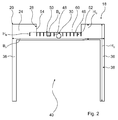
- the description of the apron body 20 also refers to FIG. 2 showing the apron body 20 separated from the home appliance body in a front view.
- the skirt body 20 has a base region 24, which serves as a household appliance front panel.
- the base region 24 extends horizontally in the home appliance basic installation position Direction across the width of the household appliance front side 14.
- the base region 24 has a covering function as a household appliance front panel and, in particular, covers electrical or electronic components of the domestic appliance 10, such as switching elements, in the horizontal direction.
- the skirt body 20 has a bulge which forms a display area 28 provided for a display unit 26.
- the display area 28 is recessed from the skirt body 20, by means of a separation process, such as in particular by means of a punch-out.
- the display area 28 is formed in the vertical direction 16 open at the top and with respect to the width of the home appliance front side 14 in this home appliance front side 14 centered.
- the display area 28 is encompassed by the skirt body 20.
- the display unit 26 is designed as an LCD display, which is used to display symbols and / or plain text displays.
- the apron body 20 further forms a receiving area 30, which is circular and serves to receive an operating means 32 designed as a toggle handle of an actuating unit 34 of the domestic appliance 10.
- the apron body 20 is formed as a one-piece body made of sheet metal, in particular a sheet metal produced with at least one noble metal, and has a U-shape.
- the skirt body 20 has two elongated, in the vertical direction 16 extending portions 36, each of which adjoin the base region 24 in one piece.
- the partial areas 36 and the base area 24 form in cooperation a partial area of the apron body 20, which is designed as a frame unit 38 for framing a household appliance door area 40.
- a household appliance door 42 In the domestic appliance door area 40 is a household appliance door 42 which is actuated by a door handle 44 by an operator to a pivoting movement.
- the household appliance door 42 in its closed position closes a domestic appliance function room, which is formed in the example considered as a cooking chamber.
- the home appliance door 42 is provided with a home appliance window having a transparent glass through which an operator can observe a home appliance function operation performed in the home appliance function room, such as a cooking operation in particular.
- the domestic appliance door area 40 which is delimited by the skirt body 20, is designed to be open downwards in the vertical direction 16.
- the base region 24, which is arranged in the vertical direction 16 above the domestic appliance door region 40 forms the upper limit of the domestic appliance door region 40 and the vertical partial regions 36, which are aligned parallel to one another, form the lateral boundaries of the domestic appliance door region 40 arranged on both sides of the household appliance door area 40.
- the home appliance door area 40 is hereby by means of the base area 24 and the vertical portions 36 partially framed.
- the apron body 20 extends in the vertical direction 16 in the region of the lateral edges of the appliance front side 14 over the height of the domestic appliance front side 14.
- the partial regions 36 extend from the base region 24 straight to the lower edge of the domestic appliance front side 14.
- the domestic appliance 10th For example, as a dishwasher, the formation of the apron body 20 as a over the entire appliance front side 14 extending component is conceivable.
- the domestic appliance arrangement 18 furthermore has a plurality of actuating elements 46 which form the actuating unit 34 with the operating means 32.
- the actuators 46 are each configured as keys that are provided to activate a home appliance function by an end user.
- the keys each have a different function assigned.
- function symbols are provided, which are respectively attached to the front surface of one of the actuators 46, e.g. by means of a printing process.
- the actuating elements 46 are distributed in two groups, which are arranged in the horizontal direction on both sides of the receiving area 30 and in each case in a horizontal row.
- the receiving area 30 is arranged in the horizontal direction between the groups of actuating elements 46.
- the actuating elements 46 and the receiving area 30 are located in the vertical direction 16 below the display area 28.
- the actuators 46 are each formed as a formations of the apron body 20.
- the actuating elements 46 are each designed as a web extending from the base region 24 vertically upwards.
- the actuators 46 are integrally formed with the base portion 24.
- the front surface of the base region 24 and the front surface of one of the actuators 46 each form a continuous transition. Alternatively, it is conceivable that these front surfaces form a step.
- the actuating elements 46 are separated in a horizontal direction from the base region 24 or by a directly adjacent actuating element 46 by means of a slot 48 of a slot unit 50.
- the slot unit 50 in this case has a plurality of slots 48.
- slots 48 are each formed as a longitudinal slot which extends from the base portion 24 in the vertical direction 16 upwards. Further, the slots 48 of the slot unit 50 are aligned parallel to each other. The slots 48 are also formed in the vertical direction 16 open at the top, so that formed by this slot 48 space between two adjacent actuators 46 or between an actuating element 46 and the base area 24 adjoins the display area 28 provided for the display unit 26.
- the slot unit 50 corresponds to a portion 52, which is recessed in the manufacture of the appliance assembly 18 from the skirt body 20 to form the actuating elements 46.
- the display area 28, the slot unit 50 and possibly the receiving area 30 by means of a separation process, by means of a punching, from the skirt body 20, which is formed as a sheet metal piece, recessed.
- the punching out of the display area 28 can take place separately from the punching-out operation to form the slot unit 50, or the display area 28 and the slot unit 50 can be recessed in a same punching operation.
- the portion 52 serving to form the operating members 46 adjoins the display portion 28.
- the base region 24 has a rectilinear edge 54 which forms a lateral boundary of the display region 28, this rectilinear edge 54 continuing continuously in the vertical direction 16 downwards as an edge delimiting a slot 48.
- the serving as domestic appliance front panel base region 24 has in the vertical direction 16, starting from the upper edge of the skirt body 20 to the upper limit of the domestic appliance door area 40, a height H G on.
- the display area 28 extends in the vertical direction 16 over a distance which is half H G / 2 of the height H G.
- the actuating elements 46 and the receiving area 30 are arranged in the lower half of the household appliance front panel formed by the base area 24.
- the lower half of the base portion 24 is below an imaginary line extending horizontally and arranged at a distance of H G / 2 from the upper edge of the skirt body 20.
- the trained as metal tongues actuators 46 have an extension in the vertical direction 16, which corresponds to a height H B of H G / 4.
- a contiguous portion of the base portion 24 is arranged, which has a height of H G / 4.
- the apron body 20 has a skirt body height H S in the region of its lateral edges, ie an extent in the vertical direction 16 which corresponds to a height of a multiple, in particular a six times, height H G.
- the length, ie the vertical extension, of the partial regions 36 corresponds to five times the height H G.
- the skirt body 20, namely the base region 24, has a skirt body width B S , ie an extension in the horizontal direction.
- the display area 28 has a Extension in the horizontal direction, which is a length of at least 40% of the skirt body width B S.
- the actuators 46 together with the receiving area 30 form an assembly that extends the length of the display area 28.
- the actuating elements 46 embodied as keys have a width B B , ie an extent in the horizontal direction which corresponds at least to a length of B S / 30. In particular, the actuating elements 46 have a width B B of at least 22 mm.
- the home appliance assembly 18 is further provided with a light signal unit 56.
- This has a plurality of luminous areas 58, wherein a luminous area 58 is in each case assigned to a different actuating element 46.
- These luminous regions 58 which are respectively arranged in the vertical direction 16 above one of the actuating elements 46, are each formed as an elongate region, which has a main direction of extension in the horizontal direction.
- a luminous area 58 extends parallel to the upper actuating element edge 60 of an actuating element 46.
- a luminous area 58 has a longitudinal extent B L which corresponds to the width B B of the associated actuating element 46.
- the domestic appliance arrangement 18 has a light source unit and a control unit which, in cooperation with the light source unit, is provided to illuminate the lighting area 58 corresponding to the actuating element 46 when an actuating element 46 is actuated.
- the luminous regions 58 are each fixed relative to the base region 24. An arrangement of the luminous regions 58 on the actuators 46 is also conceivable.
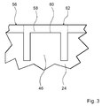
- FIG. 3 can be seen, in which a detailed view of an actuating element 46 is shown, the luminous areas 58 are formed by a protective unit 62, which serves to protect the actuating elements 46.
- the protection unit 62 forms a protective frame, which frames the actuators 46 partially.
- a luminous area 58 corresponds to a partial area of the protective unit 62, which is arranged above the upper actuating element edge 60. It is conceivable that the entire partial area, which partially frames the actuating element 46, is designed as a luminous area.
- the luminous regions 58 may be formed by a component made of light-transmissive material, such as a component made of Plexiglas.
- the protection unit can have a protective body made of silicone, preferably a translucent silicone.
- a protective body made of silicone, preferably a translucent silicone.
- it may be a silicone strip along the corresponding upper actuator edge 60 and / or silicone strips are backlit along the lateral actuator edges of the light source unit.
- the actuating elements 46 which are each designed as a web and hereby related to their base with the base region 24 are formed as spring elements. Upon actuation, ie, upon depression of an actuator 46, starting from an initial position, it automatically returns to its initial position upon release. When triggered by the pressing movement of the actuating element 46 relative to the base region 24, the actuating element 46 is arranged behind the actuator 46 and not shown in the figures switch is operated, which is in operative connection with an electrical control unit, not shown, for switching on the corresponding domestic appliance function. Due to the small displacement of the actuators 46, the switches are each designed as Kurzhubschalter.
Landscapes
- Engineering & Computer Science (AREA)
- Chemical & Material Sciences (AREA)
- Combustion & Propulsion (AREA)
- Mechanical Engineering (AREA)
- General Engineering & Computer Science (AREA)
- Induction Heating Cooking Devices (AREA)
- Closures For Containers (AREA)
Applications Claiming Priority (1)
| Application Number | Priority Date | Filing Date | Title |
|---|---|---|---|
| DE102007037301A DE102007037301A1 (de) | 2007-08-07 | 2007-08-07 | Hausgeräteanordnung |
Publications (2)
| Publication Number | Publication Date |
|---|---|
| EP2026011A2 true EP2026011A2 (fr) | 2009-02-18 |
| EP2026011A3 EP2026011A3 (fr) | 2010-10-06 |
Family
ID=40011279
Family Applications (1)
| Application Number | Title | Priority Date | Filing Date |
|---|---|---|---|
| EP08104912A Withdrawn EP2026011A3 (fr) | 2007-08-07 | 2008-07-29 | Dispositif d'appareil ménager |
Country Status (2)
| Country | Link |
|---|---|
| EP (1) | EP2026011A3 (fr) |
| DE (1) | DE102007037301A1 (fr) |
Citations (5)
| Publication number | Priority date | Publication date | Assignee | Title |
|---|---|---|---|---|
| EP0872818A2 (fr) * | 1997-04-17 | 1998-10-21 | GRUNDIG Aktiengesellschaft | Dispositif de commande à distance à clavier illuminé |
| DE19805301A1 (de) * | 1998-02-10 | 1999-08-12 | Bosch Siemens Hausgeraete | Vorrichtung mit mindestens einem Sensorschalter |
| EP1569057A2 (fr) * | 2004-02-25 | 2005-08-31 | BSH Bosch und Siemens Hausgeräte GmbH | Champ d'un panneau de commande pour appareil électroménager à commande par programme |
| DE102004058478A1 (de) * | 2004-11-23 | 2006-05-24 | E.G.O. Elektro-Gerätebau GmbH | Bedienvorrichtung für ein Elektrogerät |
| EP1662207A1 (fr) * | 2004-11-30 | 2006-05-31 | Diehl AKO Stiftung & Co. KG | Dispositiv de contrôle pour un appareil ménager |
Family Cites Families (7)
| Publication number | Priority date | Publication date | Assignee | Title |
|---|---|---|---|---|
| DK123737B (da) * | 1969-12-01 | 1972-07-24 | Bang & Olufsen As | Betjeningspanel og fremgangsmåde til fremstilling af samme. |
| ES166467Y (es) | 1971-02-26 | 1971-10-16 | Ulgor, S. C. I. | Estructura principal para aparatos domesticos. |
| CH569234A5 (fr) * | 1972-09-07 | 1975-11-14 | Bauknecht Gmbh G | |
| US6019982A (en) * | 1994-08-26 | 2000-02-01 | The Administrators Of The Tulane Educational Fund | Mutant enterotoxin effective as a non-toxic oral adjuvant |
| DE29519714U1 (de) * | 1995-12-12 | 1996-02-01 | Electrolux AG, Zürich | Bedienungselement für ein Haushaltgerät |
| ATE205373T1 (de) * | 1996-01-15 | 2001-09-15 | Miele & Cie | Getränkebereiter |
| DE19649047C2 (de) * | 1996-11-27 | 1998-09-10 | Juno Kuechentech Electrolux | Haushaltsgerät mit einer Bedienblende, die mit von vorne nicht sichtbaren Befestigungselementen befestigt ist |
-
2007
- 2007-08-07 DE DE102007037301A patent/DE102007037301A1/de not_active Withdrawn
-
2008
- 2008-07-29 EP EP08104912A patent/EP2026011A3/fr not_active Withdrawn
Patent Citations (5)
| Publication number | Priority date | Publication date | Assignee | Title |
|---|---|---|---|---|
| EP0872818A2 (fr) * | 1997-04-17 | 1998-10-21 | GRUNDIG Aktiengesellschaft | Dispositif de commande à distance à clavier illuminé |
| DE19805301A1 (de) * | 1998-02-10 | 1999-08-12 | Bosch Siemens Hausgeraete | Vorrichtung mit mindestens einem Sensorschalter |
| EP1569057A2 (fr) * | 2004-02-25 | 2005-08-31 | BSH Bosch und Siemens Hausgeräte GmbH | Champ d'un panneau de commande pour appareil électroménager à commande par programme |
| DE102004058478A1 (de) * | 2004-11-23 | 2006-05-24 | E.G.O. Elektro-Gerätebau GmbH | Bedienvorrichtung für ein Elektrogerät |
| EP1662207A1 (fr) * | 2004-11-30 | 2006-05-31 | Diehl AKO Stiftung & Co. KG | Dispositiv de contrôle pour un appareil ménager |
Non-Patent Citations (1)
| Title |
|---|
| "A passion for Sound Design , Beogram4004", 31 December 1980 (1980-12-31), Retrieved from the Internet <URL:http://beophile.com/?page_id=731> [retrieved on 20110913] * |
Also Published As
| Publication number | Publication date |
|---|---|
| DE102007037301A1 (de) | 2009-02-12 |
| EP2026011A3 (fr) | 2010-10-06 |
Similar Documents
| Publication | Publication Date | Title |
|---|---|---|
| EP1137860B1 (fr) | Poignee exterieure notamment de portiere de vehicule comprenant une poignee en forme d'etrier dotee d'un actionneur par pression integre | |
| DE10051171B4 (de) | Wippschalter | |
| DE10020172B4 (de) | Griff für Fahrzeugtüren mit Entriegelung durch Mikroschalter | |
| DE8816238U1 (de) | Tastschalter | |
| DE102012200812A1 (de) | Kältegerät mit in der Tür angeordneter Benutzerschnittstelle | |
| EP1662207B1 (fr) | Dispositiv de contrôle pour un appareil ménager | |
| EP2206132B1 (fr) | Actionneur | |
| DE102014214218B4 (de) | Bedieneinheit für ein elektrisches Gerät, insbesondere für eine Fahrzeugkomponente | |
| DE102006024994B3 (de) | Elektronischer Schalter | |
| DE10316934B4 (de) | Tastenblock zum Einsetzen in eine Bedienfläche eines Haushaltsgerätes | |
| DE202010002712U1 (de) | Profilsystem für eine Türanlage und daraus hergestellte Türanlage | |
| DE102016100795B4 (de) | Wippschalter mit beweglichen Lichtschächten | |
| WO2012168326A1 (fr) | Unité de commande pour un composant de véhicule | |
| EP2026011A2 (fr) | Dispositif d'appareil ménager | |
| DE10309516B3 (de) | Tastenblock mit Federgeometrie | |
| DE102004056603A1 (de) | Kunststoffanbauteil | |
| DE10307536B4 (de) | Blende mit rechteckigem Tastenblock und Verfahren zu dessen Herstellung | |
| EP3145082A1 (fr) | Dispositif de commande d'un appareil electrique, appareil electrique et procede de fabrication d'un tel dispositif de commande | |
| EP1423035B1 (fr) | Appareil electromenager pour la cuisine | |
| DE3917637A1 (de) | Mehrfachtastschalter | |
| DE102005053928B4 (de) | Bedienelement für Haushaltsgerät | |
| DE10349592B4 (de) | Tastenblock zum Einsetzen in eine Blende und Montageanordnung eines Tastenblocks an einer Blende | |
| EP0593077B1 (fr) | Interrupteur d'appareil | |
| DE202005018658U1 (de) | Elektrische Schaltervorrichtung | |
| DE60125284T2 (de) | Druckschalter |
Legal Events
| Date | Code | Title | Description |
|---|---|---|---|
| PUAI | Public reference made under article 153(3) epc to a published international application that has entered the european phase |
Free format text: ORIGINAL CODE: 0009012 |
|
| AK | Designated contracting states |
Kind code of ref document: A2 Designated state(s): AT BE BG CH CY CZ DE DK EE ES FI FR GB GR HR HU IE IS IT LI LT LU LV MC MT NL NO PL PT RO SE SI SK TR |
|
| AX | Request for extension of the european patent |
Extension state: AL BA MK RS |
|
| PUAL | Search report despatched |
Free format text: ORIGINAL CODE: 0009013 |
|
| AK | Designated contracting states |
Kind code of ref document: A3 Designated state(s): AT BE BG CH CY CZ DE DK EE ES FI FR GB GR HR HU IE IS IT LI LT LU LV MC MT NL NO PL PT RO SE SI SK TR |
|
| AX | Request for extension of the european patent |
Extension state: AL BA MK RS |
|
| 17P | Request for examination filed |
Effective date: 20110406 |
|
| AKX | Designation fees paid |
Designated state(s): AT BE BG CH CY CZ DE DK EE ES FI FR GB GR HR HU IE IS IT LI LT LU LV MC MT NL NO PL PT RO SE SI SK TR |
|
| 17Q | First examination report despatched |
Effective date: 20110923 |
|
| RAP1 | Party data changed (applicant data changed or rights of an application transferred) |
Owner name: BSH HAUSGERAETE GMBH |
|
| GRAP | Despatch of communication of intention to grant a patent |
Free format text: ORIGINAL CODE: EPIDOSNIGR1 |
|
| RIC1 | Information provided on ipc code assigned before grant |
Ipc: H03K 17/96 20060101ALI20181001BHEP Ipc: F24C 7/08 20060101AFI20181001BHEP |
|
| INTG | Intention to grant announced |
Effective date: 20181030 |
|
| STAA | Information on the status of an ep patent application or granted ep patent |
Free format text: STATUS: THE APPLICATION IS DEEMED TO BE WITHDRAWN |
|
| 18D | Application deemed to be withdrawn |
Effective date: 20190312 |