EP2026012A2 - Appareil ménager doté d'un recouvrement - Google Patents
Appareil ménager doté d'un recouvrement Download PDFInfo
- Publication number
- EP2026012A2 EP2026012A2 EP08104913A EP08104913A EP2026012A2 EP 2026012 A2 EP2026012 A2 EP 2026012A2 EP 08104913 A EP08104913 A EP 08104913A EP 08104913 A EP08104913 A EP 08104913A EP 2026012 A2 EP2026012 A2 EP 2026012A2
- Authority
- EP
- European Patent Office
- Prior art keywords
- cover
- household appliance
- domestic appliance
- door
- oven
- Prior art date
- Legal status (The legal status is an assumption and is not a legal conclusion. Google has not performed a legal analysis and makes no representation as to the accuracy of the status listed.)
- Withdrawn
Links
Images
Classifications
-
- F—MECHANICAL ENGINEERING; LIGHTING; HEATING; WEAPONS; BLASTING
- F24—HEATING; RANGES; VENTILATING
- F24C—DOMESTIC STOVES OR RANGES ; DETAILS OF DOMESTIC STOVES OR RANGES, OF GENERAL APPLICATION
- F24C7/00—Stoves or ranges heated by electric energy
- F24C7/08—Arrangement or mounting of control or safety devices
- F24C7/082—Arrangement or mounting of control or safety devices on ranges, e.g. control panels, illumination
-
- F—MECHANICAL ENGINEERING; LIGHTING; HEATING; WEAPONS; BLASTING
- F24—HEATING; RANGES; VENTILATING
- F24C—DOMESTIC STOVES OR RANGES ; DETAILS OF DOMESTIC STOVES OR RANGES, OF GENERAL APPLICATION
- F24C15/00—Details
- F24C15/02—Doors specially adapted for stoves or ranges
-
- F—MECHANICAL ENGINEERING; LIGHTING; HEATING; WEAPONS; BLASTING
- F24—HEATING; RANGES; VENTILATING
- F24C—DOMESTIC STOVES OR RANGES ; DETAILS OF DOMESTIC STOVES OR RANGES, OF GENERAL APPLICATION
- F24C15/00—Details
- F24C15/36—Protective guards, e.g. for preventing access to heated parts
Definitions
- the present invention relates to a household appliance with at least one functional element for operating the same and a cover for an optional covering of the functional element.
- Household appliances usually have functional elements to support the operation. Widely used are, for example, displays, in particular displays, and operating elements such as pushbuttons, rotary knobs, in particular the gags of a baking oven, or touchscreens.
- a cooking area with a toggle switch panel As a safety device, a flap is mounted above the switch panel via a hinge, which projects in the unfolded state over the height of the cooking surface upwards. When folded down, the switch panel can be covered by the flap.
- a disadvantage of this teaching is that the flap in the unfolded state of an operator may interfere with the way, such as in the handling of cookware on the hob. Furthermore, this optically conspicuous supernatant can also be perceived as aesthetically disadvantageous.
- the DE 26 02 835 C3 shows a household appliance with a control panel having control panel.
- a protective plate is mounted above the switch panel and can be pivoted relative to the switch panel. If the switch panel to be made accessible, the protective plate is pivoted about the storage upwards, in a depth direction of the Domestic appliance inserted above the switch panel extending space and there releasably latched.
- a disadvantage of this teaching is that the pivoting, insertion, latching and tripping again requires a rather complex mechanism. Next, the required opening of the room for inserting the protective plate can make the front of the appliance visually restless.
- the invention is therefore an object of the invention to provide a household appliance with a cover which, in a simple structure, a covering of a functional element allows, in which the cover does not interfere with movements of an operator and which allows alternative optical designs.
- the invention is based on the finding that this object can be achieved by a cover is mounted so that it can be offset along the surface of the household appliance.
- the object is achieved by a household appliance with at least one functional element for operating the household appliance and a cover for an optional covering at least one of the functional elements.
- the household appliance is characterized in that the cover along a surface of the household appliance at least between a rest position in which the cover at least partially covers the at least one functional element, and an operating position in which the at least one functional element is exposed and another part of the surface of the Household appliance is covered by the cover is displaceable.
- functional elements are in particular indicators and operating elements.
- the functional elements may be, for example, buttons, knobs or displays.
- the cover completely covers the functional element in one position. If the domestic appliance has a plurality of functional elements located close to one another in comparison to the extent of the domestic appliance, for example in the case of a switch panel or control bar with gags and a display, it is preferred if the cover completely covers all of these functional elements in the rest position. For reasons of linguistic simplicity, reference is here made to a plurality of functional elements.
- an element is referred to, which is preferably flat, for example as a plate, designed and preferably made of opaque material.
- the cover may for example consist of metal, in particular stainless steel.
- In the rest position is or are the functional elements partially or completely hidden by the cover. In this position, access and thus actuation of the functional elements are not possible.
- the functional elements are in the rest position of the cover thus protected against accidental operation, for example, in the cleaning of the surface of the household appliance, where the cover is provided. Also, fouling of the functional elements in the rest position of the cover can be prevented by this.
- the view of the functional elements is not possible and the visual appearance of the surface of the household appliance and thus the entire household appliance receives a quieter visual appearance.
- the surface on which the cover is provided is preferably the front of the household appliance, that is, the user of the household appliance side facing.
- the cover In the operating position, the cover is offset from the rest position. In the operating position, the one or more functional elements are free and can be operated by the user of the household appliance. the other part of the cover conceals in this position another part of the surface of the household appliance. As a result, a protrusion or rising of the cover is prevented for example on the upper edge of the front of the household appliance and the user of the household appliance thus not disturbed by the cover.
- the cover according to the invention between the rest position and the operating position along the surface of the household appliance is displaceable, changes on the one hand the visual impression of the household appliance between the two positions only by the visible in the operating position functional elements.
- the cover does not change their visual appearance.
- veneers which are folded upwards relative to the household appliance and in which the inside of the veneer thus becomes visible in the operating state
- the appearance of the displaceable cover used according to the invention in the rest position and the operating position is the same.
- the storage of the cover can be easily configured.
- the holder of the cover is referred to in the context of this invention, which holds the cover in the two positions and the movement between these two positions.
- a further advantage of the invention is that the surface of the household appliance can be made visually very quiet, since the cover itself can be optically quiet and possibly existing optically conspicuous structures on the body of the household appliance can be covered.
- the cover and the storage by means of which the cover is connected to the household appliance, cover are
- the storage of the cover allows only translational movements of the cover.
- a translational movement is a movement in which each point of the cover is moved in the same direction by the same amount.
- a plurality of translatory movements for displacing the cover be performed.
- the cover can be first removed by a certain amount from the surface of the household appliance, then be offset parallel to the surface and moved again to the surface.
- a translational movement can be realized with simpler mechanisms. As a result, the structure of the household appliance is simplified.
- the cover is displaceable along the surface of the household appliance between the rest position and the operating position.
- the displacement of the cover is advantageous because the required support or storage of the cover can be made particularly simple and in particular may consist of simple rails.
- the cover is mounted on the surface of the household appliance.
- the storage of the cover can be glued, for example, on the surface of the household appliance, welded or otherwise secured to the surface.
- the mechanism for displacing the cover for example the rails, is received in the cover.
- This embodiment has the advantage that the surface of the household appliance does not have to be changed. In particular, no recesses or cavities for receiving the storage of the cover or for the cover itself are required.
- the surface is, for example, a surface made of glass or other sensitive materials, it is advantageous to apply the bearing of the cover to the latter, since processing the Surface is difficult.
- the storage of the cover may be designed so that the cover rests directly on the surface during both the displacement and in the rest and the operating position; but it can also be provided a distance between the cover and the surface, in particular during the displacement. Since the storage itself is optionally covered by the cover, the impression can be conveyed that the cover floating in a displacement in front of the surface of the household appliance.
- the cover is mounted on the surface of the household appliance on a part of the surface which is separated from the part of the surface which has the at least one functional element.
- the cover may be mounted on the door and the functional elements may be provided on the part defining the frame of the door.
- This arrangement has the advantage that the cover in the rest position, in which it covers the functional elements, also obscures the transition from one part of the surface to the other part of the surface.
- a gap provided between the door and a switch panel can be concealed by the cover.
- the visual appearance of the household appliance is further improved and created in particular a quieter appearance.
- the cover is part of a multi-part covering device.
- the cover is offset relative to a further part of the cover, in particular moved.
- This embodiment is particularly suitable for cases in which the covering covers a large area.
- the cover is a frame or forms part of a frame-shaped covering device.
- the cover or the covering device can cover the largest possible area with relatively little weight.
- the frame for example, cover the gap formed between the door and the door frame. If the covering device constitutes a frame, then, for example, the lower web of the frame and the lateral webs of the frame can be fixedly connected to the surface, in particular the door, and the upper web can be moved, in particular displaced, relative to these fixed webs.
- the household appliance is an oven.
- the control and display elements are usually above the opening of the oven muffle, which is closed by a door.
- the functional elements can be blinded together with the gap between the control bar and the door.
- controls for other household appliances such as located above the oven hotplate that can be integrated in the control bar on the front of the oven can be covered with the cover of the invention.
- an oven can be created with a quiet front view in the unused state.
- a provision of the controls, for example on the top of the door, as is possible with other household appliances, such as a dishwasher, is not possible due to the temperatures in the oven and thus on the oven door.
- the cover is preferably a frame or is part of a frame-shaped covering.
- the cover should be possible to check the condition of the food in the oven, the insight into the oven muffle without having to open the oven door. This can be easily accomplished using a frame.
- a sight glass may be provided in the opening of the frame.
- the storage of the cover, which is located behind the cover be additionally protected against contamination.
- the household appliance according to the invention preferably has functional elements which lie at least in a rest position in the plane of the strip or panel in which they are provided. For example, so-called touchscreens are used. But the use of retractable rotary knob is possible. By not protruding the functional elements out of the plane of the bar when not in use, the cover can easily be brought to the rest position in this position. In this embodiment, the cover can be easily brought by moving from the operating position to the rest position.
- the cover is mounted so that it by pivoting or lifting from the surface on which the cover is mounted, such a distance from the surface that it can be passed over the functional elements, without damaging them.
- the cover in the region in which it covers the functional elements preferably designed hollow, that is, has a functional elements facing the cavity.
- the cover can also be configured for other functions on the household appliance.
- a contact may be provided on the cover, which when connected to a surface provided further contact, leads to the interruption of the power supply.
- the display in the rest position of the cover is no longer visible through the cover and leading to the display power can be turned off to further reduce the energy consumption of the household appliance.
- the cover in particular, when it is attached to a door of a household appliance, at the same time serve to open the door.
- the cover itself can be configured as a handle, or have a handle.
- the handle can also facilitate the manual movement of the cover.
- a locking of the cover in the operating position or in the rest position by the user it is advantageous if a locking of the cover in the operating position or in the rest position by the user must be solved before the cover can be moved to the rest position. As a result, accidental movement or slippage of the cover when opening the door can be avoided.
- the cover can also serve, for example, for the additional closing or holding of a door of the domestic appliance on which it is provided, in the closed position.
- the cover preferably has a closure element.
- the cover may have a flange on its rear side, which engages in a corresponding groove on the surface of the household appliance.
- the groove may be provided on the sides of a control panel, and the flange may extend inwardly from the sides of the cover.
- the flange engages behind the front of the control bar and prevents opening of the door of the household appliance as long as the cover is in the rest position.
- the household appliance may for example also be a microwave and the like.
- the control bar is usually provided laterally from the door and the cover is made horizontally displaceable, in particular displaceable in these cases.
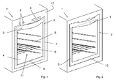
- FIG. 1 shows in perspective the front side 1 of a baking oven according to the invention.
- a baking oven door 11 is arranged below the functional elements 2, 3, a baking oven door 11 is arranged.
- a viewing window 4 is provided through which the insight into the interior of the oven, in particular in the oven muffle, is made possible.
- the oven door 11 is a drawer door, which allows horizontal access to access the interior of the oven.
- a cover in the form of an opaque frame 7 is applied on the oven door 11.
- the frame 7 has a width and height which are greater than the width and height of the oven door 11.
- a formed between the oven door 11 and the oven door 11 surrounding part of the front side 1 of the oven gap 8 (dashed line) is through the cover 7 hidden.
- the cover 7 are sized so that they in the in FIG. 1 shown position of the cover 7, the lower part of the gap 8 between the oven door 11 and further front 12 is not or only slightly covered.
- the lower part of the front side for example by means of a base offset to the rear (not shown) so as not to hinder the pivoting of the oven door 11 to open.
- the upper horizontally extending portion 9 of the frame 7 is curved in the illustrated embodiment to the outside, so that an operator can easily behind this and serve this section as a handle 9 for opening and closing the oven door 11 but also for moving the cover or the frame 7 can.
- the frame 7 is vertically displaceable on the oven door 11 applied. By an upward pulling an operator on the handle 9, the frame 7 moves upward. In the FIG. 1 shown position represents the operating position in which the controls 2 and the display 3 are accessible or visible.
- FIG. 2 shows the front 1 FIG. 1 with the upwardly shifted frame 7, that is in the rest position.
- the gag (2) and the display (3) are hidden here by the frame 7.
- the controls 2 and the display 3 can still be seen.
- the top of the handle 9 has a horizontally extending conclusion (not shown), through which the distance formed by the curvature of the handle 9 to the front side 1 of the oven is closed upwards.
- the upper horizontally extending portion 9 or handle 9 and the under horizontally extending portion 10 of the frame 7 are designed wide enough in their vertical, in order to conceal the gap 8 in this upwardly displaced position, the rest position.
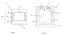
- FIG. 3 shows schematically a front view of a oven door 11 of a baking oven according to the invention.
- the cover 7 according to the invention is not shown to allow the view of the storage 35 for holding and guiding the cover 7.
- the oven door 11 has a frame-shaped, opaque enclosure 31 and a viewing window 4 surrounded by the enclosure 31.
- the holder 35 has two rails 33 and four locking devices 34.
- a guided in the rails 33 cover 7 can be moved (in a known per se and therefore not shown) slightly up and down. In its upper and lower end position, the cover 7 can be fixed or held by the locking means 34 until the cover 7 is moved by the user or the locking device 34 is released by the user.
- FIG. 4 shows like that Figures 1 and 2 a front side 1 of a baking oven according to the invention.
- a two-part frame 71, 72 hidden. Both parts of the frame 71, 72 are close to the body of the oven, that is on the front side 1 at.
- the frame 71, 72 conceals a gap surrounding a oven door 11 (not shown).
- a window 4 of the oven door 11 allows a view into the interior of the oven.
- Above the frame 71, 72 retractable toggle 2 and a flush mounted display 3 are shown.
- the frame 71, 72 has a relative to the oven door 11 stationary part 71, which is designed as "U" on both sides and below the window 4 is located.
- the upper horizontally extending portion 72 of the frame 71, 72 can be moved upwards starting from the operating position shown here and thus serves as a cover according to the invention.
- This rest position of the upper portion 72 of the frame 71, 72 is indicated schematically in the figure by the dotted line. In this rest position, the upper part 72 covers the toggle 2 to be sunk due to the close contact of the frame 71, 72 and the display 3.
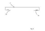
- FIG. 5 schematically a sectional view of a cover 7 is shown.
- the cover 7 consists here of a bent sheet metal, which has two inwardly bent flanges 73 on the back.
- the flanges 73 can engage in grooves in the sides of a control bar, in which the controls 2 and the display 3 are provided, and thus avoid opening the oven door in the rest position of the cover 7.
- the schematically indicated contacts can interact with contacts or switches on the control bar and, for example, interrupt the power supply to the display 3.
- the shape of the cover may deviate from the shown frame shape and, for example, have the shape of a strip.
- the home appliance can be designed so that the cover in no position protrudes from the body, so that a corresponding possibly hindering and visually conspicuous projection is avoided.
- the cover itself optically quiet can be and they also cover visually striking structures on the body, so home appliances can be created, which have an overall optically calm impression. It can thus be created a new appearance for household appliances, especially ovens and high design differentiation can be achieved.
- the household appliance according to the invention integrates more easily into various kitchen environments because it is defined in terms of design as a whole, in contrast to conventional household appliances, which produce a brand differentiation mainly on individual equipment details such as size of applications, handles and gag. In addition, a child safety is given by the covering of the controls.
Landscapes
- Engineering & Computer Science (AREA)
- Chemical & Material Sciences (AREA)
- Combustion & Propulsion (AREA)
- Mechanical Engineering (AREA)
- General Engineering & Computer Science (AREA)
- Electric Ovens (AREA)
- Switch Cases, Indication, And Locking (AREA)
Applications Claiming Priority (1)
| Application Number | Priority Date | Filing Date | Title |
|---|---|---|---|
| DE200710037518 DE102007037518A1 (de) | 2007-08-08 | 2007-08-08 | Haushaltsgerät mit Abdeckung |
Publications (2)
| Publication Number | Publication Date |
|---|---|
| EP2026012A2 true EP2026012A2 (fr) | 2009-02-18 |
| EP2026012A3 EP2026012A3 (fr) | 2011-03-23 |
Family
ID=39847008
Family Applications (1)
| Application Number | Title | Priority Date | Filing Date |
|---|---|---|---|
| EP08104913A Withdrawn EP2026012A3 (fr) | 2007-08-08 | 2008-07-29 | Appareil ménager doté d'un recouvrement |
Country Status (2)
| Country | Link |
|---|---|
| EP (1) | EP2026012A3 (fr) |
| DE (1) | DE102007037518A1 (fr) |
Citations (2)
| Publication number | Priority date | Publication date | Assignee | Title |
|---|---|---|---|---|
| DE2602835C3 (de) | 1976-01-27 | 1980-09-18 | Licentia Patent-Verwaltungs-Gmbh, 6000 Frankfurt | Schalterblende mit Bedienungsorganen für Haushaltgeräte |
| DE8800720U1 (de) | 1988-01-22 | 1988-05-19 | Pichert, Horst, Prof. Dr.-Ing., 8000 München | Kochstelle mit Sicherheitseinrichtung |
Family Cites Families (4)
| Publication number | Priority date | Publication date | Assignee | Title |
|---|---|---|---|---|
| US3527200A (en) * | 1969-04-10 | 1970-09-08 | Eagle Range & Mfg Co | Range control panel assembly |
| ES295403Y (es) * | 1986-06-25 | 1987-11-01 | Martinez Sanchez Miguel | Barrera de proteccion para cocinas domesticas |
| IT229048Y1 (it) * | 1992-07-23 | 1998-06-24 | Zanussi Elettrodomestici | Lavastoviglie ad incasso con pannello di comando nascosto |
| DE102005028335A1 (de) * | 2005-06-18 | 2006-12-21 | Premark Feg L.L.C., Wilmington | Geschirrspülmaschine |
-
2007
- 2007-08-08 DE DE200710037518 patent/DE102007037518A1/de not_active Withdrawn
-
2008
- 2008-07-29 EP EP08104913A patent/EP2026012A3/fr not_active Withdrawn
Patent Citations (2)
| Publication number | Priority date | Publication date | Assignee | Title |
|---|---|---|---|---|
| DE2602835C3 (de) | 1976-01-27 | 1980-09-18 | Licentia Patent-Verwaltungs-Gmbh, 6000 Frankfurt | Schalterblende mit Bedienungsorganen für Haushaltgeräte |
| DE8800720U1 (de) | 1988-01-22 | 1988-05-19 | Pichert, Horst, Prof. Dr.-Ing., 8000 München | Kochstelle mit Sicherheitseinrichtung |
Also Published As
| Publication number | Publication date |
|---|---|
| DE102007037518A1 (de) | 2009-02-12 |
| EP2026012A3 (fr) | 2011-03-23 |
Similar Documents
| Publication | Publication Date | Title |
|---|---|---|
| DE10302797B4 (de) | Tür für ein Kältegerät und Kältegerät, umfassend eine Tür | |
| EP1027561B1 (fr) | Appareil menager a panneau frontal | |
| DE102009026659B4 (de) | Haushaltsgerät | |
| DE4009326A1 (de) | Antriebsmechanismus fuer einen einziehbaren, nach unten gerichteten abzug | |
| WO2013107663A1 (fr) | Appareil de froid à interface utilisateur installée dans la porte | |
| DE7711172U1 (de) | Herdtuerverriegelung | |
| DE102008043364A1 (de) | Hausgerätetür mit verfahrbarem Bügelgriff | |
| EP2182145B1 (fr) | Porte d'appareil ménager avec une poignée à branche | |
| EP1979681B1 (fr) | Agencement double d'appareils ménagers | |
| DE2921188C2 (de) | Anordnung einer Vorsatzplatte an einem Haushaltgerät | |
| DE102011007471A1 (de) | Bedienelement für ein Haushaltsgerät und Haushaltsgerät | |
| DE2921187C2 (de) | Anordnung einer Vorsatzplatte an einem Haushaltgerät | |
| EP2026012A2 (fr) | Appareil ménager doté d'un recouvrement | |
| DE202005018079U1 (de) | Bedienvorrichtung, insbesondere für Dunstabzugshaube und Dunstabzugshaube | |
| EP2397770A1 (fr) | Appareil de cuisson et procédé | |
| DE4331110C2 (de) | Schaltschrank mit einem Auszug | |
| EP3425284B1 (fr) | Appareil combiné pourvu de plaque de cuisson et de dispositif de hotte aspirante intégré à la plaque de cuisson et armoire de cuisine pourvue d'appareil combiné | |
| EP4185813A1 (fr) | Porte et dispositif de cuisson domestique | |
| EP2045534B1 (fr) | Four de cuisson | |
| DE2657746A1 (de) | Backofen, insbesondere einbaubackofen | |
| EP4477957B1 (fr) | Appareil de cuisson avec rails télescopiques | |
| DE102014224981A1 (de) | Frontpanel einer Dunstabzugshaube und Dunstabzugshaube | |
| EP4086546B1 (fr) | Récipient alimentaire doté d'un dispositif de climatisation à réglage spécifique entre une barquette et une pièce rapportée, ainsi qu'appareil frigorifique électroménager | |
| DE102008054593B4 (de) | Tür für ein Hausgerät und Hausgerät zur Zubereitung von Lebensmitteln mit einer derartigen Tür | |
| DE60117278T2 (de) | Vorrichtung für einen ofen zur verbesserung des einblicks in den ofenraum |
Legal Events
| Date | Code | Title | Description |
|---|---|---|---|
| PUAI | Public reference made under article 153(3) epc to a published international application that has entered the european phase |
Free format text: ORIGINAL CODE: 0009012 |
|
| AK | Designated contracting states |
Kind code of ref document: A2 Designated state(s): AT BE BG CH CY CZ DE DK EE ES FI FR GB GR HR HU IE IS IT LI LT LU LV MC MT NL NO PL PT RO SE SI SK TR |
|
| AX | Request for extension of the european patent |
Extension state: AL BA MK RS |
|
| PUAL | Search report despatched |
Free format text: ORIGINAL CODE: 0009013 |
|
| AK | Designated contracting states |
Kind code of ref document: A3 Designated state(s): AT BE BG CH CY CZ DE DK EE ES FI FR GB GR HR HU IE IS IT LI LT LU LV MC MT NL NO PL PT RO SE SI SK TR |
|
| AX | Request for extension of the european patent |
Extension state: AL BA MK RS |
|
| RIC1 | Information provided on ipc code assigned before grant |
Ipc: F24C 15/36 20060101ALI20110214BHEP Ipc: F24C 15/02 20060101ALI20110214BHEP Ipc: F24C 7/08 20060101AFI20081024BHEP |
|
| 17P | Request for examination filed |
Effective date: 20110923 |
|
| AKX | Designation fees paid |
Designated state(s): AT BE BG CH CY CZ DE DK EE ES FI FR GB GR HR HU IE IS IT LI LT LU LV MC MT NL NO PL PT RO SE SI SK TR |
|
| STAA | Information on the status of an ep patent application or granted ep patent |
Free format text: STATUS: THE APPLICATION HAS BEEN WITHDRAWN |
|
| 18W | Application withdrawn |
Effective date: 20131011 |