EP2026036A2 - Gyroskopisches Nordsuchsystem und -verfahren - Google Patents
Gyroskopisches Nordsuchsystem und -verfahren Download PDFInfo
- Publication number
- EP2026036A2 EP2026036A2 EP08161509A EP08161509A EP2026036A2 EP 2026036 A2 EP2026036 A2 EP 2026036A2 EP 08161509 A EP08161509 A EP 08161509A EP 08161509 A EP08161509 A EP 08161509A EP 2026036 A2 EP2026036 A2 EP 2026036A2
- Authority
- EP
- European Patent Office
- Prior art keywords
- signal
- sensor
- spinning device
- rate
- motor
- Prior art date
- Legal status (The legal status is an assumption and is not a legal conclusion. Google has not performed a legal analysis and makes no representation as to the accuracy of the status listed.)
- Granted
Links
Images
Classifications
-
- G—PHYSICS
- G01—MEASURING; TESTING
- G01C—MEASURING DISTANCES, LEVELS OR BEARINGS; SURVEYING; NAVIGATION; GYROSCOPIC INSTRUMENTS; PHOTOGRAMMETRY OR VIDEOGRAMMETRY
- G01C19/00—Gyroscopes; Turn-sensitive devices using vibrating masses; Turn-sensitive devices without moving masses; Measuring angular rate using gyroscopic effects
- G01C19/02—Rotary gyroscopes
- G01C19/34—Rotary gyroscopes for indicating a direction in the horizontal plane, e.g. directional gyroscopes
- G01C19/38—Rotary gyroscopes for indicating a direction in the horizontal plane, e.g. directional gyroscopes with north-seeking action by other than magnetic means, e.g. gyrocompasses using earth's rotation
Definitions
- ground-based navigation applications require directional knowledge. Examples of such applications include aiming/targeting techniques (e.g., for mortar/artillery), navigation of autonomous ground vehicles, and surveying techniques.
- aiming/targeting techniques e.g., for mortar/artillery
- navigation of autonomous ground vehicles e.g., for surveying techniques.
- surveying techniques e.g., surveying techniques.
- An important piece of information for use in ground-based navigation is knowledge of one's direction relative to the desired path of travel along the surface of the earth.
- Magnetic compasses require local calibrations to obtain even marginal accuracy.
- the GPS requires supporting electronics and cannot be used underground.
- the GPS also requires the user to be moving, and is susceptible to local area jamming.
- Conventional gyroscopes are typically too large and expensive given accuracy needs.
- North-seeking gyroscopes or gyrocompasses have been developed and are traditionally characterized by reference to a freely rotating gyroscope rotor having damped precession about its own axis of rotation which naturally aligns parallel to the earth's axis of rotation and perpendicular to the local centripetal acceleration vector due to the effective torque induced by the horizontal component of the coriolis force.
- a gyroscope having a large angular momentum vector influenced by a comparatively small torque will require significant time to align the angular momentum vector with the axis of rotation producing the torque.
- MEMS micro-electromechanical systems
- An exemplary MEMS sensor is disclosed in U.S. Patent No. 5,349,855 to Bernstein et al . (hereafter the "Bernstein patent”).
- MEMS gyroscopes have been used in low cost and performance applications especially automobiles.
- MEMS gyroscopes have also been used for inertial guidance but typically in conjunction with a GPS to offset gyro inaccuracies.
- MEMS technology typically refers to small mechanical elements micro-machined into a silicon substrate, which may also contain microcircuitry.
- the invention relates to a sensor system and method for determining a relative direction to true north.
- the system comprises at least one angular rate sensor, such as a MEMS sensor, which has an input axis and a rotation axis.
- the angular rate sensor comprises a motor drive structure, a motor signal output from the motor drive structure, a gyroscope, and a sensor rate output from the gyroscope for a sensor rate signal.
- a frequency divider is in operative communication with the motor signal output, and a spinning device is coupled to the angular rate sensor.
- a spinning device motor is coupled to the spinning device and is in operative communication with the frequency divider.
- the spinning device motor has an axis of rotation that is substantially perpendicular to the input axis of the angular rate sensor.
- the spinning device motor is configured to be driven by a periodic signal from the angular rate sensor.
- a position of the spinning device is synchronized to the periodic signal to generate a spinning device position signal.
- a phase detector is in operative communication with the spinning device motor and the sensor rate output. The relative direction to true north is determined from a phase differential between the spinning device position signal and the sensor rate signal.
- the present system and method can be used to find the relative direction of true north as defined by the earth's spin axis (not magnetic north).
- the present north seeking system includes an angular rate sensor device where the drive signal generation for a motor comes from the sensor device itself. No external drive signal generator is required as in prior devices.
- the present system and method solves the problem of synchronizing the rotation of the motor with the signal processing electronics.
- the relative direction to true north is determined from the phase differential between a sensor rate signal and the table rotation angle ⁇ of a table rotating at a constant rate ⁇ .
- This phase differential is discernible by many conventional techniques such as by use of a phase detector described herein or as described in the Watson patent.
- the present system can be implemented in a very small package size requiring relatively simple electronics/processing.
- a vibrating structure gyroscope such as a MEMS gyroscope can be used in the implementation.
- the present implementation eliminates rate bias from the MEMs gyroscope, and provides knowledge of true north assuming that one's approximate latitude is known.
- the system of the present invention can be used in many different applications where determining a direction of movement is important, such has navigation of various manned and unmanned vehicles, surveying, targeting, mining, and the like.
- the cost of the present system will be quite low relative to even compasses given that no scale factor calibration is required.
- Gyroscope bias calibration costs can also be substantially reduced given that accuracy is only driven by the change in bias over the time north seeking information is collected and not by the absolute bias accuracy.
- the present system and method are described as follows in the context of a MEMS device, the present invention is not limited to use in a MEMS device.
- the present system can be implemented using a ring laser gyroscope, or a fiber optic gyroscope (FOG).
- FOG fiber optic gyroscope
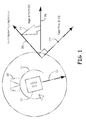
- FIG. 1 is a MEMS north seeking gyroscope vector diagram.
- a MEMS gyroscope (gyro) sensor 110 has an axis of rotation 112 from a spinning device such as a table or platform to which the gyroscope sensor is attached.
- the gyro sensor 110 rotates at a sensor motor frequency/K (K is arbitrary value), and has a gyroscope input axis 114 that is substantially coplanar with the table and substantially perpendicular to the axis of rotation 112.
- Rotation of gyro sensor 110 about axis of rotation 112 produces a sinusoidal sensor output signal 115 (earth rate sinusoid) with a magnitude peak corresponding to the orientation of input axis 114 of gyro sensor 110 when input axis 114 is most closely aligned with the earth's angular rate vector ( i.e., spin axis or geographic north).
- sinusoidal sensor output signal 115 earth rate sinusoid
- a local ground reference 116 is known relative to input axis 114. As discussed in further detail hereafter, the relative direction to true north is determined by measuring the phase difference between a table position signal and a sensor rate signal. A phase detector implementation can be used to measure the phase difference. This phase difference provides an angle to north 118. A north vector 120 can then be projected to level from ground reference 116 based on the angle to north 118. The north vector 120 forms a right angle with a table phase vector 122.
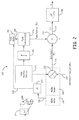
- FIG. 2 is a block diagram of a MEMS sensor north seeker system 200 according to one embodiment.
- the system 200 includes at least one MEMS sensor 210, which is coupled to a spinning device 213 such as a rotating table.
- the MEMS sensor 210 has a sensor input axis 211 that is substantially perpendicular to an axis of rotation 214 of the spinning device 213.
- the axis of rotation 214 should be relatively aligned to local level although a precision level is not required. Small offsets in alignment are tolerable since the alignment appears as gyroscope bias, which does not affect the north seeking accuracy of system 200.
- the MEMs sensor 210 includes a MEMS motor drive structure 216 having a motor signal output 218.
- the MEMS motor drive structure 216 is coupled to a MEMS sensor rate output 220 through a gyroscope 222.
- Exemplary vibrating structure MEMS gyroscopes that can be used in the present system are described in U.S. Patent No. 7,036,373 to Johnson et al ., the disclosure of which is incorporated herein by reference.
- Other exemplary MEMS gyroscope sensors are disclosed in the Bernstein patent, the disclosure of which is incorporated herein by reference.
- a frequency divider (/K) 224 is in communication with motor signal output 218.
- the frequency divider 224 generally includes a circuit for splitting voltages or currents, and/or a circuit that performs mathematical division such as in a frequency counter to regulate gate time or produce a frequency controlled pulse rate.
- a spinning device motor such as a table motor 226 is operatively coupled to spinning device 213 and is in operative communication with frequency divider 224 through a divider output 228.
- the spinning device motor has an axis of rotation that is substantially perpendicular to the input axis 211 of sensor 210.
- the spinning device motor is configured to be driven by the periodic signal from sensor 210, and the position of the spinning device is synchronized to the periodic signal to generate a spinning device position signal.
- a phase detector or multiplier (X) 230 is in operative communication with table motor 226.
- the phase detector 230 is also in operative communication with sensor rate output 220.
- the phase detector 230 generally includes a portion of a phase-locked loop where voltage varies depending upon the phase of two oscillating input signals.
- a physical earth signal 240 (earth rate*sin (latitude)) is received at input axis 211 of MEMS sensor 210.
- the MEMS sensor 210 will read the rotation of the earth at 15 deg/hr as the input.
- a first signal from gyroscope 222 is demodulated to get a sinusoidal sensor rate signal R(t), which is directed to phase detector 230 through sensor rate output 220.
- a second signal from gyroscope 222 can be demodulated to get a null signal that is 90 degrees out of phase from the sensor rate signal. The null signal can be used as a feedback signal for the sensor.
- the motor signal output 218 from MEMS motor drive structure 216 provides a sinusoidal signal that corresponds to the sensor going through a frequency phase. This signal is directed to frequency divider 224 where it is divided down by an arbitrary number to place the signal into a practical range. The divided signal is then directed to table motor 226 through divider output 228 and drives table motor 226 at a certain frequency. While no particular spin rate is required for table motor 226, the spin rate should be constant and should be within the bandwidth of MEMS sensor 210.
- the signal received at frequency divider 224 is divided by an arbitrary number, such as 20, to generate a sinusoidal signal with a frequency of 50 Hz and an arbitrary amplitude.
- This signal is directed to table motor 226 through divider output 228 and drives table motor 226 at a frequency of 50 Hz.
- a signal corresponding to a table rotation rate 242 drives modulation of the earth signal 240 onto sensor input axis 211.
- the earth rate will be modulated onto the sensor rate signal.
- a table motor output 244 directs a table position signal T(t), corresponding to a table position relative to a known ground vector, from table motor 226 to phase detector 230.
- the position signal comprises a periodic signal corresponding to a table position 246 that has been integrated with the table rotation rate 242 through an integrator ( ⁇ ) 248.
- the position signal T(t) is compared to the sensor rate signal R(t) in phase detector 230 to determine a phase difference between the position signal and the sensor rate signal.
- the phase difference is used to generate a phase differential output signal (Y(t)).
- the phase differential output signal provides an angle to true north, which can be output to a numeric, graphic, or physical readout designating the geographic north heading on a suitable display device. For example, if there is a 90 degree phase difference between the sensor rate signal and the position signal, then the current direction is 90 degrees from the true north vector.
- a low pass filter (LPF) 250 is in operative communication with phase detector 230.
- the phase differential output signal (Y(t)) can be directed from an output 232 of phase detector 230 to LPF 250 prior to determining the angle to true north.
- the LPF 250 makes the signal output Y independent of gyroscope bias, such that determining the angle to true north is decoupled from the gyroscope bias.
- a feedback signal can be directed from the low pass filter back to the table motor in a closed loop, which is discussed further with respect to Figure 3 hereafter. Assuming the following definitions referenced in Figures 1 and 2 :
- the accuracy will then be limited to accuracy of the table positional encoder, which provides additional flexibility on setting k in that it does not have to be precisely 1/ ⁇ .
- the method described in the previous paragraph could also provide latitude assuming a highly accurate gyroscope.
- the difference between these values would be earth's rate ⁇ e and one could then determine latitude via the arc-sin calculation shown in Equation 8.
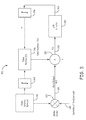
- FIG. 3 is a block diagram of a MEMS sensor north seeker system 300 according to another embodiment, which can implement the closed feedback loop described above.
- the system 300 includes similar components as system 200 discussed previously, except for the feedback loop configuration.
- system 300 includes at least one MEMS sensor that is coupled to a spinning device such as a rotating table.
- the MEMs sensor includes a MEMS motor drive, which is coupled to a MEMS sensor rate output 320 through a gyroscope 322.
- a frequency divider is in communication with a motor signal output.
- a spinning device motor such as a table motor is operatively coupled to the spinning device and is in operative communication with the frequency divider.
- a phase detector or multiplier 330 is in operative communication with the table motor.
- the phase detector 330 is also in operative communication with sensor rate output 320.
- a low pass filter (LPF) 350 is in operative communication with phase detector 330.
- LPF low pass filter
- a physical earth signal 340 (earth rate*sin (latitude)) is received at the input axis of the MEMS sensor.
- An output signal from gyroscope 322 is demodulated to get a sinusoidal sensor rate signal R(t), which is directed to phase detector 330 through sensor rate output 320.
- a signal corresponding to a table rotation rate 342 drives modulation of the earth signal 340 onto the sensor input axis.
- a table motor output directs a table position signal T(t) to phase detector 330.
- the position signal comprises a sinusoidal signal corresponding to a table position 346 that has been integrated with the table rotation rate 342 through a first integrator 348.
- the position signal T(t) is compared to the sensor rate signal R(t) in phase detector 330 to determine a phase difference between the position signal and the sensor rate signal.
- the phase difference is used to generate a phase differential output signal (Y(t)), which is directed from an output 332 of phase detector 330 to LPF 350.
- An LPF output 352 directs a feedback signal in a closed loop to a second integrator 354, which is used to integrate the feedback signal with the table position signal from the table motor.
- the closed feedback loop configuration of system 300 can be used to improve accuracy and eliminate the requirement for a calibrated rate gyroscope.
- the relative direction to true north is determined from the phase differential between the spinning device position signal and the sensor rate signal.
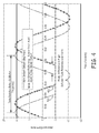
- Figure 4 is a graph showing the performance of a MEMS sensor north seeker system according to the present invention.
- the graph shows the measured earth rate signal with respect to time.
- the rate sensor signal output has a sinusoidal curve 410 corresponding to an earth rate in degrees/hour.
- the table reference signal output has a sinusoidal curve 420 corresponding to Sin (ground reference minus sensor input axis).
- the curve 420 has been scaled to the maximum sensor signal output to match its amplitude with the amplitude of curve 410 for ease of comparison.
- the wavelength of the sinusoidal curves corresponds to the table rotation rate which is equal to K/(motor frequency).
- the phase difference between curves 410 and 420 gives the angle between the table reference and true north. Thus, for example, if the phase difference is 60 degrees, then the direction to true north is at angle of 60 degrees from the current direction.
- Instructions for carrying out the various process tasks, calculations, and generation of signals and other data used in the operation of the system and method of the invention can be implemented in software, firmware, or other computer readable instructions. These instructions are typically stored on any appropriate computer readable media used for storage of computer readable instructions or data structures. Such computer readable media can be any available media that can be accessed by a general purpose or special purpose computer or processor, or any programmable logic device.
- Suitable computer readable media may comprise, for example, non-volatile memory devices including semiconductor memory devices such as ROM, EPROM, EEPROM, or flash memory devices; magnetic disks such as internal hard disks or removable disks; magneto-optical disks; CDs, DVDs, or other optical storage disks; non-volatile RAM, and other like media; or any other media that can be used to carry or store desired program code means in the form of computer executable instructions or data structures. Any of the foregoing may be supplemented by, or incorporated in, specially-designed application-specific integrated circuits (ASICs), or field programmable gate arrays (FPGAs).
- ASICs application-specific integrated circuits
- FPGAs field programmable gate arrays
Landscapes
- Life Sciences & Earth Sciences (AREA)
- Environmental & Geological Engineering (AREA)
- General Life Sciences & Earth Sciences (AREA)
- Geology (AREA)
- Physics & Mathematics (AREA)
- Engineering & Computer Science (AREA)
- General Physics & Mathematics (AREA)
- Radar, Positioning & Navigation (AREA)
- Remote Sensing (AREA)
- Gyroscopes (AREA)
Applications Claiming Priority (1)
| Application Number | Priority Date | Filing Date | Title |
|---|---|---|---|
| US11/833,398 US7412775B1 (en) | 2007-08-03 | 2007-08-03 | Gyroscope north seeker system and method |
Publications (3)
| Publication Number | Publication Date |
|---|---|
| EP2026036A2 true EP2026036A2 (de) | 2009-02-18 |
| EP2026036A3 EP2026036A3 (de) | 2012-11-14 |
| EP2026036B1 EP2026036B1 (de) | 2014-02-12 |
Family
ID=39687157
Family Applications (1)
| Application Number | Title | Priority Date | Filing Date |
|---|---|---|---|
| EP08161509.8A Active EP2026036B1 (de) | 2007-08-03 | 2008-07-30 | Gyroskopisches Nordsuchsystem und -verfahren |
Country Status (2)
| Country | Link |
|---|---|
| US (1) | US7412775B1 (de) |
| EP (1) | EP2026036B1 (de) |
Cited By (2)
| Publication number | Priority date | Publication date | Assignee | Title |
|---|---|---|---|---|
| CN112146643A (zh) * | 2020-09-25 | 2020-12-29 | 重庆天箭惯性科技股份有限公司 | 光纤陀螺寻北仪 |
| US12399005B2 (en) | 2020-10-30 | 2025-08-26 | Murata Manufacturing Co., Ltd. | MEMS gyrocompass |
Families Citing this family (25)
| Publication number | Priority date | Publication date | Assignee | Title |
|---|---|---|---|---|
| RU2526763C2 (ru) * | 2008-02-11 | 2014-08-27 | Квалкомм Мемс Текнолоджис, Инк. | Способ и устройство считывания, измерения или определения параметров дисплейных элементов, объединенных со схемой управления дисплеем, а также система, в которой применены такие способ и устройство |
| KR20100126352A (ko) * | 2008-02-11 | 2010-12-01 | 퀄컴 엠이엠스 테크놀로지스, 인크. | 간섭계 변조기의 측정 및 평가 방법 |
| US8258800B2 (en) * | 2008-02-11 | 2012-09-04 | Qualcomm Mems Technologies, Inc. | Methods for measurement and characterization of interferometric modulators |
| US8466858B2 (en) * | 2008-02-11 | 2013-06-18 | Qualcomm Mems Technologies, Inc. | Sensing to determine pixel state in a passively addressed display array |
| US20090201282A1 (en) * | 2008-02-11 | 2009-08-13 | Qualcomm Mems Technologies, Inc | Methods of tuning interferometric modulator displays |
| US8027800B2 (en) | 2008-06-24 | 2011-09-27 | Qualcomm Mems Technologies, Inc. | Apparatus and method for testing a panel of interferometric modulators |
| US20130211723A1 (en) * | 2009-01-30 | 2013-08-15 | Gyrodata, Incorporated | Reducing error contributions to gyroscopic measurements |
| IL198109A (en) * | 2009-04-07 | 2013-01-31 | Azimuth Technologies Ltd | Facility, system and method for finding the north |
| US8464433B1 (en) * | 2009-07-07 | 2013-06-18 | Milli Sensor Systems & Actuators, Inc. | Human-portable MEMS Azimuth sensing unit and method |
| US8521428B1 (en) * | 2009-10-15 | 2013-08-27 | Moog Inc. | Heading determination using sensors mounted on rotatable assembly |
| FR2961305B1 (fr) | 2010-06-14 | 2012-06-22 | Eurocopter France | Dispositif de mesure inertielle ameliore et aeronef comportant un tel dispositif |
| IL206459A (en) | 2010-06-17 | 2015-11-30 | Rafael Advanced Defense Sys | North origin |
| IL209261A0 (en) * | 2010-11-11 | 2011-01-31 | Israel Aerospace Ind Ltd | A system and method for north finding |
| DE102010061726A1 (de) * | 2010-11-22 | 2012-05-24 | Hilti Aktiengesellschaft | Rotationslasergerät und Verfahren zur Steuerung eines Laserstrahls |
| US9134131B2 (en) | 2011-04-07 | 2015-09-15 | Icefield Tools Corporation | Method and apparatus for determining orientation using a plurality of angular rate sensors and accelerometers |
| ITMC20120024A1 (it) * | 2012-03-23 | 2013-09-24 | Civitanavi Systems Di Andrea Pizzar Ulli | Sistema e metodo per la ricerca del nord geografico e dell'assetto |
| CN103776434B (zh) * | 2012-10-23 | 2017-10-20 | 于中权 | 新型陀螺寻北仪和寻北方法 |
| CN103091662B (zh) * | 2013-01-09 | 2015-08-05 | 上海大唐移动通信设备有限公司 | 定位方法、路测终端与手持终端 |
| DE102013107294A1 (de) * | 2013-07-10 | 2015-01-15 | Gustav Klauke Gmbh | Handarbeitsgerät und Hand-Aufweitgerät |
| DE102015017042A1 (de) | 2015-02-09 | 2016-08-11 | Dieter Schödlbauer | Anordnung und Verfahren zur Suche der geografischen Nordrichtung |
| US11946771B2 (en) | 2020-04-01 | 2024-04-02 | Industrial Technology Research Institute | Aerial vehicle and orientation detection method using same |
| CN113984033A (zh) * | 2021-10-18 | 2022-01-28 | 华中光电技术研究所(中国船舶重工集团公司第七一七研究所) | 一种基于四脉冲原子干涉陀螺仪的寻北方法及系统 |
| CN114910059B (zh) * | 2022-06-13 | 2024-07-02 | 清华大学 | 一种小型化mems陀螺寻北仪 |
| CN115655316B (zh) * | 2022-12-22 | 2023-03-10 | 中国船舶集团有限公司第七〇七研究所 | 基于地球位置变化的光纤陀螺精度测试方法 |
| CN118706099B (zh) * | 2024-08-27 | 2024-12-17 | 南京理工大学 | 一种芯片行波马达式陀螺寻北仪 |
Citations (3)
| Publication number | Priority date | Publication date | Assignee | Title |
|---|---|---|---|---|
| US5272922A (en) | 1991-03-06 | 1993-12-28 | Watson Industries, Inc. | Vibrating element angular rate sensor system and north seeking gyroscope embodiment thereof |
| US5349855A (en) | 1992-04-07 | 1994-09-27 | The Charles Stark Draper Laboratory, Inc. | Comb drive micromechanical tuning fork gyro |
| US7036373B2 (en) | 2004-06-29 | 2006-05-02 | Honeywell International, Inc. | MEMS gyroscope with horizontally oriented drive electrodes |
Family Cites Families (6)
| Publication number | Priority date | Publication date | Assignee | Title |
|---|---|---|---|---|
| US3961535A (en) * | 1975-02-10 | 1976-06-08 | Sanders Associates, Inc. | Spin rate compensator |
| US4351194A (en) * | 1980-05-01 | 1982-09-28 | The Singer Company | Gyro autophase system |
| FR2511502A1 (fr) * | 1981-08-17 | 1983-02-18 | Sfim | Procede et dispositif de recherche gyroscopique du nord |
| US4559713A (en) * | 1982-02-24 | 1985-12-24 | Applied Technologies Associates | Azimuth determination for vector sensor tools |
| US7096591B2 (en) * | 2004-04-08 | 2006-08-29 | Trimble Navigation Limited | Dual axis single motor platform adjustments system |
| US20070106457A1 (en) * | 2005-11-09 | 2007-05-10 | Outland Research | Portable computing with geospatial haptic compass |
-
2007
- 2007-08-03 US US11/833,398 patent/US7412775B1/en active Active
-
2008
- 2008-07-30 EP EP08161509.8A patent/EP2026036B1/de active Active
Patent Citations (3)
| Publication number | Priority date | Publication date | Assignee | Title |
|---|---|---|---|---|
| US5272922A (en) | 1991-03-06 | 1993-12-28 | Watson Industries, Inc. | Vibrating element angular rate sensor system and north seeking gyroscope embodiment thereof |
| US5349855A (en) | 1992-04-07 | 1994-09-27 | The Charles Stark Draper Laboratory, Inc. | Comb drive micromechanical tuning fork gyro |
| US7036373B2 (en) | 2004-06-29 | 2006-05-02 | Honeywell International, Inc. | MEMS gyroscope with horizontally oriented drive electrodes |
Cited By (2)
| Publication number | Priority date | Publication date | Assignee | Title |
|---|---|---|---|---|
| CN112146643A (zh) * | 2020-09-25 | 2020-12-29 | 重庆天箭惯性科技股份有限公司 | 光纤陀螺寻北仪 |
| US12399005B2 (en) | 2020-10-30 | 2025-08-26 | Murata Manufacturing Co., Ltd. | MEMS gyrocompass |
Also Published As
| Publication number | Publication date |
|---|---|
| EP2026036B1 (de) | 2014-02-12 |
| US7412775B1 (en) | 2008-08-19 |
| EP2026036A3 (de) | 2012-11-14 |
Similar Documents
| Publication | Publication Date | Title |
|---|---|---|
| EP2026036B1 (de) | Gyroskopisches Nordsuchsystem und -verfahren | |
| Curey et al. | Proposed IEEE inertial systems terminology standard and other inertial sensor standards | |
| EP2239540B1 (de) | Auf einem Goniometer montierbarer Kreiselkompass | |
| US7481109B2 (en) | Inertial measurement system and method with bias cancellation | |
| EP1250564B1 (de) | Vibrationsgyroskop | |
| EP2583059B1 (de) | Verbesserter kompass | |
| US10309786B2 (en) | Navigational and location determination system | |
| US4800501A (en) | Vehicle land navigating device | |
| US9714548B2 (en) | Apparatus for single degree of freedom inertial measurement unit platform rate isolation | |
| US8521428B1 (en) | Heading determination using sensors mounted on rotatable assembly | |
| Eminoglu et al. | Background calibrated MEMS gyroscope | |
| Miao et al. | Virtual rotating MEMS gyrocompassing with honeycomb disk resonator gyroscope | |
| EP2005199B1 (de) | Trägheitsmesssystem und verfahren mit abweichungskorrektur | |
| US6842153B2 (en) | Instrument alignment devices and methods | |
| EP3748294B1 (de) | Richtungsfinder | |
| CN102648391A (zh) | 通过转动惯性装置来确定航向的方法 | |
| EP0026205B1 (de) | Kreiselkompass | |
| CN101398304B (zh) | 一种摆式陀螺寻北仪寻北测量方法 | |
| Tang et al. | Investigation on influences of phase delay on performance of resonator gyroscopes | |
| Xing et al. | Analysis of dynamic north finding based on multiple low-precision MIMUs | |
| CN114894216B (zh) | 微机电陀螺寻北仪精度提升方法及微机电陀螺寻北仪 | |
| US9879996B2 (en) | System and method of electrostatic carouseling for gyrocompassing | |
| US3293923A (en) | Arrangement for inertia navigation by means of gyroscopes | |
| Liang et al. | High-Precision MEMS North-Finding System in the Whole Temperature Range with Honeycomb Disk Resonator Gyroscope | |
| Parvin | Inertial navigation systems: Prelaunch alignment |
Legal Events
| Date | Code | Title | Description |
|---|---|---|---|
| PUAI | Public reference made under article 153(3) epc to a published international application that has entered the european phase |
Free format text: ORIGINAL CODE: 0009012 |
|
| 17P | Request for examination filed |
Effective date: 20080730 |
|
| AK | Designated contracting states |
Kind code of ref document: A2 Designated state(s): AT BE BG CH CY CZ DE DK EE ES FI FR GB GR HR HU IE IS IT LI LT LU LV MC MT NL NO PL PT RO SE SI SK TR |
|
| AX | Request for extension of the european patent |
Extension state: AL BA MK RS |
|
| PUAL | Search report despatched |
Free format text: ORIGINAL CODE: 0009013 |
|
| AK | Designated contracting states |
Kind code of ref document: A3 Designated state(s): AT BE BG CH CY CZ DE DK EE ES FI FR GB GR HR HU IE IS IT LI LT LU LV MC MT NL NO PL PT RO SE SI SK TR |
|
| AX | Request for extension of the european patent |
Extension state: AL BA MK RS |
|
| RIC1 | Information provided on ipc code assigned before grant |
Ipc: G01C 19/38 20060101ALI20121010BHEP Ipc: G01C 17/00 20060101AFI20121010BHEP |
|
| 17Q | First examination report despatched |
Effective date: 20121031 |
|
| AKX | Designation fees paid |
Designated state(s): DE FR GB |
|
| GRAP | Despatch of communication of intention to grant a patent |
Free format text: ORIGINAL CODE: EPIDOSNIGR1 |
|
| INTG | Intention to grant announced |
Effective date: 20130920 |
|
| GRAS | Grant fee paid |
Free format text: ORIGINAL CODE: EPIDOSNIGR3 |
|
| GRAA | (expected) grant |
Free format text: ORIGINAL CODE: 0009210 |
|
| AK | Designated contracting states |
Kind code of ref document: B1 Designated state(s): DE FR GB |
|
| REG | Reference to a national code |
Ref country code: GB Ref legal event code: FG4D |
|
| REG | Reference to a national code |
Ref country code: DE Ref legal event code: R096 Ref document number: 602008030232 Country of ref document: DE Effective date: 20140327 |
|
| REG | Reference to a national code |
Ref country code: DE Ref legal event code: R097 Ref document number: 602008030232 Country of ref document: DE |
|
| PLBE | No opposition filed within time limit |
Free format text: ORIGINAL CODE: 0009261 |
|
| STAA | Information on the status of an ep patent application or granted ep patent |
Free format text: STATUS: NO OPPOSITION FILED WITHIN TIME LIMIT |
|
| 26N | No opposition filed |
Effective date: 20141113 |
|
| REG | Reference to a national code |
Ref country code: DE Ref legal event code: R097 Ref document number: 602008030232 Country of ref document: DE Effective date: 20141113 |
|
| REG | Reference to a national code |
Ref country code: FR Ref legal event code: PLFP Year of fee payment: 9 |
|
| REG | Reference to a national code |
Ref country code: FR Ref legal event code: PLFP Year of fee payment: 10 |
|
| PGFP | Annual fee paid to national office [announced via postgrant information from national office to epo] |
Ref country code: IT Payment date: 20170824 Year of fee payment: 10 |
|
| PGFP | Annual fee paid to national office [announced via postgrant information from national office to epo] |
Ref country code: DE Payment date: 20170929 Year of fee payment: 10 |
|
| REG | Reference to a national code |
Ref country code: FR Ref legal event code: PLFP Year of fee payment: 11 |
|
| REG | Reference to a national code |
Ref country code: DE Ref legal event code: R119 Ref document number: 602008030232 Country of ref document: DE |
|
| GBPC | Gb: european patent ceased through non-payment of renewal fee |
Effective date: 20180730 |
|
| PG25 | Lapsed in a contracting state [announced via postgrant information from national office to epo] |
Ref country code: GB Free format text: LAPSE BECAUSE OF NON-PAYMENT OF DUE FEES Effective date: 20180730 Ref country code: DE Free format text: LAPSE BECAUSE OF NON-PAYMENT OF DUE FEES Effective date: 20190201 |
|
| P01 | Opt-out of the competence of the unified patent court (upc) registered |
Effective date: 20230525 |
|
| PGFP | Annual fee paid to national office [announced via postgrant information from national office to epo] |
Ref country code: FR Payment date: 20250725 Year of fee payment: 18 |