EP2026048A1 - Procédé et dispositif destinés à la détermination de la charge d'un véhicule en marche - Google Patents
Procédé et dispositif destinés à la détermination de la charge d'un véhicule en marche Download PDFInfo
- Publication number
- EP2026048A1 EP2026048A1 EP08104928A EP08104928A EP2026048A1 EP 2026048 A1 EP2026048 A1 EP 2026048A1 EP 08104928 A EP08104928 A EP 08104928A EP 08104928 A EP08104928 A EP 08104928A EP 2026048 A1 EP2026048 A1 EP 2026048A1
- Authority
- EP
- European Patent Office
- Prior art keywords
- vehicle
- force
- dyn
- vibration
- determined
- Prior art date
- Legal status (The legal status is an assumption and is not a legal conclusion. Google has not performed a legal analysis and makes no representation as to the accuracy of the status listed.)
- Withdrawn
Links
- 238000000034 method Methods 0.000 title claims abstract description 30
- 230000003068 static effect Effects 0.000 claims abstract description 24
- 238000005259 measurement Methods 0.000 claims abstract description 21
- 238000005303 weighing Methods 0.000 claims description 22
- 238000013528 artificial neural network Methods 0.000 claims description 6
- 238000001514 detection method Methods 0.000 claims description 6
- 238000011156 evaluation Methods 0.000 claims description 6
- 238000004364 calculation method Methods 0.000 claims description 2
- 238000001454 recorded image Methods 0.000 claims description 2
- 230000000694 effects Effects 0.000 description 4
- 230000003534 oscillatory effect Effects 0.000 description 3
- 239000000725 suspension Substances 0.000 description 3
- 230000002123 temporal effect Effects 0.000 description 3
- 230000006399 behavior Effects 0.000 description 2
- 238000005452 bending Methods 0.000 description 2
- 238000013016 damping Methods 0.000 description 2
- 238000006073 displacement reaction Methods 0.000 description 2
- 238000009434 installation Methods 0.000 description 2
- 238000012544 monitoring process Methods 0.000 description 2
- 230000001133 acceleration Effects 0.000 description 1
- 238000013459 approach Methods 0.000 description 1
- 239000003990 capacitor Substances 0.000 description 1
- 238000010276 construction Methods 0.000 description 1
- 238000013480 data collection Methods 0.000 description 1
- 238000013461 design Methods 0.000 description 1
- 238000011496 digital image analysis Methods 0.000 description 1
- 238000012423 maintenance Methods 0.000 description 1
- 238000004519 manufacturing process Methods 0.000 description 1
- 230000010355 oscillation Effects 0.000 description 1
- 238000005096 rolling process Methods 0.000 description 1
- 238000012360 testing method Methods 0.000 description 1
- 238000013519 translation Methods 0.000 description 1
Images
Classifications
-
- G—PHYSICS
- G01—MEASURING; TESTING
- G01G—WEIGHING
- G01G19/00—Weighing apparatus or methods adapted for special purposes not provided for in the preceding groups
- G01G19/02—Weighing apparatus or methods adapted for special purposes not provided for in the preceding groups for weighing wheeled or rolling bodies, e.g. vehicles
- G01G19/022—Weighing apparatus or methods adapted for special purposes not provided for in the preceding groups for weighing wheeled or rolling bodies, e.g. vehicles for weighing wheeled or rolling bodies in motion
- G01G19/024—Weighing apparatus or methods adapted for special purposes not provided for in the preceding groups for weighing wheeled or rolling bodies, e.g. vehicles for weighing wheeled or rolling bodies in motion using electrical weight-sensitive devices
Definitions
- the invention relates to a method for determining the load of a vehicle in motion according to the preamble of claim 1 and to an apparatus for carrying out the method according to claim 10.
- weighing stations For determining the weight of vehicles weighing stations are known, which are to be specially driven by a vehicle to be weighed, the vehicle must stop for weighing. Such weighing stations are arranged, for example, at entrances and exits of factory premises in order to determine the loading weight of trucks at entry and exit. Furthermore, weighing stations are used in traffic controls, for example when checking trucks for their proper state of charge.
- weighing stations have the disadvantage that they are early recognizable due to their design of truck drivers and thus can be avoided. They are also expensive to manufacture and operate. In addition, they hinder the flow of traffic. Finally, all trucks must approach the weighing station, as a vehicle can not be easily seen in advance whether it is properly loaded or overloaded.
- WIM Weigh-In-Motion
- a plurality of such measuring devices is already known whose weighing sensor is embedded in the road surface and which are based on different measuring principles.
- the load impressed on a plate or strip-shaped measuring surface when passing from a wheel or an axle of the vehicle may cause bending of a plate with known bending stress characteristic, pressurization of a piezocrystal, displacement of the plate gap of a plate capacitor, or displacement of a movable bobbin in a coil , from which said effects on the size of the load is deduced.
- These measuring devices are used as weighing platforms or load cells or as a combination of both.
- the measuring device comprises a rubber mat in which a light guide is embedded, along which a plurality of microbiegenden fasteners is arranged.
- the force of a rubber wheel rolling over the vehicle wheel squeezes a fixture, whereby at this point of the light guide loss of light due to deflection occurs.
- the light loss caused by the load is calculated from the measurements of the light fed in at one end of the light guide and exiting at the other end.
- the translation DE 690 03 784 T2 A European patent discloses a balance for weighing moving vehicles. It comprises a base to be anchored to the roadbed below the ground level in the path of the moving vehicles and a platform for receiving the wheels of the vehicles moving vehicles. Load cell means are provided between the base and the platform for delivering signals indicative of the loads applied by the wheels to the platform. Coupled between the platform and the base is a device, preferably formed by at least one flexure or flexure, which applies an initial load or bias therebetween and permits relative movement in the vertical direction but resists relative horizontal movement.
- the known weighing devices suffer from the disadvantage that they are relatively inaccurate compared to stationary vehicle scales. In particular, there are problems associated with calibrating the devices to extract static loads from dynamic load information.
- the invention is therefore based on the object to provide a method and an apparatus of the type mentioned, so that load determinations of vehicles in motion can be performed with a higher accuracy.
- the task-related to the device part of the invention is achieved by a generic method for determining a vehicle load of a vehicle in motion, in which the specified in the characterizing part of claim 1 steps are performed.
- the invention is based on the fact that during the measurement of wheel and axle weights of vehicles when driving, the weighing sensor is subjected to various dynamic effects of the vehicle spring-mass damping system and its eigenvalues.
- the permanent exchange of energy between the vehicle masses, suspension elements and dampers with the road, especially on rough roads and imbalances in vehicle elements causes a dynamic force component, which is superimposed on a static vehicle load. It is therefore according to the invention a vibration state of the vehicle in motion at the time of at least one force measurement determined.
- a vibration-related force component of the dynamic measured force is then calculated, from which it is possible to infer the static force component of the dynamically measured force. From this, finally, the vehicle load to be determined, ie wheel, axle or total load of the vehicle, determined. As a result, an improvement of the measurement accuracy of 10 to 20% can be achieved.
- the vibration state is determined by taking a digital image series of the vehicle in motion.
- the image series allows a temporal observation of the vehicle oscillated by its travel in order to determine the amplitudes and vibration durations of the possibly superimposed vehicle vibrations.
- computer-aided evaluation methods can be used.
- the recorded images are evaluated for a vibration movement of a distinctive vehicle element. From the trajectory of a vibrating element of the vehicle relative to the roadway on which the vehicle is moving, it is possible to deduce the oscillation phase in which the vehicle is at the time of the force measurement. To observe a trajectory, a striking vehicle element, which can preferably be found automatically on the digital images, is tracked.
- a distinctive point of the vehicle body is used as the vehicle element. Corners or edges of the cab or trailer of the vehicle, but also arranged thereon characters can be well detected by digital image analysis and their position can be determined.
- a center point of a vehicle wheel is used as the vehicle element.
- a wheel center Compared to the vehicle body performs a less pronounced vibration movement while driving and can therefore serve as a reference point for other prominent elements.
- the static force component is determined from the determined vibration state and the dynamically measured force on the basis of a vibration model of the vehicle.
- Vibration models are known, for example, from the respective manufacturers of trucks. From the observed vibration behavior can be concluded on the basis of a given vehicle type associated vibration model on the vibration state at a given time.
- the static force component is determined from the determined vibration state and the dynamically measured force on the basis of a neural network.
- the neural network can be trained on the basis of assignments of previous image recordings to subsequently performed stationary, static load measurements.
- the dynamic force measurement is repeated at predetermined intervals.
- the underlying vibration model or neural network can be verified, since in general every time a different vibration state is determined. This improves the accuracy of the load determination method.
- the speed of the vehicle is measured at the time of the force measurement and taken into account for the calculation of the static force component.
- the dynamic state of motion of the vehicle in particular the magnitude of the vibration amplitudes, depends essentially on the speed of the vehicle.
- the speed is determined from the recorded digital image series. From the temporal change in size of a distinctive length or surface of the vehicle can be closed at a known viewing direction of an image pickup device relative to the vehicle at its speed. This eliminates the cost of a separate speed sensors.
- the vehicle speed can also be measured by means of a weighing sensor and / or a radar detector and / or a laser detector.
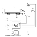
- a device 10 for determining a vehicle load of a vehicle F in motion has a weighing sensor 20 for dynamic force measurement, a detection device for determining a vibration state and an evaluation device 40 for determining a static vehicle load from the determined vibration state and the dynamically measured force f dyn ,
- the weighing sensor 20 is embodied as a weighing plate or piezosensor embedded in the surface of the road S, as it passes through the vehicle F exerts a force f exerted by a single wheel R or a group of wheels of an axle of the vehicle F on a measuring surface of the weighing sensor 20 f dyn is measured.
- the dynamically measured force f dyn has a static force component f sta , which is based on the dead weight and the load of the vehicle F, and a vibration-related force component f ⁇ , which is due to the vehicle vibrations of the vehicle in motion F.
- the vibration induced force component f ⁇ and from this the static force component f sta will now be calculated according to the invention, to determine the vehicle load, respectively searched.
- the oscillatory movements of the vehicle F for example a truck with tractor and semi-trailer, result from a superimposition of a multiplicity of different effects.
- This is influenced by the quality of the surface and the stability of the substructure of the road S, the nature of the measuring point - ie the flatness of the arrival and departure area and the horizontal and vertical slope of the road S - the driving behavior of the driver - ie braking, acceleration, Steering movements - and the condition of the vehicle, such as suspension and damping system, wheel and tire imbalances and type of cargo.
- the detection device additionally has a radar detector 31, by means of which the speed v of the vehicle F at the force measuring point is measured. Furthermore, an unillustrated laser detector and a likewise not shown ultrasonic detector at the measuring point be arranged, which serve for the temporal distance measurement to or on the vehicle F.
- the detection devices 30, 31 transmit their data to the evaluation device 40, which comprises a computing unit 41, a memory unit 42 and an output unit 43.
- the image data b i transmitted by the video camera 30 are evaluated on the basis of a known vibration model m and / or a neural network n which are stored in the memory unit 42.
- a striking vehicle element for example a prominent point P of the vehicle body A and / or a center M of a vehicle wheel R, is tracked and the vibration state of the vehicle F at the time of the force measurement is determined from the oscillatory motion.
- the measured vehicle speed v and further distance measurement values are also taken into account.
- the vibration-related force component f ⁇ can now be determined by the computing unit 41.
- the vibration-related force component f ⁇ however, the static force component f sta of the dynamically measured force f dyn and thus the wheel or axle load to be determined are also fixed. From this, however, the total load of the vehicle F can also be determined and displayed on the output unit 43 of the evaluation device 40 designed as a screen for a monitoring personnel.
- the method according to the invention or the device for carrying out the method allows a more accurate determination of vehicle weights or axle loads, as it can afford the previous single measurement of the force exerted on the road S force.
- This opens up new applications that require an increased level of measurement accuracy, such as the fully automatic overhaul of overcharges or the automatic, assured capture of actual vehicle weights for a weight-based toll collection process.
- additional Sensors may be dispensed with the complex and costly installation of many weighing sensors in the road surface, which in addition to the increased measurement accuracy and a cost advantage in installation and maintenance of a system according to the invention can be achieved.
Landscapes
- Physics & Mathematics (AREA)
- General Physics & Mathematics (AREA)
- Traffic Control Systems (AREA)
Applications Claiming Priority (1)
| Application Number | Priority Date | Filing Date | Title |
|---|---|---|---|
| DE200710036991 DE102007036991A1 (de) | 2007-08-06 | 2007-08-06 | Verfahren und Vorrichtung zur Lastbestimmung eines in Fahrt befindlichen Fahrzeuges |
Publications (1)
| Publication Number | Publication Date |
|---|---|
| EP2026048A1 true EP2026048A1 (fr) | 2009-02-18 |
Family
ID=39879269
Family Applications (1)
| Application Number | Title | Priority Date | Filing Date |
|---|---|---|---|
| EP08104928A Withdrawn EP2026048A1 (fr) | 2007-08-06 | 2008-07-31 | Procédé et dispositif destinés à la détermination de la charge d'un véhicule en marche |
Country Status (3)
| Country | Link |
|---|---|
| EP (1) | EP2026048A1 (fr) |
| CN (1) | CN101363751A (fr) |
| DE (1) | DE102007036991A1 (fr) |
Cited By (5)
| Publication number | Priority date | Publication date | Assignee | Title |
|---|---|---|---|---|
| CN102799897A (zh) * | 2012-07-02 | 2012-11-28 | 杨飞 | 基于gps定位的交通方式组合出行的计算机识别方法 |
| WO2020120253A1 (fr) * | 2018-12-14 | 2020-06-18 | Kistler Holding Ag | Étalonnage d'un capteur wim |
| CN111735523A (zh) * | 2020-08-27 | 2020-10-02 | 湖南大学 | 基于视频识别的车重检测方法、装置及存储介质 |
| CN112781702A (zh) * | 2020-12-30 | 2021-05-11 | 北京万集科技股份有限公司 | 一种对车辆称重的方法及系统 |
| CN112798089A (zh) * | 2020-12-30 | 2021-05-14 | 北京万集科技股份有限公司 | 一种车辆的动态称重方法及动态称重装置 |
Families Citing this family (8)
| Publication number | Priority date | Publication date | Assignee | Title |
|---|---|---|---|---|
| CN104089690B (zh) * | 2014-07-02 | 2016-06-29 | 江苏大学 | 收费站车辆动态称重估算方法与装置 |
| CN105181201A (zh) * | 2015-07-18 | 2015-12-23 | 广西大学 | 行驶中的汽车与地面之间的压力的测试方法 |
| CN105865597B (zh) * | 2016-06-22 | 2018-06-01 | 锐马(福建)电气制造有限公司 | 一种车载称重方法 |
| CN109781228B (zh) * | 2019-01-30 | 2021-08-24 | 内蒙古大学 | 车辆载荷确定系统和方法 |
| CN112309108B (zh) * | 2019-08-01 | 2022-01-28 | 保定市天河电子技术有限公司 | 一种货车车载超限检测系统及方法 |
| CN110440889B (zh) * | 2019-09-04 | 2023-08-29 | 广东泓胜科技股份有限公司 | 一种石英晶体传感器组合的不停车称重检测装置及方法 |
| CN110702195B (zh) * | 2019-09-24 | 2021-06-25 | 北京化工大学 | 载重车辆运行状态监测方法及装置 |
| CN111922535B (zh) * | 2020-08-12 | 2022-02-18 | 淮北特兰奇地毯有限公司 | 一种智能化地毯用激光打孔器及其工作方法 |
Citations (8)
| Publication number | Priority date | Publication date | Assignee | Title |
|---|---|---|---|---|
| US3276525A (en) * | 1964-06-15 | 1966-10-04 | Canadian Nat Railway Co | Method and apparatus for dynamically weighing objects in motion |
| US3446299A (en) * | 1965-03-03 | 1969-05-27 | Avery Ltd W & T | Dynamic weighing |
| US4560016A (en) | 1983-12-14 | 1985-12-24 | Anco Engineers, Incorporated | Method and apparatus for measuring the weight of a vehicle while the vehicle is in motion |
| DE3912144A1 (de) * | 1989-04-13 | 1990-10-18 | Bosch Gmbh Robert | Verfahren und vorrichtung zur achslastbestimmung eines fahrzeugs |
| DE69003784T2 (de) | 1989-08-22 | 1994-04-28 | Mettler Toledo Inc | Waage zum Wiegen sich bewegender Fahrzeuge. |
| US5773766A (en) * | 1996-03-06 | 1998-06-30 | Matsushita Electric Industrial Co., Ltd. | Axle load scale |
| WO1999045346A1 (fr) * | 1998-03-04 | 1999-09-10 | Controload Ltd. | Procede de determination du poids et du centre de masse d'un vehicule en mouvement grace a un systeme incorpore |
| DE10114481A1 (de) * | 2001-03-24 | 2002-09-26 | Schenck Process Gmbh | Verfahren und Vorrichtung zur dynamischen Messung der Achslast oder des Gewichts von Fahrzeugen |
Family Cites Families (1)
| Publication number | Priority date | Publication date | Assignee | Title |
|---|---|---|---|---|
| JP3467906B2 (ja) * | 1995-05-22 | 2003-11-17 | 松下電器産業株式会社 | 軸重計測装置 |
-
2007
- 2007-08-06 DE DE200710036991 patent/DE102007036991A1/de not_active Ceased
-
2008
- 2008-07-31 EP EP08104928A patent/EP2026048A1/fr not_active Withdrawn
- 2008-08-06 CN CNA200810146005XA patent/CN101363751A/zh active Pending
Patent Citations (8)
| Publication number | Priority date | Publication date | Assignee | Title |
|---|---|---|---|---|
| US3276525A (en) * | 1964-06-15 | 1966-10-04 | Canadian Nat Railway Co | Method and apparatus for dynamically weighing objects in motion |
| US3446299A (en) * | 1965-03-03 | 1969-05-27 | Avery Ltd W & T | Dynamic weighing |
| US4560016A (en) | 1983-12-14 | 1985-12-24 | Anco Engineers, Incorporated | Method and apparatus for measuring the weight of a vehicle while the vehicle is in motion |
| DE3912144A1 (de) * | 1989-04-13 | 1990-10-18 | Bosch Gmbh Robert | Verfahren und vorrichtung zur achslastbestimmung eines fahrzeugs |
| DE69003784T2 (de) | 1989-08-22 | 1994-04-28 | Mettler Toledo Inc | Waage zum Wiegen sich bewegender Fahrzeuge. |
| US5773766A (en) * | 1996-03-06 | 1998-06-30 | Matsushita Electric Industrial Co., Ltd. | Axle load scale |
| WO1999045346A1 (fr) * | 1998-03-04 | 1999-09-10 | Controload Ltd. | Procede de determination du poids et du centre de masse d'un vehicule en mouvement grace a un systeme incorpore |
| DE10114481A1 (de) * | 2001-03-24 | 2002-09-26 | Schenck Process Gmbh | Verfahren und Vorrichtung zur dynamischen Messung der Achslast oder des Gewichts von Fahrzeugen |
Cited By (9)
| Publication number | Priority date | Publication date | Assignee | Title |
|---|---|---|---|---|
| CN102799897A (zh) * | 2012-07-02 | 2012-11-28 | 杨飞 | 基于gps定位的交通方式组合出行的计算机识别方法 |
| CN102799897B (zh) * | 2012-07-02 | 2014-09-17 | 杨飞 | 基于gps定位的交通方式组合出行的计算机识别方法 |
| WO2020120253A1 (fr) * | 2018-12-14 | 2020-06-18 | Kistler Holding Ag | Étalonnage d'un capteur wim |
| US12031855B2 (en) | 2018-12-14 | 2024-07-09 | Kistler Holding Ag | Calibration of a WIM sensor |
| CN111735523A (zh) * | 2020-08-27 | 2020-10-02 | 湖南大学 | 基于视频识别的车重检测方法、装置及存储介质 |
| CN112781702A (zh) * | 2020-12-30 | 2021-05-11 | 北京万集科技股份有限公司 | 一种对车辆称重的方法及系统 |
| CN112798089A (zh) * | 2020-12-30 | 2021-05-14 | 北京万集科技股份有限公司 | 一种车辆的动态称重方法及动态称重装置 |
| CN112798089B (zh) * | 2020-12-30 | 2023-09-15 | 北京万集科技股份有限公司 | 一种车辆的动态称重方法及动态称重装置 |
| CN112781702B (zh) * | 2020-12-30 | 2023-12-22 | 北京万集科技股份有限公司 | 一种对车辆称重的方法及系统 |
Also Published As
| Publication number | Publication date |
|---|---|
| DE102007036991A1 (de) | 2009-02-12 |
| CN101363751A (zh) | 2009-02-11 |
Similar Documents
| Publication | Publication Date | Title |
|---|---|---|
| EP2026048A1 (fr) | Procédé et dispositif destinés à la détermination de la charge d'un véhicule en marche | |
| EP2553405B1 (fr) | Procédé pour étalonner des détecteurs wim | |
| EP2450865B1 (fr) | Dispositifs et procédés de contrôle mobile pour véhicules | |
| DE69931535T2 (de) | Nutzlastüberwachungsvorrichtung für ein Zugfahrzeug mit Anhänger | |
| EP2850401B1 (fr) | Module capteur d'un système wim et procédé de mesure | |
| EP0756701B1 (fr) | Procede pour la determination des caracteristiques des amortisseurs montes sur un vehicule | |
| EP2687818B1 (fr) | Procédé et dispositif pour cartographier des états routiers | |
| DE102007018192A1 (de) | Rad, Prüfstand und Verfahren zur Ermittlung von aerodynamischen Kennwerten eines Testfahrzeugs | |
| EP1856680B1 (fr) | Procede et installation pour determiner et controler l'etat de charge d'automobiles dans un trafic en circulation et pour peser posterieurement au cas par cas, de maniere adaptee a un etalonnage, des automobiles en surcharge | |
| EP2159561A2 (fr) | Procédé et dispositif d'essai d'un amortisseur d'oscillations d'un véhicule automobile en état intégré | |
| WO2017029084A1 (fr) | Dispositif de contrôle et procédé de contrôle d'un profil défini d'un convoi composé de véhicules, notamment de véhicules ferroviaires | |
| EP2378263B1 (fr) | Système et procédé de détermination du centre de gravité de la masse dans des véhicules sur rails | |
| WO2009109158A1 (fr) | Système et procédé de calibrage des capteurs d’un système de mesure et d’acquisition dynamiques de la charge de roue ou d’essieu de véhicules routiers | |
| AT524256B1 (de) | Verfahren zur Ermittlung eines Reibbeiwertes | |
| EP1224449B1 (fr) | Procede et dispositif pour la verification de composantes de suspension de roue d'un vehicule | |
| AT506047B1 (de) | Vorrichtung zur bestimmung von rad- und/oder achslasten und/oder gesamtgewichten von fahrenden strassenfahrzeugen | |
| DE102011120022A1 (de) | Verfahren zur Klassifizierung des Oberflächenprofils einer Fahrban mittels eines Fahrzeugs | |
| EP3376484B1 (fr) | Procédé et système destinés à compléter une carte numérique stockée sur un ordinateur central d'un réseau routier | |
| EP3037801B1 (fr) | Procede et dispositif de determination de la force d'appui dynamique d'une roue | |
| DE102021120557B4 (de) | Kalibriersystem | |
| DE102015113357B4 (de) | Verfahren zur Analyse und/oder Überwachung von Brücken sowie ein entsprechendes System | |
| EP2738538B1 (fr) | Procédé et véhicule automobile pour détecter des sollicitations qui s'exercent sur un véhicule automobile | |
| DE102010046586A1 (de) | Verkehrsstauerfassung | |
| DE102016101701A1 (de) | Verfahren zum Überprüfen einer Fahrtroute für ein Transportfahrzeug, insbesondere zum Durchführen eines Großraum- und/oder Schwertransports | |
| DE3643470A1 (de) | Verfahren und vorrichtung zum ermitteln des geometrischen profiles von fahrbahnoberflaechen |
Legal Events
| Date | Code | Title | Description |
|---|---|---|---|
| PUAI | Public reference made under article 153(3) epc to a published international application that has entered the european phase |
Free format text: ORIGINAL CODE: 0009012 |
|
| AK | Designated contracting states |
Kind code of ref document: A1 Designated state(s): AT BE BG CH CY CZ DE DK EE ES FI FR GB GR HR HU IE IS IT LI LT LU LV MC MT NL NO PL PT RO SE SI SK TR |
|
| AX | Request for extension of the european patent |
Extension state: AL BA MK RS |
|
| AKX | Designation fees paid | ||
| STAA | Information on the status of an ep patent application or granted ep patent |
Free format text: STATUS: THE APPLICATION IS DEEMED TO BE WITHDRAWN |
|
| 18D | Application deemed to be withdrawn |
Effective date: 20090819 |
|
| REG | Reference to a national code |
Ref country code: DE Ref legal event code: 8566 |