EP2026083A2 - Appareil doté d'un électro-aimant supraconducteur à bouclier actif pour IRM avec protection améliorée lors d'une transition de l'état supraconducteur à l'état normal - Google Patents
Appareil doté d'un électro-aimant supraconducteur à bouclier actif pour IRM avec protection améliorée lors d'une transition de l'état supraconducteur à l'état normal Download PDFInfo
- Publication number
- EP2026083A2 EP2026083A2 EP08252646A EP08252646A EP2026083A2 EP 2026083 A2 EP2026083 A2 EP 2026083A2 EP 08252646 A EP08252646 A EP 08252646A EP 08252646 A EP08252646 A EP 08252646A EP 2026083 A2 EP2026083 A2 EP 2026083A2
- Authority
- EP
- European Patent Office
- Prior art keywords
- coil
- shield
- main coil
- main
- current
- Prior art date
- Legal status (The legal status is an assumption and is not a legal conclusion. Google has not performed a legal analysis and makes no representation as to the accuracy of the status listed.)
- Granted
Links
Images



Classifications
-
- G—PHYSICS
- G01—MEASURING; TESTING
- G01R—MEASURING ELECTRIC VARIABLES; MEASURING MAGNETIC VARIABLES
- G01R33/00—Arrangements or instruments for measuring magnetic variables
- G01R33/20—Arrangements or instruments for measuring magnetic variables involving magnetic resonance
- G01R33/28—Details of apparatus provided for in groups G01R33/44 - G01R33/64
- G01R33/38—Systems for generation, homogenisation or stabilisation of the main or gradient magnetic field
- G01R33/381—Systems for generation, homogenisation or stabilisation of the main or gradient magnetic field using electromagnets
- G01R33/3815—Systems for generation, homogenisation or stabilisation of the main or gradient magnetic field using electromagnets with superconducting coils, e.g. power supply therefor
-
- G—PHYSICS
- G01—MEASURING; TESTING
- G01R—MEASURING ELECTRIC VARIABLES; MEASURING MAGNETIC VARIABLES
- G01R33/00—Arrangements or instruments for measuring magnetic variables
- G01R33/20—Arrangements or instruments for measuring magnetic variables involving magnetic resonance
- G01R33/28—Details of apparatus provided for in groups G01R33/44 - G01R33/64
- G01R33/38—Systems for generation, homogenisation or stabilisation of the main or gradient magnetic field
- G01R33/3806—Open magnet assemblies for improved access to the sample, e.g. C-type or U-type magnets
-
- G—PHYSICS
- G01—MEASURING; TESTING
- G01R—MEASURING ELECTRIC VARIABLES; MEASURING MAGNETIC VARIABLES
- G01R33/00—Arrangements or instruments for measuring magnetic variables
- G01R33/20—Arrangements or instruments for measuring magnetic variables involving magnetic resonance
- G01R33/28—Details of apparatus provided for in groups G01R33/44 - G01R33/64
- G01R33/42—Screening
- G01R33/421—Screening of main or gradient magnetic field
-
- H—ELECTRICITY
- H01—ELECTRIC ELEMENTS
- H01F—MAGNETS; INDUCTANCES; TRANSFORMERS; SELECTION OF MATERIALS FOR THEIR MAGNETIC PROPERTIES
- H01F6/00—Superconducting magnets; Superconducting coils
- H01F6/02—Quenching; Protection arrangements during quenching
-
- G—PHYSICS
- G01—MEASURING; TESTING
- G01R—MEASURING ELECTRIC VARIABLES; MEASURING MAGNETIC VARIABLES
- G01R33/00—Arrangements or instruments for measuring magnetic variables
- G01R33/20—Arrangements or instruments for measuring magnetic variables involving magnetic resonance
- G01R33/28—Details of apparatus provided for in groups G01R33/44 - G01R33/64
- G01R33/288—Provisions within MR facilities for enhancing safety during MR, e.g. reduction of the specific absorption rate [SAR], detection of ferromagnetic objects in the scanner room
Definitions
- the present invention relates to an active shield superconducting electromagnet apparatus and a magnetic resonance imaging (hereinafter, referred to as MRI) system using the same.
- MRI magnetic resonance imaging
- the MRI system can image a living body tissue by utilizing the fact that the nuclear magnetic resonance (hereinafter, referred to as NMR) phenomena of hydrogen nuclei of hydrogen atoms in the living body are different in each tissue of the living body, and can visualize a magnitude of the resonance, or a quickness of temporal change in the resonance, both of which are different for each tissue, as a contrast at every position in the image.
- NMR nuclear magnetic resonance
- the MRI system measures an electromagnetic wave emitted by hydrogen nuclear spin by the NMR phenomenon, processes the electromagnetic wave as a signal, and thereby makes a tomogram of the living body according to a hydrogen nucleus density.
- a superconducting electromagnet apparatus is used to generate the static magnetic field.
- JP 09-153408 A ( Fig. 1 ) discloses an apparatus including: a pair of helium chambers which house a plurality of superconducting coils with liquid helium (He) as the refrigerant; a pair of vacuum chambers which house the helium chambers respectively; and a connection post for connecting two vacuum chambers, which are separated each other, to use the region between two vacuum chambers as an imaging region.
- a pair of helium chambers which house a plurality of superconducting coils with liquid helium (He) as the refrigerant
- a pair of vacuum chambers which house the helium chambers respectively
- a connection post for connecting two vacuum chambers, which are separated each other, to use the region between two vacuum chambers as an imaging region.
- each of the helium chambers encloses a main coil to generate a homogeneous magnetic field region that has a high intensity and a high homogeneity in the imaging region, and a shield coil to allow a current to flow in a direction reverse to that of the main coil to cancel the magnetic field so that it can suppress leakage of the magnetic field out of the imaging region and the superconducting electromagnet apparatus.
- the magnetic field in the imaging region varies. Because, in the superconducting electromagnet apparatus used in the MRI system, the main coil and the shield coil are connected in series. This is a characteristic of the active shield superconducting electromagnet apparatus. Since a current in a direction reverse to, and having the same magnitude as that of the main coil, can flow through the shield coil constantly by the characteristic, a leakage of the magnetic field can be suppressed. However, since a reverse electromotive force is generated in the main coil and the shield coil when the disturbance magnetic field crosses the main coil and the shield coil connected in series, it is impossible to generate such a supercurrent as to cancel the electromotive force in the main coil and the shield coil to suppress the disturbance magnetic field.
- a superconducting electromagnet apparatus wherein when a superconducting wire to bypass the main coil or the shield coil is provided, and when the disturbance magnetic field crosses it, a supercurrent to compensate for the disturbance magnetic field flows through the superconducting wire to bypass the main coil or the shield coil, is proposed (see JP 64-37814 A ( Fig. 1 )). If a quench phenomenon occurs in the superconducting electromagnet apparatus described in JP 64-37814 A ( Fig. 1 ), it is thought that a large current flows through the bypass superconducting wire by the electromotive force generated in the main coil and the shield coil which tends not to reduce a persistent current, and thereby the bypass superconducting wire in a normal conducting state is burned out.
- JP 64-37814 A ( Fig. 1 ) it is also proposed that a superconducting fault current limiter, which exhibits superconducting property when a weak current caused by the disturbance magnetic field is arisen, and which is changed to a normal conducting state immediately to generate a normal conducting resistance to limit an excessive current when a current having a greater value than a pre-determined value is arisen, is connected in series to the bypass superconducting wire.
- An aspect of the present invention may provide an active shield superconducting electromagnet apparatus and a magnetic resonance imaging system which suppress a large current flow through a superconducting fault current limiter even if a main coil or a shield coil is quenched.
- a first aspect of the present invention provides an active shield superconducting electromagnet apparatus of the present invention comprising: a main switching circuit wherein a first main coil and a second main coil which have the same excitation directions of magnetic field, a first shield coil and a second shield coil which have the excitation direction reverse to that of the first main coil, and a first superconducting persistent current switch are connected in series; a sub switching circuit wherein a bypass circuit, wherein a superconducting fault current limiter which is changed to a normal conducting state to limit a current flow when a value of current is greater than a pre-determined value, and a second superconducting persistent current switch are connected in series, is connected to a series circuit of the first main coil and the second main coil, or to a series circuit of the first shield coil and the second shield coil, in parallel; a first closed circuit wherein at least one of the first main coil and the first shield coil, and a first quench protection circuit, through which a current does not flow in the absence of potential difference between both ends of
- a second aspect of the present invention provides a magnetic resonance imaging system having a gap which is at atmospheric pressure and normal temperature, is disposed between the first main coil and the second main coil, and is used as an imaging region.
- a third aspect of the present invention provides an active shield superconducting electromagnet apparatus and a MRI system, in which even if a main coil or a shield coil is quenched, a large current flow through a superconducting fault current limiter is suppressed.
- FIGs. 1-8 embodiments of the present invention will be explained in detail below.
- like references designate identical or similar components.
- Fig. 1 shows a left side view of a nuclear magnetic resonance imaging (MRI) apparatus according to the first embodiment of the present invention on the left, and shows a right sectional view of the MRI system on the right.
- MRI nuclear magnetic resonance imaging
- the MRI system 21 of open-type is exemplified.
- the open-type MRI system includes an active shield superconducting electromagnet apparatus 22 and an inspection apparatus arrangement region 23.
- the superconducting electromagnet apparatus 22 includes a pair of main coils 1a and 1b and a pair of shield coils 2a and 2b.
- Each of the pair of main coils 1a and 1b is symmetrically arranged with an equatorial plane 14 as a symmetric plane, and each central axis of those coincides with each other.
- a Z-axis which is perpendicular to the equatorial plane 14, may be provided.
- the main coils 1a and 1b can generate a main magnetic field in the same Z-axis direction as that of the homogeneous magnetic field generated in an imaging region 16.
- the imaging region 16 is at equal distances from a pair of main coils 1a and 1b on the Z-axis.
- a pair of shield coils 2a and 2b is also symmetrically arranged with an equatorial plane 14, and each central axis of those coincides with a main central axis, namely, the Z-axis.
- the first shield coil 2a lies adjacent to the first main coil 1a, generates a magnetic field in a direction reverse to that of the first main coil 1a, and reduces a leakage magnetic field out of the superconducting electromagnet apparatus 22.
- the second shield coil 2b is adjacent to the second main coil 1b, generates a magnetic field in a direction reverse to that of the second main coil 1b, and reduces a leakage magnetic field out of the superconducting electromagnet apparatus 22.
- the main coils 1a and 1b, and the shield coils 2a and 2b fit their axes to the Z-axis so as to be arranged on the Z-axis in order of the first shield coil 2a, the first main coil 1a, the second main coil 1b, and the second shield coil 2b from up to down.
- the main coils 1a and 1b are arranged at a position which is more proximal to the imaging region 16 than a position at which the shield coils 2a and 2b are arranged.
- the imaging region 16 is provided in a space between the first main coil 1a and the second main coil 1b.
- the superconducting electromagnet apparatus 22 is a so-called vertical magnetic field open-type magnet.
- a first bobbin 10a around and by which the first main coil 1a and the first shield coil 2a are wound and supported, is provided.
- a second bobbin 10b around and by which the second main coil 1b and the second shield coil 2b are wound and supported, is provided.
- the superconducting electromagnet apparatus 22 comprises a helium container 11 which encloses a pair of main coils 1a and 1b, a pair of shield coils 2a and 2b, and a pair of bobbins 10a and 10b along with a refrigerant; a thermal radiation shield 12 which encloses the helium container 11 and intercepts thermal radiation thereinto; and a vacuum vessel 13 which encloses the helium container 11 and the thermal radiation shield 12 and keeps the vacuum therein.
- a liquid helium (He) or in some cases, a liquid nitrogen (N 2 ) can be used.
- the heat in the room cannot be conducted to the helium container 11 by conduction or convection since the vacuum is kept in the vacuum vessel 13. Also, by the thermal radiation shield 12, the heat in the room cannot be conducted from the vacuum vessel 13 to the helium container 11 by radiation.
- the pair of main coils 1a and 1b, the pair of shield coils 2a and 2b, and the pair of bobbins 10a and 10b can be set stably at a very low temperature which is the temperature of the refrigerant.
- the helium container 11 comprises: a first helium chamber 11a which encloses the first main coil 1a, the first shield coil 2a, and the first bobbin 10a; a second helium chamber 11b which encloses the second main coil 1b, the second shield coil 2b, and the second bobbin 10b, and is spaced apart from the first helium chamber 11a; and a helium connecting tube 11c which connects the first helium chamber 11a and the second helium chamber 11b.
- the helium connecting tube 11c is arranged about the outer circumference of the first helium chamber 11a and the second helium chamber 11b.
- the number of the helium connecting tube 11c may be one, or as shown in Fig. 1 , may be more than one.
- the vacuum vessel 13 comprises a first vacuum chamber 13a which encloses the first helium chamber 11a; a second vacuum chamber 13b which encloses the second helium chamber 11b, and is spaced apart from the first vacuum chamber 13a; and a vacuum connecting tube 13c which connects the first vacuum chamber 13a and the second vacuum chamber 13b, and encloses the helium connecting tube 11c.
- the vacuum connecting tube 13c is arranged around the outside of the first vacuum chamber 13a and the second vacuum chamber 13b.
- the number of the vacuum connecting tube 13c may be one, or as shown in Fig. 1 , may be more than one.
- the MRI system 21 can generate a homogeneous magnetic field in the imaging region 16 by constant current flow through the pair of main coils 1a and 1b in the same direction, and by constant current flow through the pair of shield coils 2a and 2b in the direction reverse to that of the main coils 1a and 1b.
- a gap which is at atmospheric pressure and normal temperature, is provided, and this gap is used as the imaging region 16. That is, since the imaging region 16 is positioned between the first vacuum chamber 13a and the second vacuum chamber 13b, and can be kept at room temperature and atmospheric pressure, a patient can lie down so that his/her inspected region settles into the imaging region 16.
- the patient Since the patient is positioned between the upper first vacuum chamber 13a and the lower second vacuum chamber 13b, which are spaced apart by the vacuum connecting tube 13c (connection post 15), to be inspected, the patient's sight is open (not closed). Therefore, the open-type MRI system 21 is popular with patients.
- inspection apparatus arrangement regions 23 are provided respectively. While not shown in the drawings, at the inspection apparatus arrangement region 23, a gradient magnetic field coil which varies a magnetic field spatially in the form of being superimposed on the homogeneous magnetic field in the imaging region 16 to obtain positional information; a radio frequency irradiation coil which applies electromagnetic wave having a resonance frequency to cause NMR phenomenon; and an iron material to adjust magnetic field to improve the homogeneity of the homogeneous magnetic field in the imaging region 16.
- the MRI system 21 measures a nuclear magnetic resonance signal emitted by hydrogen nuclear spin by a NMR phenomenon, processes the signal, and thereby makes a tomogram of an inside of a patient body according to a hydrogen nucleus density.
- a static magnetic field which has a high intensity (not less than 0.3 T) and a high homogeneity (on the order of 10 ppm) is generated.
- a pair of the upper and lower gradient magnetic field coils of the imaging region 16 apply a spatially-varied gradient magnetic field to the imaging region 16.
- a pair of upper and lower radio frequency irradiation coils of the imaging region 16 applies an electromagnetic wave having a resonance frequency to cause NMR phenomenon to the imaging region 16.
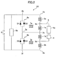
- Fig. 2 is a schematic circuit diagram of the active shield superconducting electromagnet apparatus 22 according to a first embodiment of the present invention.
- the superconducting electromagnet apparatus 22 comprises a main switching circuit wherein a first main coil 1a and a second main coil 1b which have the same excitation directions of magnetic field, a first shield coil 2a and a second shield coil 2b which have the excitation direction reverse to that of the first main coil 1a, and a first superconducting persistent current switch 5b are connected in series.
- the main switching circuit includes a closed circuit wherein the first superconducting persistent current switch 5b - node 3h - node 3a - the first shield coil 2a - node 3b - the first main coil 1a - node 3c - the second main coil 1b - node 3d - the second shield coil 2b - node 3e - node 3f - the first superconducting persistent current switch 5b are connected in the above order, and the first superconducting persistent current switch 5b can open/close this closed circuit.
- An excitation power supply terminals 9 is connected to the first superconducting persistent current switch 5b in parallel. Further, all wires of the main switching circuit are made of superconducting wires.
- the first main coil 1a and the second main coil 1b generate a magnetic field that has a high intensity and a greater homogeneity than a predetermined level in the imaging region 16 (see Fig. 1 ).
- the first shield coil 2a and the second shield coil 2b allow a current to flow in the direction reverse to that of the first main coil 1a and the second main coil 1b, and suppress a leakage of magnetic field, which is generated from the first main coil 1a and the second main coil 1b, out of the vacuum vessel 13 (see Fig. 1 ).
- These first main coil 1a, second main coil 1b, first shield coil 2a, and second shield coil 2b are connected in series as shown in Fig. 2 .
- Each of these first main coil 1a, second main coil 1b, first shield coil 2a, and second shield coil 2b may comprise a plurality of coils.
- the superconducting electromagnet apparatus 22 comprises a bypass circuit 6 wherein a superconducting fault current limiter 4 which is changed to a normal conducting state to limit a current flow when a value of current is greater than a pre-determined value, and a second superconducting persistent current switch 5a are connected in series. All of wires of the bypass circuit 6 are also made of superconducting wires.
- the bypass circuit 6 is connected to a series circuit of the first main coil 1a and the second main coil 1b, or a series circuit (not shown) of the first shield coil 2a and the second shield coil 2b, in parallel. As a result, a sub switching circuit is made up.
- the sub switching circuit is a closed circuit wherein the second superconducting persistent current switch 5a - the superconducting fault current limiter 4 - node 3d - the second main coil 1b - node 3c - the first main coil 1a - node 3b - the second superconducting persistent current switch 5a are connected in the above order, and the second superconducting persistent current switch 5a can open/close this closed circuit.
- the superconducting electromagnet apparatus 22 comprises a first closed circuit 7a and a second closed circuit 7b.
- the first closed circuit 7a is made up by connecting the first main coil 1a, the first shield coil 2a, and a first quench protection circuit 8a, through which a current does not flow in the absence of potential difference between both ends of which, and through which a current flows in the presence of potential difference between both ends of which, in series. More concretely, first closed circuit 7a is made up by connecting the first main coil 1a - node 3c - node 3g - the first quench protection circuit 8a - node 3h - node 3a - the first shield coil 2a - node 3b - the first main coil 1a in the above order.
- the first quench protection circuit 8a comprises a parallel circuit which includes anti-parallel first and second diodes D1 and D2.
- the second closed circuit 7b is made up by connecting the second main coil 1b, the second shield coil 2b, and a second quench protection circuit 8b, through which a current does not flow in the absence of potential difference between both ends of which, and through which a current flows in the presence of potential difference between both ends of which, in series. More concretely, second closed circuit 7b is made up by connecting the second main coil 1b - node 3d - the second shield coil 2b - node 3e - node 3f - the second quench protection circuit 8b - node 3g - node 3c - second main coil 1b in the above order.
- the second quench protection circuit 8b comprises a parallel circuit which includes anti-parallel third and fourth diodes D3 and D4.
- the first superconducting persistent current switch 5b and the second superconducting persistent current switch 5a are turned off, and a power supply (not shown), which is connected to the excitation power supply terminals 9, supplies power to the first main coil 1a, the second main coil 1b, the first shield coil 2a, and the second shield coil 2b until a rated current flows through the main switching circuit. After the rated current flows, the first superconducting persistent current switch 5b is turned on. Next, the power supply is removed from the excitation power supply terminals 9. The superconducting electromagnet apparatus 22 is changed to a persistent current mode wherein a persistent current flows. Further, an electrical resistance (including a wire resistance) of the main switching circuit, through which the persistent current flows, becomes zero (0).
- the second superconducting persistent current switch 5a is turned on.
- an electrical resistance (including a wire resistance) of the bypass circuit 6 becomes zero (0), the persistent current flowing through the main switching circuit does not flow into the bypass circuit 6. This is because each of the first main coil 1a, the second main coil 1b, the first shield coil 2a, and the second shield coil 2b tends to allow a constant persistent current to flow. If a part of the persistent current flows through the bypass circuit 6, at any one of the first main coil 1a, the second main coil 1b, the first shield coil 2a, and the second shield coil 2b, the persistent current reduces, and it becomes impossible for the constant persistent current to flow. Because of this, the persistent current flowing through the main switching circuit does not flow into the bypass circuit 6.
- first main coil 1a, the second main coil 1b, the first shield coil 2a, and the second shield coil 2b are quenched in the superconducting electromagnet apparatus 22.
- first quench protection circuit 8a and the second quench protection circuit 8b are omitted so that the first closed circuit 7a and the second closed circuit 7b are not made up. Due to the mechanical disturbance, etc., when heat is generated at a part of the first main coil 1a, the second main coil 1b, the first shield coil 2a, and the second shield coil 2b, the superconductivity around the portion breaks down, an electrical resistance R appears as shown in Fig. 3A , and a persistent current I0 causes Joule heat.
- this normal conducting region is expanded, two kinds of voltages described below are generated at each of the coils 1a, 1b, 2a, and 2b.
- the resistance voltage VR at any of coils 1a, 1b, 2a, and 2b increases largely, thereby decreasing the persistent current I0 and increasing the induced voltage VL. Because the induced voltage VL is superimposed on the resistance voltage VR, as shown in Fig. 3B , a voltage V0 generated at each of coils 1a, 1b, 2a, and 2b provides a maximum voltage V0p after a certain time from quench generation.
- this maximum voltage V0p By generation of this maximum voltage V0p, a voltage of several thousand volts is applied to the bypass circuit 6. This changes the superconducting fault current limiter 4 to a normal conducting state immediately to generate a resistance which limits an excessive current.
- the superconducting fault current limiter 4 may be burned out because a several amperes of current flows when the voltage of several thousand volts is applied. Therefore, it is necessary to reduce the current flowing through this bypass circuit 6 to a fraction of its original value, and further to reduce the maximum voltage V0p applied to the bypass circuit 6 to a fraction of its original value.
- first quench protection circuit 8a and the second quench protection circuit 8b are added so that the first closed circuit 7a and the second closed circuit 7b are made up in the superconducting electromagnet apparatus 22.
- heat is generated at a part of the coils 1a, 1b, 2a, and 2b, the superconductivity breaks down, an electrical resistance R appears, and a resistance voltage VR given by the product of the electrical resistance R and the persistent current I0 is generated.
- a resistance voltage VR which is no less than on-voltage (from a few tenth to a few volts)
- a current flows through any one of the diodes D1-D4. Namely, the current flows through the first closed circuit 7a and the second closed circuit 7b. This current is divided from the persistent current. Since each of the first closed circuit 7a and the second closed circuit 7b comprises two coils, the inductance L of the circuit is smaller than that of the main switching circuit having four coils connected in series.
- the first closed circuit 7a since a pair of the first main coil 1a and the first shield coil 2a, winding directions of which are reversed, are used in the first closed circuit 7a, a mutual inductance between the first main coil 1a and the first shield coil 2a can be reduced. That is, the inductances cancel each other, and a sum of inductances L can be reduced.
- the second closed circuit 7b since a pair of the second main coil 1b and the second shield coil 2b, winding directions of which are reversed, are used, a mutual inductance between the second main coil 1b and the second shield coil 2b can be reduced. That is, the inductances cancel each other, and a sum of inductances L can be reduced.
- the inductance L Since the inductance L is reduced, it becomes difficult for an electromotive force to be generated in the coils 1a, 1b, 2a, and 2b to resist a current decay, and the decay of the persistent current is no longer prevented. And, as shown in a persistent current I1 in Fig. 3A , the persistent current I1 can be decayed faster than the persistent current I0.
- the values of maximum voltages V0p and V1p depend on the relationship between a growth rate of resistance R and decay rates of persistent currents I0 and I1.
- the active shield superconducting electromagnet apparatus 22 capable of suppressing a large current flowing through the superconducting fault current limiter 4 although a quench phenomenon occurs in the main coils 1a, 1b, or the shield coils 2a, 2b, is provided.
- Fig. 4 is a schematic circuit diagram of the active shield superconducting electromagnet apparatus 22 according to a second embodiment of the present invention.
- the superconducting electromagnet apparatus 22 according to the second embodiment of the present invention differs from the superconducting electromagnet apparatus 22 of the first embodiment in that the first main coil 1a, the second main coil 1b, the first shield coil 2a, and the second shield coil 2b are connected in series in order of the first shield coil 2a, the second main coil 1b, the first main coil 1a, and the second shield coil 2b.
- coils are arranged on the Z-axis in order of the first shield coil 2a, the first main coil 1a, the second main coil 1b, and the second shield coil 2b from up to down as shown in Fig. 1 .
- the first closed circuit 7a is made up to include the second main coil 1b instead of the first main coil 1a.
- the second closed circuit 7b is made up to include the first main coil 1a instead of the second main coil 1b.
- the first closed circuit 7a includes the first shield coil 2a - node 3b - the second main coil 1b - node 3c - node 3g - the first quench protection circuit 8a - node 3h - node 3a - the first shield coil 2a which are connected in the above order.
- the second closed circuit 7b includes the second shield coil 2b - node 3e - node 3f - the second quench protection circuit 8b - node 3g - node 3c - the first main coil 1a - node 3d - the second shield coil 2b which are connected in the above order.
- a quench-back heater is used.
- coils are moved toward each other to provide a current changing by an electromagnetic induction, or a current changing is provided in the coils of a series circuit (of the first closed circuit 7a, and the second closed circuit 7b) wherein coils are connected in series, and wherein the current is common, thereby a magnetic field to which the coils are exposed is changed, an alternating-current loss is generated in superconducting wires of unquenched coils, and allow the quench phenomenon to propagate and to be induced.
- the quench-back heater since the quench-back heater is not used, it is possible to reduce the cost, and since any foreign matter is not attached to the superconducting coil, it is possible to improve the reliability.
- the electromagnetic coupling between the coils is determined by sizes of coils and arrangement (distance between coils). In case of MRI system, etc., since the arrangement of coils is strictly determined to realize a homogeneous magnetic field, it is impossible to change sizes and arrangement of coils only to change the electromagnetic coupling. On the other hand, it is possible to determine which of coils is included in the first closed circuit 7a or the second closed circuit 7b only with change in wiring between coils, without change in sizes and arrangement of coils.
- a pair of the first shield coil 2a and the first main coil 1a are spaced apart from a pair of the second main coil 1b and the second shield coil 2b, and the electromagnetic coupling between them is weak.
- the first shield coil 2a is spatially closed to the first main coil 1a, and the electromagnetic coupling is strong.
- the second main coil 1b is spatially closed to the second shield coil 2b, and the electromagnetic coupling is strong.
- the first closed circuit 7a is made up to include the first shield coil 2a and the second main coil 1b.
- the second closed circuit 7b is made up to include the first main coil 1a and the second shield coil 2b.
- the quench phenomenon is allowed to propagate and to be induced in the second main coil 1b by the above described alternating-current loss. Further, the quench in the first shield coil 2a is allowed to propagate to the first main coil 1a having strong electromagnetically coupling to the first shield coil 2a. In the second shield coil 2b, the quench phenomenon is allowed to propagate via two routes, namely, a current changing in the second closed circuit 7b caused by the quenched first main coil 1a, and an electromagnetic coupling caused by the quenched second main coil 1b.
- the quench phenomenon is allowed to propagate over all of the coils 1a, 1b, 2a, and 2b.
- the electrical resistance increases in all of the coils 1a, 1b, 2a, and 2b to promote the decay of the persistent current, the resistance voltage of the coil at which quench begins can be suppressed, and the current flowing through the superconducting fault current limiter 4 in the bypass circuit 6 can be reduced.
- Fig. 5 is a schematic circuit diagram of the active shield superconducting electromagnet apparatus 22 according to a third embodiment of the present invention. As shown in Fig. 5 , the superconducting electromagnet apparatus 22 according to the third embodiment of the present invention differs from the superconducting electromagnet apparatus 22 of the first embodiment in that quench protection circuits 8a-8d are individually provided for the first shield coil 2a, the first main coil 1a, the second main coil 1b, and the second shield coil 2b.
- the first closed circuit 7a is made up. More concretely, the first closed circuit 7a is made up by connecting the first shield coil 2a - node 3b - node 3j - the first quench protection circuit 8a - node 3h - node 3a - the first shield coil 2a in the above order.
- third closed circuit 7c is made up by connecting the first main coil 1a - node 3c - node 3g - the third quench protection circuit 8c - node 3j - node 3b - the first main coil 1a in the above order.
- the third quench protection circuit 8c comprises a parallel circuit which includes anti-parallel fifth and sixth diodes D5 and D6.
- a fourth closed circuit 7d is made up. More concretely, fourth closed circuit 7d is made up by connecting the second main coil 1b - node 3d - node 3i - the fourth quench protection circuit 8d - node 3g - node 3c - the second main coil 1b in the above order. Further, the fourth quench protection circuit 8d comprises a parallel circuit which includes anti-parallel seventh and eighth diodes D7 and D8.
- second closed circuit 7b is made up by connecting the second shield coil 2b - node 3e - node 3f - the second quench protection circuit 8b - node 3i - node 3d - the second shield coil 2b in the above order.
- the inductance L per one of the closed circuits 7a-7d decreases, and at the beginning of quench, the persistent current can be decayed easily. Also, since a potential difference between both ends of each of the coils 1a, 1b, 2a, and 2b is determined by the on-voltage of the diodes D1-D8 respectively, the potential difference between both ends is no more than 10 volts. Even if one coil is quenched, a current changing occurs in a closed circuit which includes the coil. However, it is impossible to allow this current changing to propagate to any other coil. Therefore, it becomes difficult for a quench phenomenon to be propagated between coils by a current changing. However, there is no change in the electromagnetic coupling between coils. Therefore, like the first embodiment, it is possible to allow a quench phenomenon to propagate by electromagnetic coupling.
- Fig. 6 is a schematic circuit diagram of the active shield superconducting electromagnet apparatus 22 according to a fourth embodiment of the present invention.
- the superconducting electromagnet apparatus 22 according to the fourth embodiment of the present invention differs from the superconducting electromagnet apparatus 22 of the third embodiment in that electrical resistors 17a and 17b, which serve as quench-back heaters, are provided between node 3b and node 3j, and electrical resistors 17c and 17d, which serve as quench-back heaters, are provided between node 3d and node 3i.
- the electrical resistor 17a is arranged in the vicinity of the first shield coil 2a in thermal contact with it.
- the electrical resistor 17b is arranged in the vicinity of the first main coil 1a in thermal contact with it.
- the electrical resistor 17c is arranged in the vicinity of the second main coil 1b in thermal contact with it.
- the electrical resistor 17d is arranged in the vicinity of the second shield coil 2b in thermal contact with it.
- the electrical resistors 17a and 17b are newly added between node 3b and node 3j. Further, with respect to the electrical resistors 17a and 17b, a current does not flow through in the absence of potential difference between both ends, and a current flows through in the presence of potential difference between both ends. This characteristic is the same as that of the first quench protection circuit 8a. From this, it may be considered that the first quench protection circuit 8a comprises only a pair of bidirectional diodes D1 and D2, and the electrical resistors 17a and 17b. Further, first quench protection circuit 8a comprise the electrical resistors 17a and 17b, and may dispense with a pair of bidirectional diodes D1 and D2. More concretely, node 3h and node 3j may be short-circuited.
- a third closed circuit 7c the electrical resistors 17a and 17b are newly added between node 3b and node 3j.
- the electrical resistors 17a and 17b serve in the first closed circuit 7a and the third closed circuit 7c.
- the third quench protection circuit 8c comprises a pair of bidirectional diodes D5 and D6, and the electrical resistors 17a and 17b.
- the third quench protection circuit 8c comprises the electrical resistors 17a and 17b, and may dispense with a pair of bidirectional diodes D5 and D6. More concretely, node 3j and node 3g may be short-circuited.
- the electrical resistors 17c and 17d are newly added between node 3d and node 3i.
- the fourth quench protection circuit 8d comprises a pair of bidirectional diodes D7 and D8, and the electrical resistors 17c and 17d.
- the fourth quench protection circuit 8d comprises the electrical resistors 17c and 17d, and may dispense with a pair of bidirectional diodes D7 and D8. More concretely, node 3g and node 3i may be short-circuited.
- the electrical resistors 17c and 17d are newly added between node 3d and node 3i.
- the electrical resistors 17c and 17d serve in the fourth closed circuit 7d and the second closed circuit 7b.
- the second quench protection circuit 8b comprises a pair of bidirectional diodes D3 and D4, and the electrical resistors 17c and 17d.
- second quench protection circuit 8b comprises the electrical resistors 17c and 17d, and may dispense with a pair of bidirectional diodes D3 and D4. More concretely, node 3i and node 3f may be short-circuited.
- the behavior of electrical resistors 17a-17d in the case wherein the coils 1a, 1b, 2a, and 2b are quenched will be explained.
- the case wherein the first shield coil 2a begins to be quenched is considered.
- the resistance voltage is generated between node 3a and node 3b, both ends of the first shield coil 2a. Since this resistance voltage is applied between node 3j and node 3h, both ends of a pair of bidirectional diodes, either diode D1 or diode D2 will be turned on, and an on-current will flow through. As a result, a circulating current flows through the first closed circuit 7a.
- the electrical resistors 17a and 17b Since this circulating current flows through the electrical resistors 17a and 17b, the electrical resistors 17a and 17b generate heat. Since the electrical resistor 17a heats a large portion of the first shield coil 2a, it can allow a quench phenomenon generated at a localized portion of the first shield coil 2a to propagate extensively. Since the electrical resistor 17b heats a large portion of the first main coil 1a, it can allow a quench phenomenon to be generated extensively depending on heating. This provides that it is possible to allow a quench phenomenon to propagate from the first shield coil 2a to the first main coil 1a.
- an induced electromotive force is generated by the electromagnetic coupling with the first main coil 1a (mutual inductance).
- voltage is generated between node 3i and node 3g, both ends of a pair of bidirectional diodes D7 and D8, either diode D7 or diode D8 will be turned on, and an on-current will flow through.
- a circulating current flows through the fourth closed circuit 7d. Since this circulating current flows through the electrical resistors 17c and 17d, the electrical resistors 17c and 17d generate heat. Since the electrical resistor 17c heats a large portion of the second main coil 1b, it can allow a quench phenomenon to be generated extensively depending on heating.
- Fig. 7 is a schematic circuit diagram of the active shield superconducting electromagnet apparatus 22 according to a fifth embodiment of the present invention.
- the superconducting electromagnet apparatus 22 according to the fifth embodiment of the present invention differs from the superconducting electromagnet apparatus 22 of the fourth embodiment in that relative to the large size of the second main coil 1b, the electrical resistor 17b is arranged in the vicinity of the second main coil 1b (not the first main coil 1a) in thermal contact with it. Also, it differs that relative to the large size of the first main coil 1a, the electrical resistor 17c is arranged in the vicinity of the first main coil 1a (not the second main coil 1b) in thermal contact with it.
- the electromagnetic coupling (mutual inductance) is weak
- a current flows through a pair of bidirectional diodes D1 and D2 by voltage generated at the first shield coil 2a, and this current circulates through the first closed circuit 7a.
- the electrical resistors 17a and 17b generate heat.
- the electrical resistor 17a heats the first shield coil 2a
- the electrical resistor 17b heats the second main coil 1b.
- the second main coil 1b is quenched by this heating. As a result, a quench phenomenon is allowed to propagate from the first shield coil 2a to the second main coil 1b.
- a quench phenomenon is allowed to propagate from the first shield coil 2a to the first main coil 1a which is electromagnetically coupled to the first shield coil 2a strongly. Further, in the second shield coil 2b, the quench phenomenon is allowed to propagate via two routes, namely, heat of the electrical resistor 17d generated by a current circulation in the fourth closed circuit 7d caused by the quenched second main coil 1b, and an electromagnetic coupling caused by the quenched second main coil 1b. As described above, the quench phenomenon is allowed to propagate in all of the coils 1a, 1b, 2a, and 2b.
- Fig. 8 is a schematic circuit diagram of the active shield superconducting electromagnet apparatus 22 according to a sixth embodiment of the present invention.
- the superconducting electromagnet apparatus 22 according to the sixth embodiment of the present invention differs from the superconducting electromagnet apparatus 22 of the first embodiment (see Fig. 2 ) in that node 3ga and node 3gb are formed at a location which corresponds to node 3g in Fig. 2 .
- Node 3ga is directly connected to the first quench protection circuit 8a
- node 3gb is directly connected to the second quench protection circuit 8b.
- node 3c and node 3g are short-circuited in Fig. 2 , it differs in that electrical resistors 17a and 17b are provided between node 3c and node 3ga to serve as a quench-back heater, and electrical resistors 17c and 17d are provided between node 3c and node 3gb to serve as a quench-back heater in Fig. 8 .
- the electrical resistor 17a is arranged in the vicinity of the second shield coil 2b in thermal contact with it.
- the electrical resistor 17b is arranged in the vicinity of the second main coil 1b in thermal contact with it.
- the electrical resistor 17c is arranged in the vicinity of the first main coil 1a in thermal contact with it.
- the electrical resistor 17d is arranged in the vicinity of the first shield coil 2a in thermal contact with it.
- the electrical resistors 17a and 17b are newly added between node 3c and node 3ga. Further, with respect to the electrical resistors 17a and 17b, a current does not flow through in the absence of potential difference between both ends, and a current flows through in the presence of potential difference between both ends. This characteristic is the same as that of the first quench protection circuit 8a. From this, it may be considered that the first quench protection circuit 8a comprises a pair of bidirectional diodes D1 and D2, and the electrical resistors 17a and 17b. Further, the first quench protection circuit 8a comprises the electrical resistors 17a and 17b, and may dispense with a pair of bidirectional diodes D1 and D2. More concretely, node 3h and node 3ga may be short-circuited.
- the electrical resistors 17c and 17d are newly added between node 3c and node 3gb.
- the second quench protection circuit 8b also comprises a pair of bidirectional diodes D3 and D4, and the electrical resistors 17c and 17d.
- the second quench protection circuit 8b comprises the electrical resistors 17c and 17d, and may dispense with a pair of bidirectional diodes D3 and D4. More concretely, node 3gb and node 3f may be short-circuited.
- the behavior of electrical resistors 17a-17d in the case wherein the coils 1a, 1b, 2a, and 2b are quenched will be explained.
- the case wherein the first shield coil 2a begins to be quenched is considered.
- the resistance voltage is generated between node 3a and node 3b, both ends of the first shield coil 2a. Since this resistance voltage is applied between node 3ga and node 3h, both ends of a pair of bidirectional diodes, either diode D1 or diode D2 will be turned on, and an on-current will flow through. As a result, a circulating current flows through the first closed circuit 7a.
- the electrical resistors 17a and 17b Since this circulating current flows through the electrical resistors 17a and 17b, the electrical resistors 17a and 17b generate heat. Since the electrical resistor 17a heats a large portion of the second shield coil 2b, it can allow a quench phenomenon to be generated extensively depending on heating. Since the electrical resistor 17b heats a large portion of the second main coil 1b, it can allow a quench phenomenon to be generated extensively depending on heating. This provides that it is possible to allow a quench phenomenon to propagate from the first shield coil 2a to the second main coil 1b and the second shield coil 2b.
- the quench phenomenon is allowed to propagate via three routes, namely, an electromagnetic coupling caused by the quenched first shield coil 2a, a current changing in the first closed circuit 7a caused by the quenched first shield coil 2a, and heat of the electrical resistor 17c generated by a current circulation in the second closed circuit 7b caused by the quenched second main coil 1b and the quenched second shield coil 2b.
- the quench phenomenon is allowed to propagate to all of the coils 1a, 1b, 2a, and 2b.
- node 3ga and node 3gb may be short-circuited.
- a serial connection of the electrical resistor 17a and the electrical resistor 17b, and a serial connection of the electrical resistor 17c and the electrical resistor 17d are connected in parallel. It is considered that the electrical resistor 17c and the electrical resistor 17d are commonly used in both the first closed circuit 7a and the second closed circuit 7b. And, the quench phenomenon is allowed to propagate to all of the coils 1a, 1b, 2a, and 2b via heat of the electrical resistors 17a-17d.
- main central axes of a pair of opposed main coils 1a and 1b are oriented in the vertical direction, they may be oriented in the horizontal direction.
- the Z-axis is oriented in the horizontal direction, the direction of magnetic field is in the horizontal direction, the direction of access to the imaging region 16 for a patient matches the direction of magnetic field, and a cylindrical magnet can be used.
Landscapes
- Physics & Mathematics (AREA)
- Condensed Matter Physics & Semiconductors (AREA)
- General Physics & Mathematics (AREA)
- Health & Medical Sciences (AREA)
- Epidemiology (AREA)
- Electromagnetism (AREA)
- Engineering & Computer Science (AREA)
- Power Engineering (AREA)
- Magnetic Resonance Imaging Apparatus (AREA)
Applications Claiming Priority (1)
| Application Number | Priority Date | Filing Date | Title |
|---|---|---|---|
| JP2007204909A JP4542573B2 (ja) | 2007-08-07 | 2007-08-07 | アクティブシールド型の超電導電磁石装置および磁気共鳴イメージング装置 |
Publications (3)
| Publication Number | Publication Date |
|---|---|
| EP2026083A2 true EP2026083A2 (fr) | 2009-02-18 |
| EP2026083A3 EP2026083A3 (fr) | 2009-09-30 |
| EP2026083B1 EP2026083B1 (fr) | 2016-10-05 |
Family
ID=39941899
Family Applications (1)
| Application Number | Title | Priority Date | Filing Date |
|---|---|---|---|
| EP08252646.8A Active EP2026083B1 (fr) | 2007-08-07 | 2008-08-07 | Appareil doté d'un électro-aimant supraconducteur à bouclier actif pour IRM avec protection améliorée lors d'une transition de l'état supraconducteur à l'état normal |
Country Status (4)
| Country | Link |
|---|---|
| US (1) | US7990661B2 (fr) |
| EP (1) | EP2026083B1 (fr) |
| JP (1) | JP4542573B2 (fr) |
| CN (1) | CN101409128B (fr) |
Cited By (2)
| Publication number | Priority date | Publication date | Assignee | Title |
|---|---|---|---|---|
| US8583201B2 (en) | 2010-09-21 | 2013-11-12 | General Electric Company | Quench protection circuit for superconducting magnet coils |
| GB2545998A (en) * | 2015-12-28 | 2017-07-05 | Bruker Biospin Gmbh | Superconducting magnet coil system |
Families Citing this family (12)
| Publication number | Priority date | Publication date | Assignee | Title |
|---|---|---|---|---|
| US7969697B2 (en) * | 2008-04-22 | 2011-06-28 | Exar Corporation | Low-voltage CMOS space-efficient 15 KV ESD protection for common-mode high-voltage receivers |
| JP5322780B2 (ja) * | 2009-06-01 | 2013-10-23 | 三菱電機株式会社 | 超電導マグネット装置 |
| GB2471325B (en) * | 2009-06-26 | 2011-05-18 | Siemens Magnet Technology Ltd | Quench energy dissipation for superconducting magnets |
| US8542015B2 (en) * | 2011-01-19 | 2013-09-24 | General Electric Company | Apparatus and method for protecting a magnetic resonance imaging magnet during quench |
| JP2013208188A (ja) * | 2012-03-30 | 2013-10-10 | Hitachi Medical Corp | 超電導磁石装置、超電導コイルの保護方法、および、磁気共鳴画像装置 |
| US9240681B2 (en) | 2012-12-27 | 2016-01-19 | General Electric Company | Superconducting coil system and methods of assembling the same |
| CN104124033B (zh) * | 2013-04-26 | 2017-04-19 | 深圳联影医疗科技有限公司 | 超导磁体电路及磁体锻炼方法 |
| KR101821439B1 (ko) * | 2013-11-15 | 2018-03-08 | 엘에스산전 주식회사 | 한류기 |
| JP6215345B2 (ja) * | 2013-11-15 | 2017-10-18 | 株式会社日立製作所 | 超電導磁石 |
| JP6601797B2 (ja) * | 2015-10-16 | 2019-11-06 | 国立研究開発法人理化学研究所 | 超伝導磁石装置とその異常時の電流低下抑制方法 |
| CN116779276A (zh) * | 2018-10-19 | 2023-09-19 | 皇家飞利浦有限公司 | 用于低铜-超导导线线圈的快速失超保护 |
| CN113679351B (zh) * | 2021-09-02 | 2023-06-09 | 河南大学第一附属医院 | 一种适用于野外环境的磁共振急救仓 |
Citations (6)
| Publication number | Priority date | Publication date | Assignee | Title |
|---|---|---|---|---|
| US3474294A (en) | 1966-04-19 | 1969-10-21 | Varian Associates | Superconductive magnet protected by forward and backward conducting diode pairs |
| JPS6437814A (en) | 1987-07-17 | 1989-02-08 | Siemens Ag | Superconducting magnet of nuclear magnetic resonance tomographer |
| US5660903A (en) | 1992-08-11 | 1997-08-26 | E. Khashoggi Industries | Sheets having a highly inorganically filled organic polymer matrix |
| US6147844A (en) | 1998-12-30 | 2000-11-14 | General Electric Company | Quench protection for persistant superconducting magnets for magnetic resonance imaging |
| US20040027737A1 (en) | 2001-09-25 | 2004-02-12 | Minfeng Xu | Balanced quench protection circuit |
| US20040263165A1 (en) | 2003-06-27 | 2004-12-30 | Weijun Shen | Methods and apparatus for imaging systems |
Family Cites Families (10)
| Publication number | Priority date | Publication date | Assignee | Title |
|---|---|---|---|---|
| JPS4945632A (fr) | 1972-09-01 | 1974-05-01 | ||
| GB2298282B (en) * | 1995-02-23 | 1999-08-25 | Elscint Ltd | Quench protection for actively shielded magnets |
| US5650903A (en) * | 1995-11-30 | 1997-07-22 | General Electric Company | Superconducting-magnet electrical circuit having voltage and quench protection |
| JP3731231B2 (ja) | 1995-11-30 | 2006-01-05 | 株式会社日立メディコ | 超電導磁石装置 |
| DE19930412C1 (de) * | 1999-07-02 | 2000-12-21 | Bruker Ag Faellanden | Aktiv abgeschirmte supraleitende Magnetanordnung mit Feldstörungskompensation |
| DE19940694C1 (de) * | 1999-08-27 | 2001-07-26 | Bruker Ag Faellanden | Aktiv abgeschirmte supraleitende Magnetanordnung mit Z·2·-Shim |
| US7116535B2 (en) * | 2004-04-16 | 2006-10-03 | General Electric Company | Methods and apparatus for protecting an MR imaging system |
| JP4933034B2 (ja) * | 2004-06-10 | 2012-05-16 | 株式会社日立製作所 | 超伝導コイルの保護装置、nmr装置及びmri装置 |
| JP4319602B2 (ja) * | 2004-08-31 | 2009-08-26 | 株式会社日立製作所 | クエンチ保護回路を備える超電導マグネット装置 |
| JP4404021B2 (ja) * | 2005-06-30 | 2010-01-27 | 株式会社日立製作所 | Mri用超電導磁石 |
-
2007
- 2007-08-07 JP JP2007204909A patent/JP4542573B2/ja active Active
-
2008
- 2008-08-06 US US12/186,618 patent/US7990661B2/en not_active Expired - Fee Related
- 2008-08-06 CN CN2008101313385A patent/CN101409128B/zh not_active Expired - Fee Related
- 2008-08-07 EP EP08252646.8A patent/EP2026083B1/fr active Active
Patent Citations (6)
| Publication number | Priority date | Publication date | Assignee | Title |
|---|---|---|---|---|
| US3474294A (en) | 1966-04-19 | 1969-10-21 | Varian Associates | Superconductive magnet protected by forward and backward conducting diode pairs |
| JPS6437814A (en) | 1987-07-17 | 1989-02-08 | Siemens Ag | Superconducting magnet of nuclear magnetic resonance tomographer |
| US5660903A (en) | 1992-08-11 | 1997-08-26 | E. Khashoggi Industries | Sheets having a highly inorganically filled organic polymer matrix |
| US6147844A (en) | 1998-12-30 | 2000-11-14 | General Electric Company | Quench protection for persistant superconducting magnets for magnetic resonance imaging |
| US20040027737A1 (en) | 2001-09-25 | 2004-02-12 | Minfeng Xu | Balanced quench protection circuit |
| US20040263165A1 (en) | 2003-06-27 | 2004-12-30 | Weijun Shen | Methods and apparatus for imaging systems |
Cited By (4)
| Publication number | Priority date | Publication date | Assignee | Title |
|---|---|---|---|---|
| US8583201B2 (en) | 2010-09-21 | 2013-11-12 | General Electric Company | Quench protection circuit for superconducting magnet coils |
| GB2545998A (en) * | 2015-12-28 | 2017-07-05 | Bruker Biospin Gmbh | Superconducting magnet coil system |
| US10128030B2 (en) | 2015-12-28 | 2018-11-13 | Bruker Biospin Gmbh | Superconducting magnet coil system |
| GB2545998B (en) * | 2015-12-28 | 2019-09-11 | Bruker Biospin Gmbh | Superconducting magnet coil system |
Also Published As
| Publication number | Publication date |
|---|---|
| EP2026083B1 (fr) | 2016-10-05 |
| US7990661B2 (en) | 2011-08-02 |
| EP2026083A3 (fr) | 2009-09-30 |
| JP2009039183A (ja) | 2009-02-26 |
| CN101409128B (zh) | 2012-01-25 |
| CN101409128A (zh) | 2009-04-15 |
| JP4542573B2 (ja) | 2010-09-15 |
| US20090040664A1 (en) | 2009-02-12 |
Similar Documents
| Publication | Publication Date | Title |
|---|---|---|
| EP2026083B1 (fr) | Appareil doté d'un électro-aimant supraconducteur à bouclier actif pour IRM avec protection améliorée lors d'une transition de l'état supraconducteur à l'état normal | |
| JP2609295B2 (ja) | 核磁気共鳴断層像装置の超伝導磁石 | |
| US7876100B2 (en) | Method and apparatus for actively controlling quench protection of a superconducting magnet | |
| US6646836B2 (en) | Superconducting magnet apparatus in persistent mode | |
| US6563316B2 (en) | Magnet arrangement comprising an actively shielded superconducting magnet coil system and an additional current path for stray field suppression in case of a quench | |
| US8350568B2 (en) | Nuclear magnetic resonance apparatus | |
| US20040027737A1 (en) | Balanced quench protection circuit | |
| JPH04287903A (ja) | 磁石組立体 | |
| US7116535B2 (en) | Methods and apparatus for protecting an MR imaging system | |
| US20130106545A1 (en) | Single switch dump resistor ladder network for magnet quench protection | |
| JP3447090B2 (ja) | 超電導性磁石を有する磁気共鳴装置 | |
| JP2001060510A (ja) | 磁場擾乱に対する補償が改善されたアクティブ・シールド超伝導磁石装置及び超伝導磁石装置の設計と最適化のための方法 | |
| US9671479B2 (en) | Method and apparatus for shimming a superconducting magnet | |
| CN111292914A (zh) | 用于给hts匀场装置充电的方法和磁体布置系统 | |
| US7064550B2 (en) | Method and apparatus for field drift compensation of a superconducting magnet | |
| US20090237076A1 (en) | Magnetic resonance imaging apparatus, a method and a computer program for compensation of a field drift of the main magnet | |
| JP2658532B2 (ja) | 超電導マグネット装置 | |
| JP2000068118A (ja) | 永久電流超電導磁石装置 | |
| JPH11102807A (ja) | 超電導マグネットのクエンチ保護回路 | |
| JP4699293B2 (ja) | 超電導マグネット | |
| JPS63304608A (ja) | 核スピン断層撮影装置の磁石系 | |
| JP2016051833A (ja) | 超電導電磁石装置 | |
| JPH03155105A (ja) | 超電導磁石の励磁方法 | |
| JP2011000368A (ja) | 磁場発生装置 | |
| JP2003068519A (ja) | 超電導磁石装置、および、超電導磁石装置での磁場安定化方法 |
Legal Events
| Date | Code | Title | Description |
|---|---|---|---|
| PUAI | Public reference made under article 153(3) epc to a published international application that has entered the european phase |
Free format text: ORIGINAL CODE: 0009012 |
|
| 17P | Request for examination filed |
Effective date: 20080826 |
|
| AK | Designated contracting states |
Kind code of ref document: A2 Designated state(s): AT BE BG CH CY CZ DE DK EE ES FI FR GB GR HR HU IE IS IT LI LT LU LV MC MT NL NO PL PT RO SE SI SK TR |
|
| AX | Request for extension of the european patent |
Extension state: AL BA MK RS |
|
| PUAL | Search report despatched |
Free format text: ORIGINAL CODE: 0009013 |
|
| AK | Designated contracting states |
Kind code of ref document: A3 Designated state(s): AT BE BG CH CY CZ DE DK EE ES FI FR GB GR HR HU IE IS IT LI LT LU LV MC MT NL NO PL PT RO SE SI SK TR |
|
| AX | Request for extension of the european patent |
Extension state: AL BA MK RS |
|
| RIC1 | Information provided on ipc code assigned before grant |
Ipc: G01R 33/3815 20060101AFI20081114BHEP Ipc: H01F 6/02 20060101ALI20090825BHEP Ipc: H02H 7/00 20060101ALI20090825BHEP Ipc: G01R 33/38 20060101ALI20090825BHEP Ipc: G01R 33/421 20060101ALI20090825BHEP |
|
| 17Q | First examination report despatched |
Effective date: 20100412 |
|
| AKX | Designation fees paid |
Designated state(s): AT BE BG CH CY CZ DE DK EE ES FI FR GB GR HR HU IE IS IT LI LT LU LV MC MT NL NO PL PT RO SE SI SK TR |
|
| GRAP | Despatch of communication of intention to grant a patent |
Free format text: ORIGINAL CODE: EPIDOSNIGR1 |
|
| RIC1 | Information provided on ipc code assigned before grant |
Ipc: G01R 33/28 20060101ALN20160201BHEP Ipc: G01R 33/38 20060101ALI20160201BHEP Ipc: H01F 6/02 20060101ALI20160201BHEP Ipc: G01R 33/421 20060101ALI20160201BHEP Ipc: H02H 7/00 20060101ALI20160201BHEP Ipc: G01R 33/3815 20060101AFI20160201BHEP |
|
| INTG | Intention to grant announced |
Effective date: 20160217 |
|
| GRAR | Information related to intention to grant a patent recorded |
Free format text: ORIGINAL CODE: EPIDOSNIGR71 |
|
| GRAS | Grant fee paid |
Free format text: ORIGINAL CODE: EPIDOSNIGR3 |
|
| RIC1 | Information provided on ipc code assigned before grant |
Ipc: G01R 33/3815 20060101AFI20160706BHEP Ipc: G01R 33/38 20060101ALI20160706BHEP Ipc: H01F 6/02 20060101ALI20160706BHEP Ipc: G01R 33/28 20060101ALN20160706BHEP Ipc: H02H 7/00 20060101ALI20160706BHEP Ipc: G01R 33/421 20060101ALI20160706BHEP |
|
| INTG | Intention to grant announced |
Effective date: 20160712 |
|
| GRAA | (expected) grant |
Free format text: ORIGINAL CODE: 0009210 |
|
| AK | Designated contracting states |
Kind code of ref document: B1 Designated state(s): AT BE BG CH CY CZ DE DK EE ES FI FR GB GR HR HU IE IS IT LI LT LU LV MC MT NL NO PL PT RO SE SI SK TR |
|
| REG | Reference to a national code |
Ref country code: GB Ref legal event code: FG4D |
|
| REG | Reference to a national code |
Ref country code: CH Ref legal event code: EP |
|
| REG | Reference to a national code |
Ref country code: AT Ref legal event code: REF Ref document number: 835093 Country of ref document: AT Kind code of ref document: T Effective date: 20161015 |
|
| REG | Reference to a national code |
Ref country code: IE Ref legal event code: FG4D |
|
| REG | Reference to a national code |
Ref country code: DE Ref legal event code: R096 Ref document number: 602008046621 Country of ref document: DE |
|
| REG | Reference to a national code |
Ref country code: NL Ref legal event code: MP Effective date: 20161005 |
|
| REG | Reference to a national code |
Ref country code: LT Ref legal event code: MG4D |
|
| PG25 | Lapsed in a contracting state [announced via postgrant information from national office to epo] |
Ref country code: LV Free format text: LAPSE BECAUSE OF FAILURE TO SUBMIT A TRANSLATION OF THE DESCRIPTION OR TO PAY THE FEE WITHIN THE PRESCRIBED TIME-LIMIT Effective date: 20161005 |
|
| REG | Reference to a national code |
Ref country code: AT Ref legal event code: MK05 Ref document number: 835093 Country of ref document: AT Kind code of ref document: T Effective date: 20161005 |
|
| PG25 | Lapsed in a contracting state [announced via postgrant information from national office to epo] |
Ref country code: LT Free format text: LAPSE BECAUSE OF FAILURE TO SUBMIT A TRANSLATION OF THE DESCRIPTION OR TO PAY THE FEE WITHIN THE PRESCRIBED TIME-LIMIT Effective date: 20161005 Ref country code: SE Free format text: LAPSE BECAUSE OF FAILURE TO SUBMIT A TRANSLATION OF THE DESCRIPTION OR TO PAY THE FEE WITHIN THE PRESCRIBED TIME-LIMIT Effective date: 20161005 Ref country code: GR Free format text: LAPSE BECAUSE OF FAILURE TO SUBMIT A TRANSLATION OF THE DESCRIPTION OR TO PAY THE FEE WITHIN THE PRESCRIBED TIME-LIMIT Effective date: 20170106 Ref country code: NO Free format text: LAPSE BECAUSE OF FAILURE TO SUBMIT A TRANSLATION OF THE DESCRIPTION OR TO PAY THE FEE WITHIN THE PRESCRIBED TIME-LIMIT Effective date: 20170105 |
|
| PG25 | Lapsed in a contracting state [announced via postgrant information from national office to epo] |
Ref country code: PT Free format text: LAPSE BECAUSE OF FAILURE TO SUBMIT A TRANSLATION OF THE DESCRIPTION OR TO PAY THE FEE WITHIN THE PRESCRIBED TIME-LIMIT Effective date: 20170206 Ref country code: FI Free format text: LAPSE BECAUSE OF FAILURE TO SUBMIT A TRANSLATION OF THE DESCRIPTION OR TO PAY THE FEE WITHIN THE PRESCRIBED TIME-LIMIT Effective date: 20161005 Ref country code: PL Free format text: LAPSE BECAUSE OF FAILURE TO SUBMIT A TRANSLATION OF THE DESCRIPTION OR TO PAY THE FEE WITHIN THE PRESCRIBED TIME-LIMIT Effective date: 20161005 Ref country code: BE Free format text: LAPSE BECAUSE OF FAILURE TO SUBMIT A TRANSLATION OF THE DESCRIPTION OR TO PAY THE FEE WITHIN THE PRESCRIBED TIME-LIMIT Effective date: 20161005 Ref country code: HR Free format text: LAPSE BECAUSE OF FAILURE TO SUBMIT A TRANSLATION OF THE DESCRIPTION OR TO PAY THE FEE WITHIN THE PRESCRIBED TIME-LIMIT Effective date: 20161005 Ref country code: NL Free format text: LAPSE BECAUSE OF FAILURE TO SUBMIT A TRANSLATION OF THE DESCRIPTION OR TO PAY THE FEE WITHIN THE PRESCRIBED TIME-LIMIT Effective date: 20161005 Ref country code: ES Free format text: LAPSE BECAUSE OF FAILURE TO SUBMIT A TRANSLATION OF THE DESCRIPTION OR TO PAY THE FEE WITHIN THE PRESCRIBED TIME-LIMIT Effective date: 20161005 Ref country code: AT Free format text: LAPSE BECAUSE OF FAILURE TO SUBMIT A TRANSLATION OF THE DESCRIPTION OR TO PAY THE FEE WITHIN THE PRESCRIBED TIME-LIMIT Effective date: 20161005 Ref country code: IS Free format text: LAPSE BECAUSE OF FAILURE TO SUBMIT A TRANSLATION OF THE DESCRIPTION OR TO PAY THE FEE WITHIN THE PRESCRIBED TIME-LIMIT Effective date: 20170205 |
|
| REG | Reference to a national code |
Ref country code: DE Ref legal event code: R097 Ref document number: 602008046621 Country of ref document: DE |
|
| PG25 | Lapsed in a contracting state [announced via postgrant information from national office to epo] |
Ref country code: RO Free format text: LAPSE BECAUSE OF FAILURE TO SUBMIT A TRANSLATION OF THE DESCRIPTION OR TO PAY THE FEE WITHIN THE PRESCRIBED TIME-LIMIT Effective date: 20161005 Ref country code: DK Free format text: LAPSE BECAUSE OF FAILURE TO SUBMIT A TRANSLATION OF THE DESCRIPTION OR TO PAY THE FEE WITHIN THE PRESCRIBED TIME-LIMIT Effective date: 20161005 Ref country code: EE Free format text: LAPSE BECAUSE OF FAILURE TO SUBMIT A TRANSLATION OF THE DESCRIPTION OR TO PAY THE FEE WITHIN THE PRESCRIBED TIME-LIMIT Effective date: 20161005 Ref country code: SK Free format text: LAPSE BECAUSE OF FAILURE TO SUBMIT A TRANSLATION OF THE DESCRIPTION OR TO PAY THE FEE WITHIN THE PRESCRIBED TIME-LIMIT Effective date: 20161005 Ref country code: CZ Free format text: LAPSE BECAUSE OF FAILURE TO SUBMIT A TRANSLATION OF THE DESCRIPTION OR TO PAY THE FEE WITHIN THE PRESCRIBED TIME-LIMIT Effective date: 20161005 |
|
| PLBE | No opposition filed within time limit |
Free format text: ORIGINAL CODE: 0009261 |
|
| STAA | Information on the status of an ep patent application or granted ep patent |
Free format text: STATUS: NO OPPOSITION FILED WITHIN TIME LIMIT |
|
| PG25 | Lapsed in a contracting state [announced via postgrant information from national office to epo] |
Ref country code: IT Free format text: LAPSE BECAUSE OF FAILURE TO SUBMIT A TRANSLATION OF THE DESCRIPTION OR TO PAY THE FEE WITHIN THE PRESCRIBED TIME-LIMIT Effective date: 20161005 Ref country code: BG Free format text: LAPSE BECAUSE OF FAILURE TO SUBMIT A TRANSLATION OF THE DESCRIPTION OR TO PAY THE FEE WITHIN THE PRESCRIBED TIME-LIMIT Effective date: 20170105 |
|
| 26N | No opposition filed |
Effective date: 20170706 |
|
| PG25 | Lapsed in a contracting state [announced via postgrant information from national office to epo] |
Ref country code: SI Free format text: LAPSE BECAUSE OF FAILURE TO SUBMIT A TRANSLATION OF THE DESCRIPTION OR TO PAY THE FEE WITHIN THE PRESCRIBED TIME-LIMIT Effective date: 20161005 |
|
| REG | Reference to a national code |
Ref country code: CH Ref legal event code: PL |
|
| PG25 | Lapsed in a contracting state [announced via postgrant information from national office to epo] |
Ref country code: MC Free format text: LAPSE BECAUSE OF FAILURE TO SUBMIT A TRANSLATION OF THE DESCRIPTION OR TO PAY THE FEE WITHIN THE PRESCRIBED TIME-LIMIT Effective date: 20161005 |
|
| PG25 | Lapsed in a contracting state [announced via postgrant information from national office to epo] |
Ref country code: CH Free format text: LAPSE BECAUSE OF NON-PAYMENT OF DUE FEES Effective date: 20170831 Ref country code: LI Free format text: LAPSE BECAUSE OF NON-PAYMENT OF DUE FEES Effective date: 20170831 |
|
| REG | Reference to a national code |
Ref country code: FR Ref legal event code: ST Effective date: 20180430 |
|
| REG | Reference to a national code |
Ref country code: IE Ref legal event code: MM4A |
|
| PG25 | Lapsed in a contracting state [announced via postgrant information from national office to epo] |
Ref country code: LU Free format text: LAPSE BECAUSE OF NON-PAYMENT OF DUE FEES Effective date: 20170807 |
|
| PG25 | Lapsed in a contracting state [announced via postgrant information from national office to epo] |
Ref country code: IE Free format text: LAPSE BECAUSE OF NON-PAYMENT OF DUE FEES Effective date: 20170807 |
|
| PG25 | Lapsed in a contracting state [announced via postgrant information from national office to epo] |
Ref country code: FR Free format text: LAPSE BECAUSE OF NON-PAYMENT OF DUE FEES Effective date: 20170831 |
|
| PG25 | Lapsed in a contracting state [announced via postgrant information from national office to epo] |
Ref country code: MT Free format text: LAPSE BECAUSE OF NON-PAYMENT OF DUE FEES Effective date: 20170807 |
|
| PG25 | Lapsed in a contracting state [announced via postgrant information from national office to epo] |
Ref country code: HU Free format text: LAPSE BECAUSE OF FAILURE TO SUBMIT A TRANSLATION OF THE DESCRIPTION OR TO PAY THE FEE WITHIN THE PRESCRIBED TIME-LIMIT; INVALID AB INITIO Effective date: 20080807 |
|
| REG | Reference to a national code |
Ref country code: DE Ref legal event code: R082 Ref document number: 602008046621 Country of ref document: DE Representative=s name: MEWBURN ELLIS LLP, DE |
|
| PG25 | Lapsed in a contracting state [announced via postgrant information from national office to epo] |
Ref country code: CY Free format text: LAPSE BECAUSE OF NON-PAYMENT OF DUE FEES Effective date: 20161005 |
|
| PG25 | Lapsed in a contracting state [announced via postgrant information from national office to epo] |
Ref country code: TR Free format text: LAPSE BECAUSE OF FAILURE TO SUBMIT A TRANSLATION OF THE DESCRIPTION OR TO PAY THE FEE WITHIN THE PRESCRIBED TIME-LIMIT Effective date: 20161005 |
|
| REG | Reference to a national code |
Ref country code: GB Ref legal event code: 732E Free format text: REGISTERED BETWEEN 20240711 AND 20240717 |
|
| REG | Reference to a national code |
Ref country code: DE Ref legal event code: R081 Ref document number: 602008046621 Country of ref document: DE Owner name: HITACHI HIGH-TECH CORPORATION, JP Free format text: FORMER OWNER: HITACHI, LTD., TOKYO, JP |
|
| PGFP | Annual fee paid to national office [announced via postgrant information from national office to epo] |
Ref country code: DE Payment date: 20250702 Year of fee payment: 18 |
|
| PGFP | Annual fee paid to national office [announced via postgrant information from national office to epo] |
Ref country code: GB Payment date: 20250703 Year of fee payment: 18 |