EP2026084A2 - Parallele MRI mit einer Einzelspule - Google Patents
Parallele MRI mit einer Einzelspule Download PDFInfo
- Publication number
- EP2026084A2 EP2026084A2 EP08252643A EP08252643A EP2026084A2 EP 2026084 A2 EP2026084 A2 EP 2026084A2 EP 08252643 A EP08252643 A EP 08252643A EP 08252643 A EP08252643 A EP 08252643A EP 2026084 A2 EP2026084 A2 EP 2026084A2
- Authority
- EP
- European Patent Office
- Prior art keywords
- image
- lines
- data
- pixel
- mri system
- Prior art date
- Legal status (The legal status is an assumption and is not a legal conclusion. Google has not performed a legal analysis and makes no representation as to the accuracy of the status listed.)
- Withdrawn
Links
- 238000003384 imaging method Methods 0.000 title claims abstract description 64
- 230000008859 change Effects 0.000 claims abstract description 41
- 239000002131 composite material Substances 0.000 claims abstract description 28
- 238000000034 method Methods 0.000 claims abstract description 25
- 230000000747 cardiac effect Effects 0.000 claims description 37
- 230000000750 progressive effect Effects 0.000 claims description 4
- 238000013459 approach Methods 0.000 description 45
- 238000002595 magnetic resonance imaging Methods 0.000 description 38
- 230000002829 reductive effect Effects 0.000 description 25
- 238000005070 sampling Methods 0.000 description 25
- 230000003068 static effect Effects 0.000 description 16
- 239000002872 contrast media Substances 0.000 description 10
- 239000011159 matrix material Substances 0.000 description 9
- 230000008569 process Effects 0.000 description 9
- 230000008901 benefit Effects 0.000 description 8
- 230000002123 temporal effect Effects 0.000 description 7
- 238000002583 angiography Methods 0.000 description 6
- 238000012545 processing Methods 0.000 description 6
- 230000035945 sensitivity Effects 0.000 description 6
- 238000012935 Averaging Methods 0.000 description 4
- 238000010586 diagram Methods 0.000 description 3
- 238000002610 neuroimaging Methods 0.000 description 3
- 238000004088 simulation Methods 0.000 description 3
- 210000004556 brain Anatomy 0.000 description 2
- 230000002526 effect on cardiovascular system Effects 0.000 description 2
- 230000036961 partial effect Effects 0.000 description 2
- 230000009467 reduction Effects 0.000 description 2
- 230000029058 respiratory gaseous exchange Effects 0.000 description 2
- 238000000926 separation method Methods 0.000 description 2
- 230000009466 transformation Effects 0.000 description 2
- 230000003321 amplification Effects 0.000 description 1
- 210000000709 aorta Anatomy 0.000 description 1
- 239000008280 blood Substances 0.000 description 1
- 210000004369 blood Anatomy 0.000 description 1
- 210000004204 blood vessel Anatomy 0.000 description 1
- 210000000746 body region Anatomy 0.000 description 1
- 230000001010 compromised effect Effects 0.000 description 1
- 239000000356 contaminant Substances 0.000 description 1
- 238000011109 contamination Methods 0.000 description 1
- 230000001419 dependent effect Effects 0.000 description 1
- 230000000694 effects Effects 0.000 description 1
- 238000005516 engineering process Methods 0.000 description 1
- 238000000105 evaporative light scattering detection Methods 0.000 description 1
- 238000001914 filtration Methods 0.000 description 1
- 238000002599 functional magnetic resonance imaging Methods 0.000 description 1
- 230000006872 improvement Effects 0.000 description 1
- 230000000670 limiting effect Effects 0.000 description 1
- 230000003211 malignant effect Effects 0.000 description 1
- 238000005259 measurement Methods 0.000 description 1
- 239000000203 mixture Substances 0.000 description 1
- 230000004048 modification Effects 0.000 description 1
- 238000012986 modification Methods 0.000 description 1
- 238000003199 nucleic acid amplification method Methods 0.000 description 1
- 230000002572 peristaltic effect Effects 0.000 description 1
- 230000035479 physiological effects, processes and functions Effects 0.000 description 1
- 238000012805 post-processing Methods 0.000 description 1
- 238000009877 rendering Methods 0.000 description 1
- 230000000241 respiratory effect Effects 0.000 description 1
- 210000000115 thoracic cavity Anatomy 0.000 description 1
- 210000000779 thoracic wall Anatomy 0.000 description 1
- 230000001960 triggered effect Effects 0.000 description 1
- 230000002792 vascular Effects 0.000 description 1
- 210000005166 vasculature Anatomy 0.000 description 1
Images


Classifications
-
- A—HUMAN NECESSITIES
- A61—MEDICAL OR VETERINARY SCIENCE; HYGIENE
- A61B—DIAGNOSIS; SURGERY; IDENTIFICATION
- A61B5/00—Measuring for diagnostic purposes; Identification of persons
- A61B5/05—Detecting, measuring or recording for diagnosis by means of electric currents or magnetic fields; Measuring using microwaves or radio waves
- A61B5/055—Detecting, measuring or recording for diagnosis by means of electric currents or magnetic fields; Measuring using microwaves or radio waves involving electronic [EMR] or nuclear [NMR] magnetic resonance, e.g. magnetic resonance imaging
-
- G—PHYSICS
- G01—MEASURING; TESTING
- G01R—MEASURING ELECTRIC VARIABLES; MEASURING MAGNETIC VARIABLES
- G01R33/00—Arrangements or instruments for measuring magnetic variables
- G01R33/20—Arrangements or instruments for measuring magnetic variables involving magnetic resonance
- G01R33/44—Arrangements or instruments for measuring magnetic variables involving magnetic resonance using nuclear magnetic resonance [NMR]
- G01R33/48—NMR imaging systems
- G01R33/54—Signal processing systems, e.g. using pulse sequences ; Generation or control of pulse sequences; Operator console
- G01R33/56—Image enhancement or correction, e.g. subtraction or averaging techniques, e.g. improvement of signal-to-noise ratio and resolution
- G01R33/561—Image enhancement or correction, e.g. subtraction or averaging techniques, e.g. improvement of signal-to-noise ratio and resolution by reduction of the scanning time, i.e. fast acquiring systems, e.g. using echo-planar pulse sequences
- G01R33/5611—Parallel magnetic resonance imaging, e.g. sensitivity encoding [SENSE], simultaneous acquisition of spatial harmonics [SMASH], unaliasing by Fourier encoding of the overlaps using the temporal dimension [UNFOLD], k-t-broad-use linear acquisition speed-up technique [k-t-BLAST], k-t-SENSE
-
- G—PHYSICS
- G01—MEASURING; TESTING
- G01R—MEASURING ELECTRIC VARIABLES; MEASURING MAGNETIC VARIABLES
- G01R33/00—Arrangements or instruments for measuring magnetic variables
- G01R33/20—Arrangements or instruments for measuring magnetic variables involving magnetic resonance
- G01R33/44—Arrangements or instruments for measuring magnetic variables involving magnetic resonance using nuclear magnetic resonance [NMR]
- G01R33/48—NMR imaging systems
- G01R33/4818—MR characterised by data acquisition along a specific k-space trajectory or by the temporal order of k-space coverage, e.g. centric or segmented coverage of k-space
- G01R33/482—MR characterised by data acquisition along a specific k-space trajectory or by the temporal order of k-space coverage, e.g. centric or segmented coverage of k-space using a Cartesian trajectory
-
- G—PHYSICS
- G01—MEASURING; TESTING
- G01R—MEASURING ELECTRIC VARIABLES; MEASURING MAGNETIC VARIABLES
- G01R33/00—Arrangements or instruments for measuring magnetic variables
- G01R33/20—Arrangements or instruments for measuring magnetic variables involving magnetic resonance
- G01R33/44—Arrangements or instruments for measuring magnetic variables involving magnetic resonance using nuclear magnetic resonance [NMR]
- G01R33/48—NMR imaging systems
- G01R33/54—Signal processing systems, e.g. using pulse sequences ; Generation or control of pulse sequences; Operator console
- G01R33/56—Image enhancement or correction, e.g. subtraction or averaging techniques, e.g. improvement of signal-to-noise ratio and resolution
- G01R33/561—Image enhancement or correction, e.g. subtraction or averaging techniques, e.g. improvement of signal-to-noise ratio and resolution by reduction of the scanning time, i.e. fast acquiring systems, e.g. using echo-planar pulse sequences
- G01R33/5619—Image enhancement or correction, e.g. subtraction or averaging techniques, e.g. improvement of signal-to-noise ratio and resolution by reduction of the scanning time, i.e. fast acquiring systems, e.g. using echo-planar pulse sequences by temporal sharing of data, e.g. keyhole, block regional interpolation scheme for k-Space [BRISK]
-
- G—PHYSICS
- G01—MEASURING; TESTING
- G01R—MEASURING ELECTRIC VARIABLES; MEASURING MAGNETIC VARIABLES
- G01R33/00—Arrangements or instruments for measuring magnetic variables
- G01R33/20—Arrangements or instruments for measuring magnetic variables involving magnetic resonance
- G01R33/44—Arrangements or instruments for measuring magnetic variables involving magnetic resonance using nuclear magnetic resonance [NMR]
- G01R33/48—NMR imaging systems
- G01R33/54—Signal processing systems, e.g. using pulse sequences ; Generation or control of pulse sequences; Operator console
- G01R33/56—Image enhancement or correction, e.g. subtraction or averaging techniques, e.g. improvement of signal-to-noise ratio and resolution
- G01R33/563—Image enhancement or correction, e.g. subtraction or averaging techniques, e.g. improvement of signal-to-noise ratio and resolution of moving material, e.g. flow contrast angiography
- G01R33/56308—Characterization of motion or flow; Dynamic imaging
Definitions
- the present invention is related to the 3D imaging of an object in change using an MRI. More specifically, the present invention is related to the 3D imaging of an object in change using an MRI with a single coil element by itself or independent of other single coil elements of the MRI which produce corresponding images that are combined to form a composite image of the object.
- the Reduced Field of View approach assumes that only a part of the field of view is dynamic, and that the fold over information can be removed by subtracting that information from a previously acquired fully resolved image.
- the SMASH and SENSE approaches are related in that they use the sensitivity profiles of separate receiver coils to remove the folded over data. They rely on using two or more receiver coils, each with a distinctly different sensitivity profile to the body section being imaged. Essentially, the folded over data are removed for images in pairs (or higher combinations) of coils with each image pair having different sensitivity characteristics as determined by the coils.
- the SMASH approach performs this disentangling operation in the k-space domain, while the SENSE approach performs this operation in the image domain.
- the present invention pertains to an imaging apparatus for an object in change.
- the apparatus comprises an MRI system having a computer, a first channel and at least a second channel which produce corresponding images of the object in change, preferably using alternate lines of k-space.
- the computer combining the individual images into a composite image of the object.
- the MRI system acquiring alternate lines of temporally resolved data.
- the present invention pertains to an imaging apparatus for an object in change.
- the apparatus comprises an MRI system having a computer, and at least a first channel which produces an image of the object in change from data acquired in k-space domain in a density of at least 1/2 that required to satisfy the Nyquist criteria.
- the present invention pertains to a method for imaging an object in change.
- the method comprises the steps of producing an individual image of the object in change with a first channel of an MRI system, preferably using alternate lines of k-space.
- the present invention pertains to an imaging apparatus for an object in change.
- the apparatus comprises an MRI system having a computer, a first channel which produces images of the object in change using alternate lines of k-space applied along each of the two phase encoding directions.
- the computer combining the individual images into a composite 3D image of the object.
- the MRI system acquiring alternate lines of temporally resolved data along each of the phase encoding directions, such that at any one time point at least 25% of full data is acquired.
- Full data being defined as k-space data that satisfies the Nyquist sampling criteria.
- the present invention pertains to a method for imaging an object in change.
- the method comprises the steps of producing an individual image of the object in change with a first channel of an MRI system using alternate lines of k-space applied for each phase encoding direction.
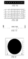
- Figure 1 shows a fully resolved k-space data set that conforms to the Nyquist sampling criteria.
- Figure 2 shows the corresponding MR image generated from the k-space data set of Figure 1 .
- Figure 3 shows a k-space data set with every other line omitted, i.e. a half data set.
- Figure 4 shows the corresponding MR image generated from the k-space data set shown in Figure 3 , illustrating a half image fold over artifact.
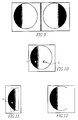
- Figure 5 shows one frame of a cardiac image series seen using only one coil element.
- Figure 6 is a block diagram of a self-referencing process.
- Figure 7A represents the fully sampled k-space series.
- Figure 7B represents how the sparsely sampled k-space matrix data are acquired at each point in the cardiac cycle.
- Figure 7C shows where images are to be represented throughout the cardiac cycle.
- Figure 8 shows the last two frames of the acquired k-space data are combined such that the even and odd lines of k-space are correctly positioned in the matrix.
- Figure 9 shows the single frame of the fully resolved image is imaged at different intensities from each of the receiver coil elements.
- Figure 10 shows, for the single frame of the fully resolved image for each coil element the ratio map is formed from pixels that would overlap in a folded over image.
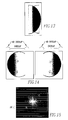
- Figure 11 shows from each of the folded over images for one particular coil element.
- Figure 12 shows, for each coil element, the unfolding operation works best for the pixels closest to the coil location.
- Figure 13 shows a separate folded over image is available from each coil element.
- Figure 14 shows, for opposite coil elements, the unfolded images have opposite edges set to zero.
- Figure 15 shows a schematic of the density of sampling of k-space lines that satisfy the Nyquist sampling criteria.
- Figure 16 is a block diagram of the imaging apparatus of the present invention.
- Figures 17A-17D show a simulation of single coil parallel imaging (17A and 17C) and corresponding single coil parallel images (17B and 17D).
- Figure 18 shows a typical cardiovascular image featuring the heart.
- FIG. 19 shows a typical configuration for 3D imaging, in which a coil element is positioned primarily over one quadrant of the image (a single 2D slice from the 3D data set is represented) and that in 3D imaging, there are two phase encoding axes, termed “Horizontal” and “Vertical” here.
- Figures 20A and 20B (3D) show that when a sparse sampling factor of 2 is applied to both of the phase encoding axes (i.e. "Horizontal” and “Vertical") then the field of view (FOV) is reduced to one quarter of the full image, and pixels from four quadrants superimpose in the reduced FOV image.
- a sparse sampling factor of 2 is applied to both of the phase encoding axes (i.e. "Horizontal” and “Vertical) then the field of view (FOV) is reduced to one quarter of the full image, and pixels from four quadrants superimpose in the reduced FOV image.
- Figure 21 shows that in a 3D acquisition, when acquiring alternate phase encoding lines along the two phase encoding axes, that the order of lines can be cycled between even and odd lines, and between "Horizontal” and “Vertical” phase encoding axes, such that four successive data sets can be combined to produce a fully sampled 3D data set.
- Figures 22A, 22B and 22C (3D) show that the folded over data set for one time frame is unfolded by the ratio based pixel assignment of the current invention, and is used in this example to only populate the intensities of the primary quadrant, i.e. the image quadrant in which the receiver coil element produces the most signal.
- the apparatus 10 comprises an MRI system 12 having a computer 14, a first channel 16 and at least a second channel 18 which produce corresponding images of the object in change, preferably using alternate lines of k-space.
- the computer 14 combines the individual images into a composite image of the object.
- the MRI system acquires alternate lines of temporally resolved data.
- the MRI system 12 preferably requires at least one frame of temporally resolved data at full resolution.
- each channel includes a coil element 20 and a signal receiver 22, for each channel, retains image data corresponding to a region closest to the coil element 20, the region including at least 50% of the data.
- the at least one frame of temporally resolved data at full resolution is preferably acquired over two time frames, which may be consecutive or temporally distributed.
- the present invention pertains to an imaging apparatus 10 for an object in change.
- the apparatus 10 comprises an MRI system 12 having a computer 14, a first channel 16 which produces images of the object in change using alternate lines of k-space applied along each of two phase encoding directions.
- the computer 14 combines the individual images into a composite 3D image of the object.
- the MRI system 12 acquiring alternate lines of temporally resolved data along each of the phase encoding directions, such that at any one time point at least 25% of full (satisfying Nyquist sampling criteria) data are acquired.
- the MRI system 12 can acquire even lined datasets only of even lines during even-numbered time points in a series and odd lined data points only of odd lines during odd numbered time points in the series. Alternatively, at each time point the MRI system 12 acquires alternate lines along each phase encoding direction including all even lines or all odd lines and additionally a contiguous number of lines at each time point near the center of k-space (e.g. 10% of the data required to satisfying Nyquist sampling criteria for the fully resolved data set).
- each channel 16, 18 includes a coil element 20 and a signal receiver 22 which retains image data corresponding to a region closest to the coil element 20.
- the region includes at least 25% of the data.
- the MRI system 12 preferably acquires the alternate lines in a progressive manner along each of two phase encoding axes such that a full dataset having all even and all odd lined datasets can be combined from every four consecutive time frames. Alternately, if the central region of k-space is acquired at each time point, then this data is used to produce a correctly ordered image that is of low resolution.
- the low resolution image does not suffer from signal aliasing, but renders images without sharp features, showing only the general intensity distribution without incorporating fine image detail.
- the even lined datasets can correspond to even-numbered cardiac phases and odd lined datasets correspond to odd-numbered cardiac phases.
- similar alternate lined datasets are acquired at each time point.
- the computer 14 forms a ratio map for each coil element 20 separately using the corresponding fully solved image.
- the ratio map for an individual channel corresponds to an intensity ratio of pixels that would overlap in an approximately 25% folded over image.
- the computer 14 preferably uses the ratio map to distribute pixel intensity only to the primary pixel closest to the coil element 20.
- the present invention pertains to a method for imaging an object in change.
- the method comprises the steps of producing an individual image of the object in change with a first channel 16 of an MRI system 12 using alternate lines of k-space applied for each phase encoding direction.
- step to acquiring only one fully resolved 2D frame instead acquire alternate lines in the manner such that only even lines are acquired during alternate cardiac phases (e.g. acquire only even line during even numbered cardiac phases) and only acquire odd lines during the interleaved cardiac phases (e.g. acquire odd lines during odd numbered cardiac phases).
- the alternating even and odd lined data sets can be progressively combined for adjacent time point data sets to produce a dynamic series of fully resolved images, albeit, images that exhibit motion artifact and distortion due to being formed from data spanning two cardiac phase intervals.
- an alternative step to acquiring only one fully resolved 3D data set is to acquire alternate lines in a progressive manner along each of the two phase encoding axes, 31, such that a full data set (i.e. all even and all odd lines) can be compiled from every 4 consecutive time frames.
- the individual image from each coil is imaged at different intensities to form a fully resolved image.
- the computer 14 preferably forms a ratio map for each coil separately using the corresponding fully resolved image(s).
- the ratio map for an individual channel corresponds to an intensity ratio of pixels that would overlap in an approximately 50% folded over image.
- the computer 14 preferably uses the ratio map to distribute pixel intensity between a first pixel closest to the coil and a second pixel more remote to the coil than the first pixel.
- the ratio maps can be formed in the following manner, which reduces the influence of motion artifacts:
- the individual image from each coil element is imaged at different intensities to form a fully resolved image or image series, 29.
- the computer 14 preferably forms a ratio map for each coil separately using the corresponding fully resolved image.
- the ratio map for an individual channel corresponds to an intensity ratio of the set of four pixels that would overlap in an approximately 25% folded over image,30, with the fold over direction being applied to each of the two phase encoding directions used in 3D imaging.
- the ratio map is established in the following manner: 1) the numerator is formed by the primary pixel intensity (i.e. the pixel in the contiguous volume closest to the imaging coil element), and 2) the denominator is formed by combining by addition the three corresponding pixels that would overlap the primary pixel).
- the computer 14 preferably uses the ratio map to distribute pixel intensity to the primary pixel closest to the coil element 32.
- R is the ratio value suitable for 3D data (i.e. ratio of primary pixel to the sum of the three remote pixels) and C is the observed intensity in the folded over image, 32.
- Other pixels remote from the primary coil element quadrant are not assigned in the typical case, since there is not generally a strong means of differentiating between them.
- it is feasible to assign intensities to each of the three pixels based on the formula PI r R r ⁇ C - closest pixel intensity / R r + 1 .
- PI r is the pixel intensity for remote pixel "r”
- R r is the ratio value for the primary pixel and the remote pixel "r”
- C is the observed intensity in the folded over image
- “Closest pixel intensity” is the value assigned to the primary pixel.
- the computer 14 preferably forms the composite image by setting pixels of the individual image of the first channel 16 with no overlap with the individual image of the second channel 18 to the value of the pixel of the first individual image.
- the computer 14 forms the composite image with composite pixels with non-zero values of the individual images that overlap equal to the square root of the sum of the squares of the individual pixels which overlap.
- the present invention pertains to an imaging apparatus 10 for an object in change.
- the apparatus 10 comprises an MRI system 12 having a computer 14, and at least a first channel 16 which produce an image of the object in change from data acquired in k-space domain in a density of at least 2/3 and preferably at least 1/2 that required to satisfy the Nyquist criteria in the 2D case.
- the present invention pertains to a method for imaging an object in change.
- the method comprises the steps of producing an individual image of the object in change with a first channel 16 of an MRI system 12, preferably using alternate lines of k-space.
- the producing the individual image of the object in change with the first channel 16 step includes the step of acquiring alternate lines of temporally resolved data.
- the producing the individual image of the object in change with the first channel 16 step preferably includes the step of acquiring at least one frame of temporally resolved data at full resolution.
- each channel includes a coil element 20 and a signal receiver 22, and there is the step of retaining image data corresponding to a region closest to the coil element 20, the region including at least 50% of the data, for each channel in the 2D case.
- the step of acquiring at least one frame of temporally resolved data at full resolution step preferably includes the step of acquiring at least one frame of temporally resolved data at full resolution over two time frames, which may be consecutive or temporally distributed.
- the producing the individual image of the object in change with the first channel 16 step includes the step of imaging the individual image with the coil element 20 at different intensities.
- the ratio map forming step includes the step of forming the ratio map for an individual channel corresponding to an intensity ratio of pixels that would overlap in an approximately 50% folded over image.
- the key features of the single coil parallel imaging scheme are:
- the apparatus 10 is an MRI approach to produce dynamic images in a reduced scan time by exploiting the signal intensity profile of an individual coil element 20 of a phased array receiver coil set (the apparatus 10 can work for a single coil or multiple coils).
- the MRI signal data is termed k-space.
- the apparatus 10 samples every other line of k-space for most frames of the dynamic series. In the 2D version, this translates to only acquiring 50% of k-space, and in the 3D version, where there are two independent phase encoding direction, it translates to acquiring 25% of k-space. Additionally, one k-space frame of the series is sampled in its entirety. This can be accomplished by combining data obtained from two or more suitably sampled k-space data sets.
- the technique requires two commonly met conditions: 1) the intensity of the received signal falls off with distance into the body (this signal characteristic is normally present for each separate element of a typical receiver coil system), and 2) the dynamic feature being imaged occupies approximately 50% of the field of view (this is typically met for cardiac and other imaging situations, although this condition does not have to be rigorously met).
- Figure 1 shows a fully resolved k-space data set.
- the corresponding MR image generated from this is shown in Figure 2 .
- Figure 3 shows a k-space data set with every other line omitted, i.e. a half data set.
- the corresponding MR image generated from this is shown in Figure 4 , illustrating a half image fold over artifact.
- the final image is derived from a series of separate receiver coil elements 20 (typically 4, 8 or 16). For each receiver coil element 20 each part of the image is seen with different intensity, depending on how close it is to the receiver coil.
- Figure 5 shows one frame of a cardiac image series seen using only one coil element 20. In this case, the signal is most intense at the chest wall (arrow), and falls off dramatically towards the back of the subject (chevron).
- Figure 18 shows a typical cardiovascular image featuring the heart. In this case, the line represents a region of the image, which corresponds to half of the field of view. This half of the field of view contains the bulk of the image features that exhibit motion, or dynamic changes, from frame to frame.
- the apparatus 10 utilizes these separate observations in the following way:
- the apparatus 10 can be used in MR scanners to reduce the scan time for cardiac imaging, or for any imaging sequence that requires dynamic data, examples include: time resolved magnetic resonance angiography, real-time approaches to monitor interventions and procedures, and time resolved imaging to observe the kinetics of a contrast agent.
- the approach herein can be interpreted as a hybrid between parallel imaging and Reduced Field of View approaches. It incorporates many of the key advantages of the other two classes of rapid imaging approach without suffering many of the key disadvantages.
- data for each of three rapid imaging approaches: 1) Reduced Field of View, 2) parallel imaging, 3) and the current invention are acquired with very similar k-space sampling strategies where alternate lines of k-space are sampled.
- the key feature distinguishing them is related to the image/signal processing routine used to produce the final image, which in turn is governed by the physical principle being exploited.
- the advantages of the current invention it is convenient to consider that conventionally, the image reconstructed from sampling alternate lines of k-space is presented as a folded-over image, i.e.
- the SNR of that region is noticeably reduced.
- the g-factor varies over the whole of the imaged volume, and is dependant on multiple factors. However, it is typical for the g-factor to reach an elevated average value of about 1.2 or higher close to the center of the imaged volume. Further, this central region is typically imaged at a lower SNR compared to the periphery of the body by a factor of about 5:1 (depending on coil element 20 size and body region being imaged). Thus, the central region of the image is typically compromised in SNR even in a full scan, and the additional reduction in SNR resulting from elevation of the g-factor typically makes the increase in noise very noticeable.
- the effective g-factor approaches 1.
- the central region of the image typically contains the heart and vasculature, and thus imaging this region with good SNR often imposes a limiting factor on the acceptable image quality. The higher performance in this region will make the current invention desirable.
- the effective g-factor is less than 1, making the present invention perform in a superior manner to other approaches that acquire a reduced data set.
- This aspect is based on forming a noise reduced version of the ratio map by use of the selective averaging process that contributes to the "max-min” procedure. Whereas the use of an averaged quantity might be thought to introduce temporal blurring into the unfolded images, the ratio map operates on individual data at each time point in the cardiac cycle, and thus the ratio map unfolding procedure does not introduce appreciable blur and manifests as an improvement in the signal to noise ratio.
- the factor A approaches 2.
- the folded over data is removed by a multiplication operation, since the ratio of sensitivity between one pixel and the corresponding folded over pixel is used to assign pixel intensity. Since the operation of multiplication does not propagate noise to the extent that subtraction does, the SNR of the final unfolded image approaches the theoretical limit governed by the sparse sampling factor, i.e. the additional noise factor, A, approaches 1.
- the information required to remove folded over image regions uses the ratio map from opposite halves of an individual coil element 20. Since this ratio map is static, and independent of temporal changes that occur in the body, the unfolded images are not temporally averaged or distorted.
- the Single Coil Parallel Imaging apparatus 10 involves an acquisition and a processing stage.
- the acquisition involves acquiring alternate lines of k-space over a time resolved series, e.g. in cardiac imaging, the time dimension represents time over the cardiac cycle.
- Figures 7A-7C show a schematic of one possible manner in which MRI k-space data can be acquired for the Single Coil Parallel Imaging invention.
- Figure 7A represents the fully sampled k-space series (i.e. each k-space data set would generate an un-folded over image).
- Figure 7C represents where images are to be represented throughout the cardiac cycle, i.e. equally distributed from the start of the cardiac cycle to the end in this example.
- Figure 7B represents how the sparsely sampled k-space matrix data are acquired at each point in the cardiac cycle: from the start of the cycle to the penultimate frame, alternate lines of k-space are sampled (e.g. every even line), while for the last frame, alternate lines are sampled, but in this case correspond to the series of lines omitted in the previous frames (e.g. every odd line).
- the majority of the cardiac phases have only the even k-space lines acquired, and the very last time frame has the odd lines of k-space acquired.
- This example is illustrative of the condition where high temporal resolution is not desired at the end of the cycle (e.g. it is geared towards higher resolution over systole and the beginning of diastole, other variations are possible).
- the last two time frames are combined such that a fully resolved k-space data set is formed, i.e. data from two successive time frames are combined to form a fully resolved image that satisfies the Nyquist sampling criteria, Fig 2 .
- a fully formed image for each of the separate coil elements 20 Consider the case where there are two coil elements 20, one positioned on the right hand side (RHS) of the body and one on the left hand side (LHS).
- Figure 8 shows the last two frames of the acquired k-space data are combined such that the even and odd lines of k-space are correctly positioned in the matrix, and the image produced by Fourier transformation represents a fully resolve, i.e. not folded over, image, represented by the circular feature here.
- two representative coil elements 20 one located on the right hand side of the body (RHS) and one on the left hand side (LHS).
- FIG. 9 shows the single frame of the fully resolved image is imaged at different intensities from each of the receiver coil elements 20. Illustrated here for two coil elements 20 positioned on diametrically opposite sides of the body, where for the coil element 20 on the left hand side, the left hand section of the body is imaged with increased intensity (represented by darker shading in the first panel). For the coil element 20 on the right hand side, the right hand section of the body is imaged with increased intensity (represented by darker shading in the second panel).
- the ratio map is formed using the fully resolved image(s).
- the ratio map corresponds to the intensity ratio of pixels that would overlap in a 50% folded over image.
- Figure 10 shows, for the single frame of the fully resolved image for each coil element 20 (shown here for the coil element 20 on the left hand side of the object) the ratio map is formed from pixels that would overlap in a folded over image, e.g. for pixel 1 and pixel 2 the ratio of pixel intensities is formed.
- the ratio operation is performed for all corresponding pixels and stored in a matrix.
- a separate ratio map is formed for each unfolded over image for each coil element 20. The ratio map only has to occupy half of the image matrix, since it incorporates number from each half of the image.
- each coil element 20 folded over images are formed from the k-space lines sampled at alternate time points, Fig 5 .
- Each pixel contains contributions from two overlapping pixels, the position of each pixel is known from simple geometric considerations already used to form the ratio map.
- the ratio map information is used to distribute the pixel intensity between the two pixels, one pixel closest to the coil element 20 and one pixel more remote from the coil element 20.
- Figure 11 shows from each of the folded over images for one particular coil element 20 (e.g. the left hand coil element 20 in this case), Fourier transform of the k-space matrix results in an image with 50% folded over pixels as indicated.
- the observed intensity e.g. C
- the observed intensity represents the contribution from the pixel nearest the coil element 20 (e.g.
- the unfolding operation generally fails to yield good data in the pixels most remote from the coil.
- Figure 12 shows, for each coil element 20, the unfolding operation works best for the pixels closest to the coil location (e.g. left hand location in this example).
- the pixels furthest from the coil are relatively poorly represented, since they are remote from the coil and are thus acquired at a low signal to noise ratio. In this case, these pixels can be set to zero. In this Figure 12 , these pixels can be set to zero. This is not considered a major limitation, since these pixels are poorly seen even in a fully resolved image, and would typically not be examined using that remote coil element 20.
- the unfolding operation can be performed separately for images obtained from each coil element 20.
- Figure 13 shows a separate folded over image is available from each coil element 20.
- the coil element 20 is located on the right hand side of the body.
- a ratio map for this coil element 20 is formed as for the other coil elements, and folded over pixel elements are assigned to positions closer or further from the coil as for all other coil elements.
- the separate unfolded images can be combined at the final stage to produce an image with conventional appearance.
- the operation of combining images is illustrated in Figure 14 .
- Figure 14 shows, for opposite coil elements, the unfolded images have opposite edges set to zero.
- the data are combined as follows: in regions where pixels with non-zero values overlap, the composite pixel is set to the square root of the sum of the squares of the individual pixels; in pixels where only one coil element 20 contributes, the pixel is set to the value of that one coil element 20.
- the density with which k-space has to be sampled without introducing signal aliasing is governed by the Nyquist sampling criteria.
- Figure 14 illustrates that the separation of k-space lines satisfying the Nyquist criteria.
- Figure 15 shows a schematic of the density of sampling of k-space lines that satisfy the Nyquist sampling criteria. In this case, Fourier transformation of the k-space data will yield an image without signal aliasing.
- a channel represents the combination of receiver coil element 20 signal reception, signal amplification, digitization, filtering, and storage of data in the computer 14 system 12.
- corresponding images from each channel can be combined into a composite image.
- the combination process is not critical, but can be taking the square root of the sum of the squares of individual pixels.
- Figure 6 is a block diagram of self-referencing process.
- phase encoding imaging operation in 3D imaging, two axes are generally encoded by the phase encoding imaging operation, represented here as “Horizontal” and “Vertical” directions.
- the “Measurement” or “Frequency Encoding” direction in this case is represented into the plane of the figure, and is not explicitly represented.
- an individual receiver coil element is positioned such that it is primarily sensitive to pixels in one quadrant.
- quadrant 1 contains the primary pixels (for the coil element shown) and quadrants 2, 3, and 4 represent remote quadrants, with low intensity pixels.
- a series of partial data sets are acquired, such that only every other line corresponding to the "horizontal” and “vertical” phase encoding axes are acquired.
- the series of alternate line acquisitions are cycled through the "Even Horizontal” (EH), “Odd Horizontal” (OH), “Even Vertical” (EV) and “Odd Vertical” (OV), such that four consecutive frames can be combined to compile a composite full 3D data set that spans 4 individual time frames.
- the single coil implementation parallel imaging (SCIPI) for 3D has been largely described in terms of cardiac, time resolved imaging, but is not restricted to this application, and is generally applicable to any time resolved situation.
- SCIPI single coil implementation parallel imaging
- three additional examples of its applicability are given, and show that the invention can be customized to optimize performance in multiple situations.
- the essential features of the invention remain invariant: overlapping pixels in a reduced image matrix are separated and assigned to their correct position, at least in the primary section (e.g. half or quarter of the full image) using information obtained from a single coil element.
- a stimuli is applied periodically and a dynamic MRI series is acquired at multiple time points.
- the dynamic k-space series can be compiled over multiple cycles of the stimuli, allowing k-space to be compiled over an extended time, well beyond a single application of the stimuli.
- the reduced sampling scheme and reconstruction approach of SCIPI can be directly applied to this application, without major modification.
- functional brain imaging it is more typical to use 3D imaging (compared to 2D) and typically only an extremely limited and highly localized region of the brain is activated with other regions of the brain remaining essentially unchanged, providing excellent conditions for application of SCIPI.
- contrast angiography In the case of contrast angiography, a bolus of contrast agent is administered and images are obtained (typically 3D, but sometimes in a 2D thick slice, projective manner) as the contrast agent passes through the vessels in the imaged region.
- images typically 3D, but sometimes in a 2D thick slice, projective manner
- conditions are typically arranged such that, primarily, dynamic changes are related to the passage of the contrast agent without confounding changes in configuration of the body, e.g. respiration is suspended, or a limb is held steady.
- the passage of the contrast agent is generally so rapid that only one 3D data set can typically be acquired under optimal contrast conditions.
- a high degree of co-ordination is required between administration of the contrast agent and acquisition of the MRI data.
- the physiology of the vascular system does not deliver the contrast agent to all vessels of interest at the same time (e.g. a dissected aorta may experience early filling of the true lumen and late filling of the false lumen) making an angiogram at a single time point possibly providing misleading information.
- a dissected aorta may experience early filling of the true lumen and late filling of the false lumen
- angiogram at a single time point possibly providing misleading information.
- the present invention can be applied to image passage of the contrast agent in a reduced time per frame, permitting time resolved angiography to be performed.
- the conditions under which angiography are performed are ideally suited to the current invention, where the major dynamic changes in intensity occur in the blood vessel and surrounding tissue is largely static.
- a potential advantage of the current invention is that dynamic changes such as these can potentially be accommodated, since at each time point, only the data obtained at that time point contributes to the image, providing that the ratio map is adequate.
- the key feature in this case being the manner in which the ratio map is generated.
- the manner of generating the ratio map using the "max-min" operation will likely correctly render image features that are not truly static and without contaminating prior or following frames.
- the dynamic features will be correctly assigned, but in this case, images may suffer increased noise.
- the variant in which the alternate lines are cycled between phase encoding directions over a cycle of four time frames allows generation of a dynamic ratio map, but each frame may have a slightly different level of background intensity related to signal phase changes that occur due to slight differences in the k-space sampling pattern.
- the advantage of this approach is that fine vessel detail will likely be detectable, and if rendering as a maximum intensity projection, the slight differences in background intensity between successive frames will likely not result in distracting intensity level changes.
- the degree to which masses in the body are supplied by blood is used to distinguish features such as composition of the mass and potential for being malignant.
- a contrast agent is administered and a series of time resolved (typically 3D) images are acquired to detect differences in arrival time of the contrast agent in the masses compared to normal tissue.
- the present invention could be used to allow rapid time resolution and be used to increase spatial resolution compared to what is conventionally performed, potentially allowing smaller masses to be routinely detected.
Landscapes
- Physics & Mathematics (AREA)
- Health & Medical Sciences (AREA)
- High Energy & Nuclear Physics (AREA)
- Nuclear Medicine, Radiotherapy & Molecular Imaging (AREA)
- Condensed Matter Physics & Semiconductors (AREA)
- General Physics & Mathematics (AREA)
- Life Sciences & Earth Sciences (AREA)
- General Health & Medical Sciences (AREA)
- Radiology & Medical Imaging (AREA)
- Engineering & Computer Science (AREA)
- Signal Processing (AREA)
- Biophysics (AREA)
- Pathology (AREA)
- Biomedical Technology (AREA)
- Heart & Thoracic Surgery (AREA)
- Medical Informatics (AREA)
- Molecular Biology (AREA)
- Surgery (AREA)
- Animal Behavior & Ethology (AREA)
- Public Health (AREA)
- Veterinary Medicine (AREA)
- Magnetic Resonance Imaging Apparatus (AREA)
Applications Claiming Priority (1)
| Application Number | Priority Date | Filing Date | Title |
|---|---|---|---|
| US11/890,610 US8219176B2 (en) | 2007-03-08 | 2007-08-07 | Single coil parallel imaging |
Publications (2)
| Publication Number | Publication Date |
|---|---|
| EP2026084A2 true EP2026084A2 (de) | 2009-02-18 |
| EP2026084A3 EP2026084A3 (de) | 2010-09-22 |
Family
ID=39864845
Family Applications (1)
| Application Number | Title | Priority Date | Filing Date |
|---|---|---|---|
| EP08252643A Withdrawn EP2026084A3 (de) | 2007-08-07 | 2008-08-06 | Parallele MRI mit einer Einzelspule |
Country Status (3)
| Country | Link |
|---|---|
| US (1) | US8219176B2 (de) |
| EP (1) | EP2026084A3 (de) |
| KR (1) | KR20090014982A (de) |
Families Citing this family (11)
| Publication number | Priority date | Publication date | Assignee | Title |
|---|---|---|---|---|
| JP4464373B2 (ja) * | 2006-07-12 | 2010-05-19 | ジーイー・メディカル・システムズ・グローバル・テクノロジー・カンパニー・エルエルシー | Mri装置 |
| DE102007023846A1 (de) * | 2007-05-23 | 2008-12-11 | Siemens Ag | Verfahren zum Erzeugen eines anatomischen Bildes eines Untersuchungsgebiets mit einem Magnet-Resonanz-Gerät sowie Computerprogramm und Magnet-Resonanz-Gerät zur Durchführung des Verfahrens |
| US9858716B2 (en) * | 2008-02-28 | 2018-01-02 | International Business Machines Corporation | Fast three-dimensional visualization of object volumes without image reconstruction by direct display of acquired sensor data |
| US7592808B1 (en) * | 2008-05-06 | 2009-09-22 | General Electric Company | System and method for reducing MR scan time using partial fourier acquisition and compressed sensing |
| JP2011115404A (ja) * | 2009-12-03 | 2011-06-16 | Canon Inc | X線画像合成装置、およびx線画像合成方法 |
| US8948480B2 (en) * | 2011-11-10 | 2015-02-03 | Siemens Aktiengesellschaft | Image reconstruction using redundant Haar wavelets |
| US8659297B2 (en) * | 2012-02-27 | 2014-02-25 | Perinatronics Medical Systems, Inc. | Reducing noise in magnetic resonance imaging using conductive loops |
| KR101283532B1 (ko) | 2012-04-17 | 2013-07-23 | 고려대학교 산학협력단 | 자기공명영상장치 및 이를 이용한 자기공명영상 획득 방법 |
| CN103767705B (zh) | 2012-10-23 | 2017-12-22 | 三星电子株式会社 | 磁共振成像系统和磁共振成像方法 |
| KR101967246B1 (ko) | 2013-01-21 | 2019-04-09 | 삼성전자주식회사 | 자기공명영상 시스템, 데이터 처리장치 및 자기공명영상 생성 방법 |
| US11143730B2 (en) | 2019-04-05 | 2021-10-12 | University Of Cincinnati | System and method for parallel magnetic resonance imaging |
Family Cites Families (57)
| Publication number | Priority date | Publication date | Assignee | Title |
|---|---|---|---|---|
| GB2034123B (en) | 1978-10-17 | 1982-11-10 | Edelstein W | Coil winding for quadrupolar fields |
| JPS61115958U (de) | 1984-12-30 | 1986-07-22 | ||
| US4829252A (en) | 1987-10-28 | 1989-05-09 | The Regents Of The University Of California | MRI system with open access to patient image volume |
| GB8819705D0 (en) | 1988-08-19 | 1988-09-21 | Royal Marsden Hospital | Improvements in nmr spectroscopy localisation |
| DE4004185C2 (de) | 1989-02-24 | 1997-08-07 | Siemens Ag | Verfahren zur Gewinnung von flußkompensierten, T¶2¶- gewichteten Bildern mittels der kernmagnetischen Resonanz |
| GB8907493D0 (en) | 1989-04-03 | 1989-05-17 | Crespigny Alexander J D | Region selection in nuclear magnetic resonance inspection |
| EP0401429A1 (de) | 1989-06-07 | 1990-12-12 | Koninklijke Philips Electronics N.V. | Verfahren und Vorrichtung zur Bilderzeugung in kurzer Echo-Zeit mittels magnetischer Resonanz |
| US4973906A (en) | 1989-08-17 | 1990-11-27 | General Electric Company | Flow compensated NMR fast pulse sequence |
| JP2823278B2 (ja) | 1989-11-28 | 1998-11-11 | 株式会社東芝 | 磁気共鳴イメージング装置 |
| US5109854A (en) | 1990-02-23 | 1992-05-05 | Picker International, Inc. | Roll-over aliasing suppression in undersampled images |
| US5204627A (en) | 1991-03-14 | 1993-04-20 | Wisconsin Alumni Research Foundation | Adaptive NMR angiographic reprojection method |
| JPH07502818A (ja) | 1992-01-13 | 1995-03-23 | オックスフォード インストルメンツ (ユーケイ) リミテッド | 岩芯特性の測定装置 |
| US5305749B1 (en) | 1992-09-24 | 2000-05-02 | Univ California | Side-loading of patient into mri c-magnet while maintaining adjacent open accessibility to patient |
| JPH06237910A (ja) | 1993-02-22 | 1994-08-30 | Yokogawa Medical Syst Ltd | Mri装置 |
| WO1994029741A1 (en) | 1993-06-04 | 1994-12-22 | University Of Washington | Focal neurographic magnetic resonance imaging system |
| US5417213A (en) | 1993-06-07 | 1995-05-23 | Prince; Martin R. | Magnetic resonance arteriography with dynamic intravenous contrast agents |
| DE19524184B4 (de) | 1995-07-03 | 2006-08-17 | Siemens Ag | Pulssequenz zur schnellen Bildgebung in der Kernspintomographie |
| US6088611A (en) | 1995-08-18 | 2000-07-11 | The Board Of Trustees Of The University Of Illinois | Model based method for high resolution dynamic imaging |
| US5713358A (en) | 1996-03-26 | 1998-02-03 | Wisconsin Alumni Research Foundation | Method for producing a time-resolved series of 3D magnetic resonance angiograms during the first passage of contrast agent |
| US5910728A (en) | 1996-11-12 | 1999-06-08 | Beth Israel Deaconess Medical Center | Simultaneous acquisition of spatial harmonics (SMASH): ultra-fast imaging with radiofrequency coil arrays |
| IL121775A0 (en) | 1997-09-15 | 1998-02-22 | Elscint Ltd | Removing discontinuities in K-space data |
| DE69842209D1 (de) | 1997-12-12 | 2011-05-12 | Wisconsin Alumni Res Found | Schnelle magnetresonanzbildgebung unter verwendung radialer projektionen |
| US5952830A (en) | 1997-12-22 | 1999-09-14 | Picker International, Inc. | Octapole magnetic resonance gradient coil system with elongate azimuthal gap |
| US6487435B2 (en) | 1998-04-10 | 2002-11-26 | Wisconsin Alumni Research Foundation | Magnetic resonance angiography using undersampled 3D projection imaging |
| US6233475B1 (en) | 1998-09-18 | 2001-05-15 | Synnybrook Health Science Center | Method for coordinating MR angiography scan with arrival of bolus at imaging site |
| DE19901763B4 (de) | 1999-01-18 | 2005-12-01 | Siemens Ag | Impulssequenz für ein Kernspintomographiegerät |
| US6259940B1 (en) | 1999-04-28 | 2001-07-10 | Mayo Foundation For Medical Education And Research | Method of performing magnetic resonance angiography using two-dimensional imaging and de-rated gradients |
| US6307368B1 (en) | 1999-05-14 | 2001-10-23 | Board Of Trustees Of The Leland Stanford Junior University | Linear combination steady-state free precession MRI |
| DE10040850C2 (de) | 2000-08-21 | 2003-01-16 | Siemens Ag | Verfahren zum Betreiben eines Kernspintomographiegerätes mit verbessertem Offresonanzverhalten einer True-Fisp-Meßsequenz in Gegenwart zweier Spinkollektive und Kernspintomographiegerät zur Durchführung des Verfahrens |
| US6771067B2 (en) | 2001-04-03 | 2004-08-03 | The United States Of America As Represented By The Department Of Health And Human Services | Ghost artifact cancellation using phased array processing |
| US6975115B1 (en) | 2001-06-08 | 2005-12-13 | Ge Medical Systems Global Technology Company, Llc | Coil arrays for parallel imaging in magnetic resonance imaging |
| US6845260B2 (en) | 2001-07-18 | 2005-01-18 | Koninklijke Philips Electronics N.V. | Automatic vessel indentification for angiographic screening |
| JP3701616B2 (ja) | 2002-03-06 | 2005-10-05 | ジーイー・メディカル・システムズ・グローバル・テクノロジー・カンパニー・エルエルシー | 磁気共鳴撮影装置 |
| EP1506419A1 (de) | 2002-05-13 | 2005-02-16 | Koninklijke Philips Electronics N.V. | Informationsgestützte dynamische mr-bildgebung |
| US7009396B2 (en) * | 2002-09-12 | 2006-03-07 | General Electric Company | Method and system for extended volume imaging using MRI with parallel reception |
| WO2004068406A2 (en) | 2003-01-30 | 2004-08-12 | Chase Medical, L.P. | A method and system for image processing and contour assessment |
| DE10325562B4 (de) | 2003-06-05 | 2009-10-01 | Siemens Ag | Steady-State-Pulssequenz mit verbesserter Unterdrückung von Inflow-effekten sowie Magnetresonanzgerät zur Durchführung dieses Verfahrens |
| US6794867B1 (en) | 2003-06-13 | 2004-09-21 | Wisconsin Alumni Research Foundation | Isotropic imaging of vessels with fat suppression |
| US7343193B2 (en) | 2003-06-16 | 2008-03-11 | Wisconsin Alumni Research Foundation | Background suppression method for time-resolved magnetic resonance angiography |
| DE10337932B4 (de) | 2003-08-18 | 2009-02-05 | Siemens Ag | Gerät und Verfahren zur Minimierung von Streifenartefakten bei radialer oder spiralförmiger k-Raum-Abtastung in der Magnetresonanzbildgebung |
| US7202663B2 (en) | 2003-11-12 | 2007-04-10 | Iovivo Corporation | Method for generating fast magnetic resonance images |
| US7253620B1 (en) | 2004-03-08 | 2007-08-07 | United States Of America, As Represented By The Secretary, Department Of Health And Human Services | Spectrally selective suppression with steady-state free precession |
| DE102004021772B4 (de) | 2004-04-30 | 2007-05-24 | Siemens Ag | Verfahren und Gerät zur verbesserten PPA-Magnet-Resonanz-Bildgebung mit radialer Datenakquisition sowie Computersoftwareprodukt |
| DE102004029025B4 (de) | 2004-06-16 | 2007-11-22 | Siemens Ag | Verfahren zur Darstellung von Gewebe mit sehr kurzer T2-Relaxationszeit in der Magnetresonanz-Tomographie |
| EP1828795A2 (de) * | 2004-09-03 | 2007-09-05 | Invivo Corporation | Verfahren für parallele magnetresonanzbildgebung (k-t-grappa) |
| JP3668816B1 (ja) | 2004-12-16 | 2005-07-06 | 学校法人慶應義塾 | 磁気共鳴イメージング装置 |
| US20080068014A1 (en) | 2005-02-11 | 2008-03-20 | Koninklijke Philips Electronics N.V. | Magnetic Resonance Imaging With Adjustment for Magnetic Resonance Decay |
| US7023207B1 (en) | 2005-02-16 | 2006-04-04 | General Electric Company | Method and system of MR imaging with reduced radial ripple artifacts |
| US7265547B2 (en) | 2005-09-16 | 2007-09-04 | General Electric Company | Method and apparatus for acquiring MR data with a segmented multi-shot radial fan beam encoding order |
| US7864999B2 (en) | 2005-10-19 | 2011-01-04 | Siemens Medical Solutions Usa, Inc. | Devices systems and methods for processing images |
| DE102006017470B4 (de) | 2006-04-13 | 2010-07-22 | Siemens Ag | Verfahren zur Erzeugung von Magnetresonanzbildern und Magnetresonanzanlage hierfür |
| US7840045B2 (en) * | 2006-04-21 | 2010-11-23 | The University Of Utah Research Foundation | Method and system for parallel reconstruction in the K-space domain for application in imaging systems |
| WO2007124151A2 (en) * | 2006-04-21 | 2007-11-01 | The Trustees Of The University Of Pennsylvania | Rapid 3-dimensional bilateral breast mr imaging |
| US7486074B2 (en) | 2006-04-25 | 2009-02-03 | The Board Of Trustees Of The Leland Stanford Junior University | Self-calibration methods for parallel imaging and multipoint water-fat separation methods |
| US7683614B2 (en) | 2006-04-27 | 2010-03-23 | Stefan Posse | Magnetic resonance spectroscopy with sparse spectral sampling and interleaved dynamic shimming |
| DE102006033862B3 (de) | 2006-07-21 | 2007-12-06 | Siemens Ag | Verfahren zur dynamischen Magnet-Resonanz-Bildgebung sowie Magnet-Resonanz-Gerät |
| US7541808B2 (en) | 2007-04-11 | 2009-06-02 | Allegheny-Singer Research Institute | Rapid MRI dynamic imaging using MACH |
-
2007
- 2007-08-07 US US11/890,610 patent/US8219176B2/en not_active Expired - Fee Related
-
2008
- 2008-08-05 KR KR1020080076574A patent/KR20090014982A/ko not_active Ceased
- 2008-08-06 EP EP08252643A patent/EP2026084A3/de not_active Withdrawn
Non-Patent Citations (3)
| Title |
|---|
| KOZERKE S ET AL.: "Accelerating cardiac cine 3D imaging using k-t BLAST", MAGNETIC RESONANCE IN MEDICINE, vol. 52, no. 1, 1 July 2004 (2004-07-01), pages 19 - 26, XP002369277, DOI: doi:10.1002/mrm.20145 |
| TSAO J ET AL.: "Optimizing spatiotemporal sampling for k-t BLAST and k-t SENSE: Application to high-resolution real-time cardiac steady-state free precession", MAGNETIC RESONANCE IN MEDICINE, vol. 53, 19 May 2005 (2005-05-19), pages 1372 - 1382, XP002595623, DOI: doi:10.1002/mrm.20483 |
| WEIGER M, PRUESSMANN KP, BOESIGER P: "2D SENSE for faster 3D MRI", MAGNETIC RESONANCE MATERIALS IN PHYSICS, BIOLOGY AND MEDICINE, vol. 14, 2002, pages 10 - 19, XP002595624 |
Also Published As
| Publication number | Publication date |
|---|---|
| EP2026084A3 (de) | 2010-09-22 |
| KR20090014982A (ko) | 2009-02-11 |
| US20080221433A1 (en) | 2008-09-11 |
| US8219176B2 (en) | 2012-07-10 |
Similar Documents
| Publication | Publication Date | Title |
|---|---|---|
| US8219176B2 (en) | Single coil parallel imaging | |
| Coppo et al. | Free‐running 4D whole‐heart self‐navigated golden angle MRI: initial results | |
| EP2858559B1 (de) | Scanprotokolle mit mehreren aufnahmen für mrt mit hoher auflösung und multiplexierter empfindlichkeitscodierung | |
| Cheng et al. | Nonrigid motion correction in 3D using autofocusing withlocalized linear translations | |
| US9476959B2 (en) | MRI ghosting correction using unequal magnitudes ratio | |
| US10739432B2 (en) | Dynamic magnetic resonance imaging | |
| US11002815B2 (en) | System and method for reducing artifacts in echo planar magnetic resonance imaging | |
| CN100493450C (zh) | 磁共振成像装置、图像数据修正装置和图像数据修正方法 | |
| US9612301B2 (en) | High-throughput and motion insensitive MRI accelerated with multi-echo planar acquisition and related systems | |
| US9606210B2 (en) | Magnetic resonance imaging apparatus and magnetic resonance imaging method | |
| US5055789A (en) | Magnetic resonance imaging system | |
| US7592809B1 (en) | Hybrid k-t method of dynamic imaging with improved spatiotemporal resolution | |
| US7907760B2 (en) | Single coil parallel imaging | |
| US20180292487A1 (en) | Methods and apparatus for scan time reductions in magnetic resonance imaging using outer volume supression | |
| US10908248B2 (en) | Systems and methods for slice dithered enhanced resolution simultaneous multislice magnetic resonance imaging | |
| US6980846B2 (en) | Robust coronary MR angiography without respiratory navigation | |
| US9316711B2 (en) | System and method for accelerated magnetic resonance imaging using spectral sensitivity | |
| US11965950B2 (en) | Slice ordering for MB-EPI ASL imaging | |
| US10928475B2 (en) | Dynamic contrast enhanced magnetic resonance imaging with flow encoding | |
| JP3911605B2 (ja) | 磁気共鳴イメージング装置 | |
| WO2015152957A1 (en) | Inverse imaging with magnetic resonance imaging using blipped gradient encoding | |
| EP2392935A1 (de) | EPI-Verzerrungsberichtigung mit phasenlos codierten Referenzechos | |
| WO2017167937A1 (en) | Dynamic mr imaging with increased temporal and spatial resolution | |
| Koundinyan et al. | Unraveling the Effect of Spatial Resolution and Scan Acceleration on 3D Image-Based Navigators for Respiratory Motion Tracking in Coronary MR Angiography | |
| Aburas et al. | Acceleration of Multi-Direction Diffusion MRI Using EPI with Keyhole (EPIK) and Locally Low-Rank Tensor Reconstruction |
Legal Events
| Date | Code | Title | Description |
|---|---|---|---|
| PUAI | Public reference made under article 153(3) epc to a published international application that has entered the european phase |
Free format text: ORIGINAL CODE: 0009012 |
|
| AK | Designated contracting states |
Kind code of ref document: A2 Designated state(s): AT BE BG CH CY CZ DE DK EE ES FI FR GB GR HR HU IE IS IT LI LT LU LV MC MT NL NO PL PT RO SE SI SK TR |
|
| AX | Request for extension of the european patent |
Extension state: AL BA MK RS |
|
| PUAL | Search report despatched |
Free format text: ORIGINAL CODE: 0009013 |
|
| AK | Designated contracting states |
Kind code of ref document: A3 Designated state(s): AT BE BG CH CY CZ DE DK EE ES FI FR GB GR HR HU IE IS IT LI LT LU LV MC MT NL NO PL PT RO SE SI SK TR |
|
| AX | Request for extension of the european patent |
Extension state: AL BA MK RS |
|
| 17P | Request for examination filed |
Effective date: 20110321 |
|
| AKX | Designation fees paid |
Designated state(s): AT BE BG CH CY CZ DE DK EE ES FI FR GB GR HR HU IE IS IT LI LT LU LV MC MT NL NO PL PT RO SE SI SK TR |
|
| 17Q | First examination report despatched |
Effective date: 20130506 |
|
| STAA | Information on the status of an ep patent application or granted ep patent |
Free format text: STATUS: THE APPLICATION IS DEEMED TO BE WITHDRAWN |
|
| 18D | Application deemed to be withdrawn |
Effective date: 20130917 |