EP2026086A2 - Vorrichtung und Verfahren zur Bestimmung der Position eines beweglichen Objekts mittels sichtbarer Lichtkommunikation - Google Patents
Vorrichtung und Verfahren zur Bestimmung der Position eines beweglichen Objekts mittels sichtbarer Lichtkommunikation Download PDFInfo
- Publication number
- EP2026086A2 EP2026086A2 EP08158636A EP08158636A EP2026086A2 EP 2026086 A2 EP2026086 A2 EP 2026086A2 EP 08158636 A EP08158636 A EP 08158636A EP 08158636 A EP08158636 A EP 08158636A EP 2026086 A2 EP2026086 A2 EP 2026086A2
- Authority
- EP
- European Patent Office
- Prior art keywords
- moving object
- unit
- distance
- calculating
- data
- Prior art date
- Legal status (The legal status is an assumption and is not a legal conclusion. Google has not performed a legal analysis and makes no representation as to the accuracy of the status listed.)
- Withdrawn
Links
- 238000000034 method Methods 0.000 title claims description 8
- 238000004891 communication Methods 0.000 title abstract description 56
- 230000003287 optical effect Effects 0.000 claims abstract description 37
- 230000002194 synthesizing effect Effects 0.000 claims description 4
- 238000005286 illumination Methods 0.000 description 15
- 238000010586 diagram Methods 0.000 description 9
- 230000006870 function Effects 0.000 description 1
Images



Classifications
-
- G—PHYSICS
- G01—MEASURING; TESTING
- G01S—RADIO DIRECTION-FINDING; RADIO NAVIGATION; DETERMINING DISTANCE OR VELOCITY BY USE OF RADIO WAVES; LOCATING OR PRESENCE-DETECTING BY USE OF THE REFLECTION OR RERADIATION OF RADIO WAVES; ANALOGOUS ARRANGEMENTS USING OTHER WAVES
- G01S1/00—Beacons or beacon systems transmitting signals having a characteristic or characteristics capable of being detected by non-directional receivers and defining directions, positions, or position lines fixed relatively to the beacon transmitters; Receivers co-operating therewith
- G01S1/02—Beacons or beacon systems transmitting signals having a characteristic or characteristics capable of being detected by non-directional receivers and defining directions, positions, or position lines fixed relatively to the beacon transmitters; Receivers co-operating therewith using radio waves
-
- G—PHYSICS
- G08—SIGNALLING
- G08G—TRAFFIC CONTROL SYSTEMS
- G08G1/00—Traffic control systems for road vehicles
- G08G1/09—Arrangements for giving variable traffic instructions
- G08G1/0962—Arrangements for giving variable traffic instructions having an indicator mounted inside the vehicle, e.g. giving voice messages
- G08G1/0967—Systems involving transmission of highway information, e.g. weather, speed limits
- G08G1/096708—Systems involving transmission of highway information, e.g. weather, speed limits where the received information might be used to generate an automatic action on the vehicle control
- G08G1/096716—Systems involving transmission of highway information, e.g. weather, speed limits where the received information might be used to generate an automatic action on the vehicle control where the received information does not generate an automatic action on the vehicle control
-
- G—PHYSICS
- G01—MEASURING; TESTING
- G01S—RADIO DIRECTION-FINDING; RADIO NAVIGATION; DETERMINING DISTANCE OR VELOCITY BY USE OF RADIO WAVES; LOCATING OR PRESENCE-DETECTING BY USE OF THE REFLECTION OR RERADIATION OF RADIO WAVES; ANALOGOUS ARRANGEMENTS USING OTHER WAVES
- G01S1/00—Beacons or beacon systems transmitting signals having a characteristic or characteristics capable of being detected by non-directional receivers and defining directions, positions, or position lines fixed relatively to the beacon transmitters; Receivers co-operating therewith
- G01S1/70—Beacons or beacon systems transmitting signals having a characteristic or characteristics capable of being detected by non-directional receivers and defining directions, positions, or position lines fixed relatively to the beacon transmitters; Receivers co-operating therewith using electromagnetic waves other than radio waves
- G01S1/703—Details
- G01S1/7032—Transmitters
- G01S1/7034—Mounting or deployment thereof
-
- G—PHYSICS
- G01—MEASURING; TESTING
- G01S—RADIO DIRECTION-FINDING; RADIO NAVIGATION; DETERMINING DISTANCE OR VELOCITY BY USE OF RADIO WAVES; LOCATING OR PRESENCE-DETECTING BY USE OF THE REFLECTION OR RERADIATION OF RADIO WAVES; ANALOGOUS ARRANGEMENTS USING OTHER WAVES
- G01S1/00—Beacons or beacon systems transmitting signals having a characteristic or characteristics capable of being detected by non-directional receivers and defining directions, positions, or position lines fixed relatively to the beacon transmitters; Receivers co-operating therewith
- G01S1/70—Beacons or beacon systems transmitting signals having a characteristic or characteristics capable of being detected by non-directional receivers and defining directions, positions, or position lines fixed relatively to the beacon transmitters; Receivers co-operating therewith using electromagnetic waves other than radio waves
- G01S1/703—Details
- G01S1/7032—Transmitters
- G01S1/7038—Signal details
-
- G—PHYSICS
- G01—MEASURING; TESTING
- G01S—RADIO DIRECTION-FINDING; RADIO NAVIGATION; DETERMINING DISTANCE OR VELOCITY BY USE OF RADIO WAVES; LOCATING OR PRESENCE-DETECTING BY USE OF THE REFLECTION OR RERADIATION OF RADIO WAVES; ANALOGOUS ARRANGEMENTS USING OTHER WAVES
- G01S5/00—Position-fixing by co-ordinating two or more direction or position line determinations; Position-fixing by co-ordinating two or more distance determinations
- G01S5/16—Position-fixing by co-ordinating two or more direction or position line determinations; Position-fixing by co-ordinating two or more distance determinations using electromagnetic waves other than radio waves
-
- G—PHYSICS
- G08—SIGNALLING
- G08G—TRAFFIC CONTROL SYSTEMS
- G08G1/00—Traffic control systems for road vehicles
- G08G1/09—Arrangements for giving variable traffic instructions
- G08G1/0962—Arrangements for giving variable traffic instructions having an indicator mounted inside the vehicle, e.g. giving voice messages
- G08G1/0967—Systems involving transmission of highway information, e.g. weather, speed limits
- G08G1/096733—Systems involving transmission of highway information, e.g. weather, speed limits where a selection of the information might take place
- G08G1/096758—Systems involving transmission of highway information, e.g. weather, speed limits where a selection of the information might take place where no selection takes place on the transmitted or the received information
-
- G—PHYSICS
- G08—SIGNALLING
- G08G—TRAFFIC CONTROL SYSTEMS
- G08G1/00—Traffic control systems for road vehicles
- G08G1/09—Arrangements for giving variable traffic instructions
- G08G1/0962—Arrangements for giving variable traffic instructions having an indicator mounted inside the vehicle, e.g. giving voice messages
- G08G1/0967—Systems involving transmission of highway information, e.g. weather, speed limits
- G08G1/096766—Systems involving transmission of highway information, e.g. weather, speed limits where the system is characterised by the origin of the information transmission
- G08G1/096783—Systems involving transmission of highway information, e.g. weather, speed limits where the system is characterised by the origin of the information transmission where the origin of the information is a roadside individual element
-
- G—PHYSICS
- G01—MEASURING; TESTING
- G01S—RADIO DIRECTION-FINDING; RADIO NAVIGATION; DETERMINING DISTANCE OR VELOCITY BY USE OF RADIO WAVES; LOCATING OR PRESENCE-DETECTING BY USE OF THE REFLECTION OR RERADIATION OF RADIO WAVES; ANALOGOUS ARRANGEMENTS USING OTHER WAVES
- G01S2201/00—Indexing scheme relating to beacons or beacon systems transmitting signals capable of being detected by non-directional receivers and defining directions, positions, or position lines fixed relatively to the beacon transmitters
- G01S2201/01—Indexing scheme relating to beacons or beacon systems transmitting signals capable of being detected by non-directional receivers and defining directions, positions, or position lines fixed relatively to the beacon transmitters adapted for specific applications or environments
Definitions
- the present invention generally relates to a position determination system that utilizes visible light communication. More particularly, the invention relates to a position determination system that determines the position of a moving object such as a vehicle.
- GPS global positioning system
- the visible-light communication system uses visible optical signals and can transmit visible optical signals modulated with position data that is necessary for the position determination function. (See, for example, Jpn. Pat. Appln. KOKAI Publication No. 2007-81703.)
- Visible optical signals used in such a position determination system may be used in combination with stereoscopic video data generated by a plurality of video cameras mounted on a vehicle. This makes it possible to determine the present position of, for example, an automobile running on a road.
- An object of the present invention is to provide a position determination system that utilizes a visible-light communication system and can yet easily be put to practical use.
- a position determination system that uses a visible-light communication beacon and a single-lens photographing means.
- the beacon emits position data in the form of visible optical signals.
- the single-lens photographing means has a camera and generates video data representing an image photographed by the camera.
- the position determination system comprises: a transmitting unit which is located at a fixed position and transmits a visible optical signal modulated with position data including height data; a single-lens photographing unit which is provided on the moving object and photographs the transmitting unit; data-acquiring unit which is provided on the moving object and receives the visible optical signal and acquires the position data from the visible optical signal; and a determining unit which is provided on the moving object and uses video data generated by the single-lens photographing unit, thereby determining the position of the moving object.
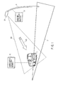
- FIG. 1 is a diagram showing the major components of a position determination system according to an embodiment of the invention.
- the embodiment is a system that determines the present position of an automobile (hereinafter referred to as vehicle) 1, by utilizing a visible-light communication system.
- vehicle an automobile
- the major components of the system are: a lamp post 3 and a position determination apparatus 10.
- the lamp post 3 stands on one side of a road 2 on which the vehicle 1 is running.
- the position determination apparatus 10 (hereinafter called vehicle position determination apparatus) is mounted on the vehicle 1.
- the lamp post 3 has a road-illumination lamp 30 and a visible-light communication apparatus 31.
- the lamp 30 illuminates the road 2.
- the lamp 30 has a light-emitting diode (hereinafter referred to as LED) and emits illumination light 300.
- LED light-emitting diode
- the lamp 30 as a visible-light communication beacon, which will be described later.
- the visible-light communication apparatus 31 drives and controls the LED included in the road-illumination lamp 30, and constitute the visible-light communication beacon.
- the beacon emits a visible optical signal 310 that contains position data.
- the facility composed of the lamp post 3 fixed in position, road-illumination lamp 30 and visible-light communication apparatus 31 will be called "visible-light communication beacon”.
- the vehicle position determination apparatus 10 receives a visible optical signal transmitted from the visible-light communication beacon.
- the visible optical signal is demodulated, providing position data. From the position data, the vehicle position determination apparatus 10 determines the present position of the vehicle 1.
- the position data includes coordinate data (longitude and latitude) and height data.
- the coordinate data represents the position of the visible-light communication beacon that is fixed in position.
- the height data represents the distance from the road 2 to the road-illumination lamp 30. (In other words, the height data represents the height "H" of the visible-light communication beacon.)
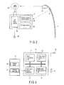
- FIG. 2 is a diagram depicting the configuration of a visible-light communication apparatus 31 according to the embodiment.
- the visible-light communication apparatus 31 is fixed in position to the lamp post 3, and located near the road-illumination lamp 30.
- the apparatus 31 has a power supply 33, an LED drive device 34, a communication control device 35, and a storage device 36.
- the LED drive device 34 drives the LED 32 that is a light-emitting element of the road-illumination lamp 30.
- the communication control device 35 controls the LED drive device 34, ultimately turning on and off the LED 32 repeatedly.
- the LED 32 transmits a visible optical signal 310 modulated with the position data stored in the storage device 36.
- the position data contains the above-mentioned height data and the coordinate data representing the position of the visible-light communication beacon at a fixed position.
- the position data about the visible-light communication beacon has been stored into the storage device 36 beforehand or has been transmitted by radio and then stored into the storage device 36.
- the visible-light communication apparatus 31 modulates the visible light emitted by the LED 32 with the position data, generating a visible optical signal (a visible-light beacon signal) 310.
- the visible light may be modulated an appropriate method selected from the various methods available, such as on-off control and RGB modulation.
- FIG. 3 is a diagram depicting the configuration of a vehicle position determination apparatus 10 according to the embodiment.
- the vehicle 1 has not only the vehicle position determination apparatus 10, but also a car-mount measuring device 16 and a car-mount video camera 19 (hereinafter called camera).
- the car-mount measuring device 16 includes a light-receiving unit 15, a bearing detector 17, and a range finder 18.
- the light-receiving unit 15 receives visible light.
- the light-receiving unit 15 is a photodiode (PD) element, and receives the visible optical signal and converts it to an electric signal which is supplied to the vehicle position determination apparatus 10.
- the bearing detector 17 and the range finder 18 are connected to the vehicle position determination apparatus 10.
- the bearing detector 17 detects the bearing of the vehicle 1 and generates a bearing signal
- the range finder 18 determines the distance the vehicle 1 has traveled and generates a distance signal.
- the bearing signal and the distance signal are output to the vehicle position determination apparatus 10.
- the camera 19 is a single-lens photographing device and generates video data representing any image it has photographed. The video data is output to the vehicle position determination apparatus 10.
- the vehicle position determination apparatus 10 comprises a data processing unit 11, a video data processing unit 12, a visible-light communication unit 13, and a car-mount device interface 14.
- the data processing unit 11 performs operations in order to determine the position of the vehicle 1 as will be described later.
- the video data processing unit 12 processes the video data supplied from the camera 19, generating video data. This video data is transferred to the data processing unit 11 and will be used to calculate the height of the visible-light communication beacon.
- the data processing unit 11 and the video data processing unit 12 are constituted by a microprocessor or software.
- the visible-light communication unit 13 demodulates the visible optical signal (electric signal) received by the light-receiving unit 15, thus restoring the position data.
- the position data thus restored is transferred to the data processing unit 11.
- the car-mount device interface 14 receives the bearing signal and the distance signal from the bearing detector 17 and the range finder 18, respectively, and transfers these signals to the data processing unit 11.
- the position determination system is designed to determine position P2 (second position) the vehicle 1 assumes at present, after travelling on the road from position P1 (first position).
- the road is illuminated with the light emitted from the LED 32 of the road-illumination lamp 30.
- the road-illumination lamp 30 transmits visible optical signals 200 in various directions to the road.
- the signals 200 are visible-light communication beacons, each fixed in a specific position and containing position data.
- the light-receiving unit 15 receives a visible optical signal 200 emitted by the visible-light communication beacon (Step S1).
- the visible-light communication unit 13 receives the visible optical signal 200 from the light-receiving unit 15 and demodulates the signal 200 (electric signal), restoring the position data.
- the position data is transferred to the data processing unit 11.
- the camera 19 photographs the road-illumination lamp 30 and the lamp post 3 holding the lamp 30 at the time the light-receiving unit 15 receives the visible optical signal 200 (Step S1).
- the video data processing unit 12 receives the image 100 photographed by the camera 19.
- the unit 12 processes the image 100, generating video data.
- the video data is transferred to the data processing unit 11 so that the height (H) of the visible-light communication beacon may be calculated.
- the light-receiving unit 15 receives a visible optical signal 200 coming from the visible-light communication beacon.
- the camera 19 photographs the visible-light communication beacon (Step S2). That is, in the vehicle position determination apparatus 10, the visible-light communication unit 13 demodulates the visible optical signal 200, restoring the position data. The position data thus restored is transferred to the data processing unit 11.
- the data processing unit 11 has an internal memory, which holds the position data items restored the moment the vehicle 1 is at the positions P1 and P2, respectively.
- the video data processing unit 12 receives the image 100 photographed by the camera 19, generating video data. The video data is transferred to the data processing unit 11.
- the rangefinder 18 determines the distance Lo the vehicle 1 has traveled from the position P1 to the position P2 and generates a distance signal.
- the distance signal is transferred to the data processing unit 11 of the vehicle position determination apparatus 10.
- the data representing the distance Lo is stored in the internal memory.
- the data processing unit 11 synthesizes two video data items the video data processing unit 12 has acquired at the positions P1 and P2, respectively, generating synthesized video data. Using the synthesized video data, the position data and the data representing the distance Lo (distance the vehicle 1 has traveled), the data processing unit 11 determines the distance Lx between the position (P2) of the vehicle 1 and the visible-light communication beacon and also the coordinates of the position P2 (Step S3).
- the data processing unit 11 further receives data representing the bearing angle detected by the bearing detector 17 at the position P2, from the car-mount measuring device 16 through the car-mount device interface 14. Based on the bearing angle, the data processing unit 11 corrects the coordinates of the position P2, thereby calculating the present position of the vehicle 1 (Step S4).
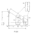
- a sequence of calculation the vehicle position determination apparatus 10 according to this embodiment performs to determine the position of the vehicle 1 will be explained in detail, with reference to FIGS. 5 and 6 .
- the apparatus 10 calculates the distance Lx between the position P2 and the visible-light communication beacon, on the assumption that the vehicle 1 has travelled from the position P1 on the road to the position P2.
- the position 700 of the visible-light communication beacon is defined, for the sake of convenience, as distance between the road-illumination lamp 30 and the intersection of the road surface and a perpendicular extending from the lamp 30.
- the data processing unit 11 calculates the height h of the lamp post 3, as measured in a synthesized image 600 obtained by synthesizing two video data items 400 and 500 garnered at the positions P1 and P2 by the video data processing unit 12.
- the height h is the difference between the height ha that the camera 19 has at the position P1 and a point hb at which the position P2 intersects with a line along which the road-illumination lamp 30 is photographed at angle ⁇ .
- H the height of the visible-light communication beacon 700
- vh the height of the camera 19 mounted on the vehicle 1
- L is the distance between the position P1 and the position 700 of the visible-light communication beacon.
- the data processing unit 11 calculates the distance Lo between the positions P1 and P2 from the travel distance of the vehicle 1, determined by the rangefinder 18.
- the data processing unit 11 finds the height H of the visible-light communication beacon, from the position data acquired by demodulating the visible optical signal 200 the light-receiving unit 15 has received.
- the data processing unit 11 of the vehicle position determination apparatus 10 performs calculations based on the relations (1) to (5) specified above, finding the distance Lx between the vehicle 1 traveled to the position P2 and the position 700 of the visible-light communication beacon.
- the position of the visible-light communication beacon is defined by coordinates (xo, yo).
- the coordinates are position data that generally represents the longitude and the latitude.
- the light-receiving unit 15 receives visible optical signal 200, and the visible-light communication unit 13 demodulates the signal 200, extracting the coordinates (xo, yo).
- the position data representing the coordinates (xo, yo) is transferred to the data processing unit 11. Meanwhile, the data processing unit 11 obtains the bearing angle ⁇ from the bearing detector 17 of the car-mount measuring device 16 through the car-mount device interface 14.
- the data processing unit 11 corrects the coordinates (xo, yo) of the visible-light communication beacon by using the relations (6) and (7) given below, calculating the coordinates (x, y) of the position P2 where the vehicle 1 momentarily stays. More precisely, the data processing unit 11 correcting the coordinates (xo, yo) of the beacon calculates the coordinates (x, y) by using the distance Lx between the vehicle 1 and the position of the beacon, calculating the coordinates (x, y) of the position P2, i.e., the present position of the vehicle 1.
- the data processing unit 11 can find the coordinates (x, y) of the vehicle 1 from the coordinates (xo, yo) of the visible-light communication beacon, the distance Lx between the vehicle 1 and the position of the beacon, and the bearing angle ⁇ of the vehicle 1.
- the distance Lx between the vehicle 1 and the visible-light communication beacon can be obtained by means of so-called trigonometrical survey, using a synthesized image prepared by synthesizing images photographed by one camera 19.
- the distance Lx between the vehicle 1 and the beacon can be calculated in the system according to the embodiment, merely using a single-lens camera 19, without using a plurality of cameras or a complex video data process such as stereoscopic-image processing.
- the distance Lx can be calculated at lower cost than in the case where a plurality of cameras is used.
- the system according to the embodiment can easily be put to practical use, because most automobiles recently manufactured and sold have one camera each.
- the system according to the embodiment can find the coordinates of the vehicle 1 with high accuracy, because the coordinates (xo, yo) of the beacon is corrected.
- the embodiment can provide a position determination system that utilizes a visible-light communication system and can yet be easily to use at low cost.
- the visible-light communication beacon is constituted by the road-illumination lamp 30 located at a fixed position. Nonetheless, the visible-light communication beacon may be constituted by, for example, an illumination lamp of such a type that finds use in buildings or facilities. Further, the visible-light communication beacon need not be integrated with the illumination lamp. It may an independent device that transmits visible optical signals.
Landscapes
- Physics & Mathematics (AREA)
- General Physics & Mathematics (AREA)
- Engineering & Computer Science (AREA)
- Radar, Positioning & Navigation (AREA)
- Remote Sensing (AREA)
- Atmospheric Sciences (AREA)
- Electromagnetism (AREA)
- Life Sciences & Earth Sciences (AREA)
- Computer Networks & Wireless Communication (AREA)
- Traffic Control Systems (AREA)
- Navigation (AREA)
- Optical Communication System (AREA)
- Length Measuring Devices By Optical Means (AREA)
- Measurement Of Optical Distance (AREA)
Applications Claiming Priority (1)
| Application Number | Priority Date | Filing Date | Title |
|---|---|---|---|
| JP2007199543A JP2009036571A (ja) | 2007-07-31 | 2007-07-31 | 可視光通信システムを利用した位置測定システム、位置測定装置及び位置測定方法 |
Publications (2)
| Publication Number | Publication Date |
|---|---|
| EP2026086A2 true EP2026086A2 (de) | 2009-02-18 |
| EP2026086A3 EP2026086A3 (de) | 2009-08-12 |
Family
ID=39870503
Family Applications (1)
| Application Number | Title | Priority Date | Filing Date |
|---|---|---|---|
| EP08158636A Withdrawn EP2026086A3 (de) | 2007-07-31 | 2008-06-19 | Vorrichtung und Verfahren zur Bestimmung der Position eines beweglichen Objekts mittels sichtbarer Lichtkommunikation |
Country Status (7)
| Country | Link |
|---|---|
| US (1) | US7973819B2 (de) |
| EP (1) | EP2026086A3 (de) |
| JP (1) | JP2009036571A (de) |
| KR (1) | KR101014758B1 (de) |
| CN (1) | CN101358846B (de) |
| RU (1) | RU2406232C2 (de) |
| TW (1) | TWI366802B (de) |
Cited By (4)
| Publication number | Priority date | Publication date | Assignee | Title |
|---|---|---|---|---|
| CN104539738A (zh) * | 2015-01-22 | 2015-04-22 | 重庆邮电大学 | 一种led通信的车辆自组织网络 |
| CN105301562A (zh) * | 2015-10-21 | 2016-02-03 | 宁波大学 | 可见光通信无线定位系统 |
| WO2017096360A1 (en) * | 2015-12-03 | 2017-06-08 | Osram Sylvania Inc. | Light-based vehicle positioning for mobile transport systems |
| US11107339B2 (en) | 2016-11-11 | 2021-08-31 | Carrier Corporation | High sensitivity fiber optic based detection |
Families Citing this family (97)
| Publication number | Priority date | Publication date | Assignee | Title |
|---|---|---|---|---|
| JP2008249666A (ja) * | 2007-03-30 | 2008-10-16 | Fujitsu Ten Ltd | 車両位置特定装置および車両位置特定方法 |
| JP4839330B2 (ja) * | 2008-02-29 | 2011-12-21 | 東芝テリー株式会社 | 画像処理装置および画像処理プログラム |
| JP5548888B2 (ja) * | 2009-04-24 | 2014-07-16 | 真一郎 春山 | レーザ通信機 |
| JP5365792B2 (ja) * | 2009-06-01 | 2013-12-11 | マツダ株式会社 | 車両用位置測定装置 |
| JP5397030B2 (ja) * | 2009-06-15 | 2014-01-22 | カシオ計算機株式会社 | 動画記録装置及びプログラム |
| TWI437509B (zh) * | 2009-08-18 | 2014-05-11 | Ind Tech Res Inst | 光資訊接收方法 |
| JP2011055288A (ja) * | 2009-09-02 | 2011-03-17 | Toshiba Corp | 可視光通信装置及びデータ受信方法 |
| KR101064665B1 (ko) | 2009-12-28 | 2011-09-15 | 전자부품연구원 | 차량용 가시광 통신장치, 가시광 통신을 이용한 터널 내 차량통신시스템 및 방법 |
| US10210763B2 (en) | 2010-12-22 | 2019-02-19 | Philips Lighting Holdingb.V. | Vehicle positioning and guidance system |
| US8862395B2 (en) * | 2011-01-31 | 2014-10-14 | Raytheon Company | Coded marker navigation system and method |
| US9787397B2 (en) | 2011-07-26 | 2017-10-10 | Abl Ip Holding Llc | Self identifying modulated light source |
| US8436896B2 (en) | 2011-07-26 | 2013-05-07 | ByteLight, Inc. | Method and system for demodulating a digital pulse recognition signal in a light based positioning system using a Fourier transform |
| US8520065B2 (en) | 2011-07-26 | 2013-08-27 | ByteLight, Inc. | Method and system for video processing to determine digital pulse recognition tones |
| US8457502B2 (en) | 2011-07-26 | 2013-06-04 | ByteLight, Inc. | Method and system for modulating a beacon light source in a light based positioning system |
| US9444547B2 (en) | 2011-07-26 | 2016-09-13 | Abl Ip Holding Llc | Self-identifying one-way authentication method using optical signals |
| US8334898B1 (en) | 2011-07-26 | 2012-12-18 | ByteLight, Inc. | Method and system for configuring an imaging device for the reception of digital pulse recognition information |
| US8248467B1 (en) | 2011-07-26 | 2012-08-21 | ByteLight, Inc. | Light positioning system using digital pulse recognition |
| US9418115B2 (en) | 2011-07-26 | 2016-08-16 | Abl Ip Holding Llc | Location-based mobile services and applications |
| US8416290B2 (en) | 2011-07-26 | 2013-04-09 | ByteLight, Inc. | Method and system for digital pulse recognition demodulation |
| US8994799B2 (en) | 2011-07-26 | 2015-03-31 | ByteLight, Inc. | Method and system for determining the position of a device in a light based positioning system using locally stored maps |
| US9287976B2 (en) | 2011-07-26 | 2016-03-15 | Abl Ip Holding Llc | Independent beacon based light position system |
| US8334901B1 (en) | 2011-07-26 | 2012-12-18 | ByteLight, Inc. | Method and system for modulating a light source in a light based positioning system using a DC bias |
| US8432438B2 (en) | 2011-07-26 | 2013-04-30 | ByteLight, Inc. | Device for dimming a beacon light source used in a light based positioning system |
| US9723676B2 (en) | 2011-07-26 | 2017-08-01 | Abl Ip Holding Llc | Method and system for modifying a beacon light source for use in a light based positioning system |
| CN102956114B (zh) * | 2011-08-31 | 2015-05-27 | 深圳光启高等理工研究院 | 基于可见光无线通信的交通服务系统 |
| GB2496379A (en) | 2011-11-04 | 2013-05-15 | Univ Edinburgh | A freespace optical communication system which exploits the rolling shutter mechanism of a CMOS camera |
| CN103292819B (zh) * | 2012-02-29 | 2015-10-07 | 深圳光启智能光子技术有限公司 | 基于可见光通信的车辆导航系统 |
| US9576484B2 (en) * | 2012-03-02 | 2017-02-21 | Laser Technology, Inc. | System and method for monitoring vehicular traffic with a laser rangefinding and speed measurement device utilizing a shaped divergent laser beam pattern |
| CN102610115A (zh) * | 2012-03-09 | 2012-07-25 | 郭丰亮 | 基于led可见光通信的智能交通系统 |
| KR101324364B1 (ko) | 2012-03-16 | 2013-11-01 | 광운대학교 산학협력단 | 광원과 센서를 이용한 측위 시스템 및 방법 |
| CN103363995A (zh) * | 2012-04-01 | 2013-10-23 | 深圳光启创新技术有限公司 | 基于可见光通信的地图导航发送装置 |
| CN103363996B (zh) * | 2012-04-01 | 2017-09-19 | 深圳光启智能光子技术有限公司 | 基于可见光通信的地图导航接收装置 |
| CN103363984B (zh) * | 2012-04-01 | 2017-09-19 | 深圳光启智能光子技术有限公司 | 基于可见光通信的地图导航系统 |
| CN103386993B (zh) * | 2012-05-09 | 2015-11-18 | 深圳市坐标系交通技术有限公司 | 采集列车运行信息的系统、光发射装置和光接收处理装置 |
| US8752761B2 (en) * | 2012-09-21 | 2014-06-17 | Symbol Technologies, Inc. | Locationing using mobile device, camera, and a light source |
| TWI573481B (zh) * | 2012-12-17 | 2017-03-01 | 鴻海精密工業股份有限公司 | 手機定位系統 |
| US8988574B2 (en) | 2012-12-27 | 2015-03-24 | Panasonic Intellectual Property Corporation Of America | Information communication method for obtaining information using bright line image |
| US8922666B2 (en) | 2012-12-27 | 2014-12-30 | Panasonic Intellectual Property Corporation Of America | Information communication method |
| US10303945B2 (en) | 2012-12-27 | 2019-05-28 | Panasonic Intellectual Property Corporation Of America | Display method and display apparatus |
| US9247180B2 (en) | 2012-12-27 | 2016-01-26 | Panasonic Intellectual Property Corporation Of America | Video display method using visible light communication image including stripe patterns having different pitches |
| SG11201504978WA (en) * | 2012-12-27 | 2015-07-30 | Panasonic Ip Corp America | Information communication method |
| CN104871454B (zh) | 2012-12-27 | 2018-09-28 | 松下电器(美国)知识产权公司 | 信息通信方法和信息通信装置 |
| US9608725B2 (en) | 2012-12-27 | 2017-03-28 | Panasonic Intellectual Property Corporation Of America | Information processing program, reception program, and information processing apparatus |
| US9088360B2 (en) | 2012-12-27 | 2015-07-21 | Panasonic Intellectual Property Corporation Of America | Information communication method |
| US9560284B2 (en) | 2012-12-27 | 2017-01-31 | Panasonic Intellectual Property Corporation Of America | Information communication method for obtaining information specified by striped pattern of bright lines |
| US10530486B2 (en) | 2012-12-27 | 2020-01-07 | Panasonic Intellectual Property Corporation Of America | Transmitting method, transmitting apparatus, and program |
| EP2940893B1 (de) | 2012-12-27 | 2021-05-19 | Panasonic Intellectual Property Corporation of America | Informationsübermittlungsverfahren |
| WO2014103151A1 (ja) * | 2012-12-27 | 2014-07-03 | パナソニック株式会社 | 情報通信方法 |
| CN104871452B (zh) | 2012-12-27 | 2018-04-27 | 松下电器(美国)知识产权公司 | 可视光通信方法及可视光通信装置 |
| US9087349B2 (en) | 2012-12-27 | 2015-07-21 | Panasonic Intellectual Property Corporation Of America | Information communication method |
| US9608727B2 (en) | 2012-12-27 | 2017-03-28 | Panasonic Intellectual Property Corporation Of America | Switched pixel visible light transmitting method, apparatus and program |
| US10951310B2 (en) | 2012-12-27 | 2021-03-16 | Panasonic Intellectual Property Corporation Of America | Communication method, communication device, and transmitter |
| US10523876B2 (en) | 2012-12-27 | 2019-12-31 | Panasonic Intellectual Property Corporation Of America | Information communication method |
| CN103116994B (zh) * | 2012-12-28 | 2015-01-07 | 方科峰 | 光通讯的交通系统及交通系统管理方法 |
| US9705600B1 (en) | 2013-06-05 | 2017-07-11 | Abl Ip Holding Llc | Method and system for optical communication |
| RU2533348C1 (ru) * | 2013-07-04 | 2014-11-20 | Святослав Николаевич Гузевич | Оптический способ измерения размеров и положения объекта и дальномер-пеленгатор |
| TWI552909B (zh) * | 2013-07-30 | 2016-10-11 | Vehicle visible light communication system | |
| EP3045016B1 (de) | 2013-09-10 | 2018-04-11 | Philips Lighting Holding B.V. | Verfahren und vorrichtung für automatisierte inbetriebnahme von codierten lichtquellen |
| EP3044549A2 (de) * | 2013-09-13 | 2016-07-20 | Philips Lighting Holding B.V. | System und verfahren zur unterstützung von erweiterter realität |
| CN104467962B (zh) | 2013-09-18 | 2018-08-14 | 华为技术有限公司 | 一种基于可视光源的定位方法、移动终端及控制器 |
| US9201145B2 (en) * | 2013-10-17 | 2015-12-01 | Globalfoundries Inc. | Object location in three dimensional space using LED lights |
| WO2015077767A1 (en) | 2013-11-25 | 2015-05-28 | Daniel Ryan | System and method for communication with a mobile device via a positioning system including rf communication devices and modulated beacon light sources |
| CN103869284A (zh) * | 2014-02-28 | 2014-06-18 | 北京邮电大学 | 基于可见光通信的室内定位系统以及方法 |
| US9948391B2 (en) * | 2014-03-25 | 2018-04-17 | Osram Sylvania Inc. | Techniques for determining a light-based communication receiver position |
| EP3123194B1 (de) * | 2014-03-25 | 2024-08-14 | Osram Sylvania Inc. | Navigation über lichtbasierte kommunikation |
| CN103869285B (zh) * | 2014-04-01 | 2016-04-06 | 中国人民解放军信息工程大学 | 一种利用可见光进行定位的方法和装置 |
| CN104038285A (zh) * | 2014-06-16 | 2014-09-10 | 上海航天电子通讯设备研究所 | 基于tcp/ip的室内可见光通信节点及双向通信系统 |
| CN105444752A (zh) * | 2014-09-02 | 2016-03-30 | 深圳市芯通信息科技有限公司 | 基于光源亮度的室内定位方法、装置及系统 |
| US9791544B2 (en) | 2016-02-01 | 2017-10-17 | Qualcomm Incorporated | Location determination using light-based communications |
| JP6707378B2 (ja) * | 2016-03-25 | 2020-06-10 | 本田技研工業株式会社 | 自己位置推定装置および自己位置推定方法 |
| DE102016208488A1 (de) * | 2016-05-18 | 2017-11-23 | Robert Bosch Gmbh | Verfahren und Vorrichtung zur Lokalisierung eines Fahrzeugs |
| RU2638876C1 (ru) * | 2016-06-15 | 2017-12-18 | Михаил Николаевич Матвеев | Универсальный способ управления движением объекта с помощью оптической навигационной системы |
| RU2649840C1 (ru) * | 2016-12-28 | 2018-04-04 | Михаил Дмитриевич Косткин | Способ управления движением транспортного средства (варианты) |
| JP6615811B2 (ja) * | 2017-03-17 | 2019-12-04 | 株式会社東芝 | 移動体位置推定システム、装置及び方法 |
| CN107168306A (zh) * | 2017-04-05 | 2017-09-15 | 罗厚兵 | 道路信标 |
| EP3421936A1 (de) | 2017-06-30 | 2019-01-02 | Panasonic Automotive & Industrial Systems Europe GmbH | Optisches markierungselement für geostandortinformationen |
| CN107504960B (zh) * | 2017-07-28 | 2019-10-01 | 西安电子科技大学 | 车辆定位方法和系统 |
| CN107734449B (zh) * | 2017-11-09 | 2020-05-12 | 陕西外号信息技术有限公司 | 一种基于光标签的室外辅助定位方法、系统及设备 |
| JP6701153B2 (ja) * | 2017-11-10 | 2020-05-27 | 株式会社Subaru | 移動体の位置計測システム |
| KR101971370B1 (ko) * | 2017-12-18 | 2019-08-13 | 국민대학교산학협력단 | 광학 카메라 통신을 이용하는 차량 위치 추정 방법 및 장치 |
| EP3738316B1 (de) | 2018-01-12 | 2025-09-24 | Intelligent Security Systems Corporation | Systeme und verfahren zur bildbasierten lichtausgabe |
| KR101990734B1 (ko) * | 2018-01-12 | 2019-06-19 | 숭실대학교산학협력단 | 복수의 카메라들로부터의 이미지들을 융합하여 차량의 위치를 추정하는 시스템 |
| KR101996169B1 (ko) * | 2018-01-12 | 2019-07-03 | 숭실대학교산학협력단 | 카메라 변위를 고려한 가시광 통신 기반의 차량 위치 추정 방법 및 장치 |
| KR101996168B1 (ko) * | 2018-01-12 | 2019-07-03 | 숭실대학교산학협력단 | Cmos 센서의 롤링 셔터 보정을 고려한 가시광 통신 기반의 차량 위치 추정 방법 및 장치 |
| CN108528326B (zh) * | 2018-04-04 | 2020-06-23 | 王小红 | 一种车载互联互通方法 |
| CN108363052A (zh) * | 2018-05-22 | 2018-08-03 | 广东工业大学 | 一种基于可见光通信的室内定位系统及方法 |
| CN108692701B (zh) * | 2018-05-28 | 2020-08-07 | 佛山市南海区广工大数控装备协同创新研究院 | 基于粒子滤波器的移动机器人多传感器融合定位方法 |
| CN108597228B (zh) * | 2018-05-30 | 2023-08-29 | 中国科学技术大学 | 基于可见光感知的交通流智能感知系统及方法 |
| US11280875B2 (en) | 2018-06-29 | 2022-03-22 | Stefanie Cincotta | Visible light positioning receiver arrangement and two stage positioning method |
| CN109596067B (zh) * | 2018-12-25 | 2020-08-25 | 东南大学 | 一种钢厂行车调度用三维激光扫描可见光确认方法 |
| RU2744510C2 (ru) * | 2019-01-09 | 2021-03-11 | Общество с ограниченной ответственностью "ИСС-СОФТ" | Система и способ формирования светового потока на основании изображений |
| CN110133685B (zh) * | 2019-05-22 | 2023-04-14 | 吉林大学 | 基于occ的路灯辅助手机详细定位通信系统 |
| CN112213689A (zh) * | 2019-07-09 | 2021-01-12 | 阿里巴巴集团控股有限公司 | 导航方法以及定位方法、装置、设备 |
| US12481060B2 (en) | 2020-04-29 | 2025-11-25 | Lg Electronics Inc. | Method for operating RSU related to VRU location in wireless communication system |
| US12119873B2 (en) | 2020-12-17 | 2024-10-15 | Toyota Motor Engineering & Manufacturing North America, Inc. | System and method for determining actions of a vehicle by visible light communication |
| EP4538589A1 (de) | 2022-06-10 | 2025-04-16 | Furukawa Electric Co., Ltd. | Verbundstruktur für beleuchtungsvorrichtung und drahtloses kommunikationsgerät |
| KR102612593B1 (ko) * | 2022-09-14 | 2023-12-08 | 인천대학교 산학협력단 | 전방 차량의 위치에 따라 지향성 광신호를 전송할 수 있는 차량용 신호 전송 장치 및 그 동작 방법 |
Citations (1)
| Publication number | Priority date | Publication date | Assignee | Title |
|---|---|---|---|---|
| JP2007081703A (ja) | 2005-09-13 | 2007-03-29 | Toshiba Corp | 可視光通信システム及びその方法 |
Family Cites Families (21)
| Publication number | Priority date | Publication date | Assignee | Title |
|---|---|---|---|---|
| SU1310871A1 (ru) * | 1985-04-01 | 1987-05-15 | Предприятие П/Я В-8150 | Устройство определени местоположени подвижного транспортного средства |
| RU2092902C1 (ru) * | 1993-12-27 | 1997-10-10 | Российский научно-исследовательский институт космического приборостроения | Способ определения местоположения транспортного средства и устройство, реализующее этот способ |
| EP0678731B1 (de) * | 1994-04-15 | 1999-06-30 | Nissan Motor Co., Ltd. | Fahrzeug-Navigationssystem |
| JP3835628B2 (ja) * | 1996-09-05 | 2006-10-18 | マツダ株式会社 | ナビゲーション装置 |
| JP4121642B2 (ja) * | 1998-11-13 | 2008-07-23 | 株式会社トプコン | 建設機械制御システム |
| JP2002202741A (ja) | 2000-11-02 | 2002-07-19 | Matsushita Electric Ind Co Ltd | Ledによる情報提供装置 |
| US6865347B2 (en) * | 2001-01-05 | 2005-03-08 | Motorola, Inc. | Optically-based location system and method for determining a location at a structure |
| DE10101992C2 (de) * | 2001-01-18 | 2002-12-05 | Eads Deutschland Gmbh | Radarverfahren zur Erkennung und Endeckung verdeckter Ziele |
| US20070059098A1 (en) * | 2002-03-25 | 2007-03-15 | Ian Mayfield | Automatic ground marking method and apparatus |
| KR100435654B1 (ko) * | 2001-06-20 | 2004-06-12 | 현대자동차주식회사 | 자동차의 차선 이탈 방지를 위한 제어 방법 |
| JP4338387B2 (ja) | 2002-12-10 | 2009-10-07 | 日本ビクター株式会社 | 可視光受信装置及び可視光通信装置 |
| ATE372894T1 (de) * | 2002-12-20 | 2007-09-15 | Murakami Corp | Aussenspiegel |
| US7010401B1 (en) * | 2003-06-26 | 2006-03-07 | The United States Of America As Represented By The Secretary Of The Navy | System for guiding a vehicle to a position |
| JP4398430B2 (ja) * | 2003-10-31 | 2010-01-13 | 富士通株式会社 | 距離算出装置および算出プログラム |
| US7123186B2 (en) * | 2004-03-26 | 2006-10-17 | Topcon Gps, Llc | Controlling solution latency in a global navigation satellite receiver |
| US7706917B1 (en) * | 2004-07-07 | 2010-04-27 | Irobot Corporation | Celestial navigation system for an autonomous robot |
| JP4052310B2 (ja) * | 2005-02-07 | 2008-02-27 | 住友電気工業株式会社 | 交差点までの距離算出方法、装置及びシステム |
| JP2006220465A (ja) * | 2005-02-09 | 2006-08-24 | Nippon Signal Co Ltd:The | 位置特定システム |
| US7728869B2 (en) * | 2005-06-14 | 2010-06-01 | Lg Electronics Inc. | Matching camera-photographed image with map data in portable terminal and travel route guidance method |
| JP4478885B2 (ja) * | 2005-06-28 | 2010-06-09 | ソニー株式会社 | 情報処理装置および方法、プログラム、並びに記録媒体 |
| DE102005061786B4 (de) * | 2005-12-23 | 2007-10-31 | Lübeck, Felix | Lichtsignalanlage mit Übertragung zusätzlicher Informationen |
-
2007
- 2007-07-31 JP JP2007199543A patent/JP2009036571A/ja active Pending
-
2008
- 2008-06-19 EP EP08158636A patent/EP2026086A3/de not_active Withdrawn
- 2008-06-24 TW TW097123570A patent/TWI366802B/zh not_active IP Right Cessation
- 2008-06-30 KR KR1020080062294A patent/KR101014758B1/ko not_active Expired - Fee Related
- 2008-06-30 CN CN2008101446457A patent/CN101358846B/zh not_active Expired - Fee Related
- 2008-07-17 US US12/174,815 patent/US7973819B2/en not_active Expired - Fee Related
- 2008-07-30 RU RU2008131545/09A patent/RU2406232C2/ru not_active IP Right Cessation
Patent Citations (1)
| Publication number | Priority date | Publication date | Assignee | Title |
|---|---|---|---|---|
| JP2007081703A (ja) | 2005-09-13 | 2007-03-29 | Toshiba Corp | 可視光通信システム及びその方法 |
Cited By (8)
| Publication number | Priority date | Publication date | Assignee | Title |
|---|---|---|---|---|
| CN104539738A (zh) * | 2015-01-22 | 2015-04-22 | 重庆邮电大学 | 一种led通信的车辆自组织网络 |
| CN104539738B (zh) * | 2015-01-22 | 2018-04-27 | 重庆邮电大学 | 一种led通信的车辆自组织网络 |
| CN105301562A (zh) * | 2015-10-21 | 2016-02-03 | 宁波大学 | 可见光通信无线定位系统 |
| CN105301562B (zh) * | 2015-10-21 | 2017-06-23 | 宁波大学 | 可见光通信无线定位系统 |
| WO2017096360A1 (en) * | 2015-12-03 | 2017-06-08 | Osram Sylvania Inc. | Light-based vehicle positioning for mobile transport systems |
| CN108604382A (zh) * | 2015-12-03 | 2018-09-28 | 奥斯兰姆施尔凡尼亚公司 | 用于移动运输系统的基于光的车辆定位 |
| US10891754B2 (en) | 2015-12-03 | 2021-01-12 | Osram Sylvania Inc. | Light-based vehicle positioning for mobile transport systems |
| US11107339B2 (en) | 2016-11-11 | 2021-08-31 | Carrier Corporation | High sensitivity fiber optic based detection |
Also Published As
| Publication number | Publication date |
|---|---|
| US7973819B2 (en) | 2011-07-05 |
| EP2026086A3 (de) | 2009-08-12 |
| CN101358846B (zh) | 2011-01-26 |
| RU2008131545A (ru) | 2010-02-10 |
| KR20090013026A (ko) | 2009-02-04 |
| US20090033757A1 (en) | 2009-02-05 |
| CN101358846A (zh) | 2009-02-04 |
| KR101014758B1 (ko) | 2011-02-15 |
| RU2406232C2 (ru) | 2010-12-10 |
| TW200923855A (en) | 2009-06-01 |
| TWI366802B (en) | 2012-06-21 |
| JP2009036571A (ja) | 2009-02-19 |
Similar Documents
| Publication | Publication Date | Title |
|---|---|---|
| EP2026086A2 (de) | Vorrichtung und Verfahren zur Bestimmung der Position eines beweglichen Objekts mittels sichtbarer Lichtkommunikation | |
| US12125234B2 (en) | Automated license plate recognition system and related method | |
| JP4600357B2 (ja) | 測位装置 | |
| US6470265B1 (en) | Method and apparatus for processing digital map data | |
| Cui et al. | Real-time global localization of robotic cars in lane level via lane marking detection and shape registration | |
| US20110050903A1 (en) | Method for determining position and orientation of vehicle trailers | |
| KR20180101717A (ko) | 맵들을 사용하는 차량 컴포넌트 제어 | |
| JP2008268204A (ja) | 明滅する光学的ビーコンを使用した、車両のための目標ナビゲーション | |
| FR2557971B1 (fr) | Systeme de surveillance par avion sans pilote permettant la localisation d'objectif | |
| JP2008215991A (ja) | 測位装置及び測位システム | |
| JP2018109815A (ja) | 走行支援装置、走行支援方法およびコンピュータを走行支援装置として機能させるためのプログラム | |
| JP2010002225A (ja) | 可視光通信を利用した位置測定装置、位置測定システム、及び位置測定方法 | |
| JP2007206099A (ja) | 地図作成支援システム | |
| JP7265269B2 (ja) | マップデータの修正方法及び修正プログラム | |
| JP2001142532A (ja) | 移動体の位置検出装置 | |
| JP6707378B2 (ja) | 自己位置推定装置および自己位置推定方法 | |
| EP4113063A1 (de) | Lokalisierung von autonomen fahrzeugen mittels kamera, gps und imu | |
| CN102288180B (zh) | 实时影像导航系统及方法 | |
| KR101017997B1 (ko) | 교통 정보 제공 시스템 | |
| JP2007240380A (ja) | トンネル内位置検出装置 | |
| US10830906B2 (en) | Method of adaptive weighting adjustment positioning | |
| JP2017181393A (ja) | ナビゲーション装置及びナビゲーション方法 | |
| US20050060090A1 (en) | Vehicle-type measurement system | |
| KR20230120211A (ko) | 자율 주행 차량의 자기 위치 인식 장치 | |
| JP2021169989A (ja) | 自己位置測定システム、車両、及び、自己位置測定方法 |
Legal Events
| Date | Code | Title | Description |
|---|---|---|---|
| PUAI | Public reference made under article 153(3) epc to a published international application that has entered the european phase |
Free format text: ORIGINAL CODE: 0009012 |
|
| 17P | Request for examination filed |
Effective date: 20080619 |
|
| AK | Designated contracting states |
Kind code of ref document: A2 Designated state(s): AT BE BG CH CY CZ DE DK EE ES FI FR GB GR HR HU IE IS IT LI LT LU LV MC MT NL NO PL PT RO SE SI SK TR |
|
| AX | Request for extension of the european patent |
Extension state: AL BA MK RS |
|
| PUAL | Search report despatched |
Free format text: ORIGINAL CODE: 0009013 |
|
| AK | Designated contracting states |
Kind code of ref document: A3 Designated state(s): AT BE BG CH CY CZ DE DK EE ES FI FR GB GR HR HU IE IS IT LI LT LU LV MC MT NL NO PL PT RO SE SI SK TR |
|
| AX | Request for extension of the european patent |
Extension state: AL BA MK RS |
|
| 17Q | First examination report despatched |
Effective date: 20090921 |
|
| AKX | Designation fees paid |
Designated state(s): DE FR |
|
| STAA | Information on the status of an ep patent application or granted ep patent |
Free format text: STATUS: THE APPLICATION IS DEEMED TO BE WITHDRAWN |
|
| 18D | Application deemed to be withdrawn |
Effective date: 20160223 |