EP2026089A2 - Dispositif et procédé destinés à la détermination de la position d'un appareil hertzien mobile - Google Patents
Dispositif et procédé destinés à la détermination de la position d'un appareil hertzien mobile Download PDFInfo
- Publication number
- EP2026089A2 EP2026089A2 EP08014244A EP08014244A EP2026089A2 EP 2026089 A2 EP2026089 A2 EP 2026089A2 EP 08014244 A EP08014244 A EP 08014244A EP 08014244 A EP08014244 A EP 08014244A EP 2026089 A2 EP2026089 A2 EP 2026089A2
- Authority
- EP
- European Patent Office
- Prior art keywords
- base station
- determining
- mobile
- cell
- station transceiver
- Prior art date
- Legal status (The legal status is an assumption and is not a legal conclusion. Google has not performed a legal analysis and makes no representation as to the accuracy of the status listed.)
- Withdrawn
Links
- 238000000034 method Methods 0.000 title claims abstract description 26
- 238000005259 measurement Methods 0.000 claims abstract description 54
- 238000004590 computer program Methods 0.000 claims abstract description 6
- 230000005540 biological transmission Effects 0.000 claims description 3
- 210000004027 cell Anatomy 0.000 description 107
- 230000005484 gravity Effects 0.000 description 13
- 238000002592 echocardiography Methods 0.000 description 6
- 238000012935 Averaging Methods 0.000 description 5
- 230000004807 localization Effects 0.000 description 4
- 238000012360 testing method Methods 0.000 description 4
- 101150080339 BTS1 gene Proteins 0.000 description 3
- 238000007796 conventional method Methods 0.000 description 3
- 238000013459 approach Methods 0.000 description 2
- 238000005315 distribution function Methods 0.000 description 2
- 238000005516 engineering process Methods 0.000 description 2
- 238000011156 evaluation Methods 0.000 description 2
- 241000220317 Rosa Species 0.000 description 1
- 230000001413 cellular effect Effects 0.000 description 1
- 238000010586 diagram Methods 0.000 description 1
- 230000009429 distress Effects 0.000 description 1
- 238000010295 mobile communication Methods 0.000 description 1
- 230000000644 propagated effect Effects 0.000 description 1
- 238000013139 quantization Methods 0.000 description 1
Images







Classifications
-
- G—PHYSICS
- G01—MEASURING; TESTING
- G01S—RADIO DIRECTION-FINDING; RADIO NAVIGATION; DETERMINING DISTANCE OR VELOCITY BY USE OF RADIO WAVES; LOCATING OR PRESENCE-DETECTING BY USE OF THE REFLECTION OR RERADIATION OF RADIO WAVES; ANALOGOUS ARRANGEMENTS USING OTHER WAVES
- G01S5/00—Position-fixing by co-ordinating two or more direction or position line determinations; Position-fixing by co-ordinating two or more distance determinations
- G01S5/02—Position-fixing by co-ordinating two or more direction or position line determinations; Position-fixing by co-ordinating two or more distance determinations using radio waves
- G01S5/0252—Radio frequency fingerprinting
-
- G—PHYSICS
- G01—MEASURING; TESTING
- G01S—RADIO DIRECTION-FINDING; RADIO NAVIGATION; DETERMINING DISTANCE OR VELOCITY BY USE OF RADIO WAVES; LOCATING OR PRESENCE-DETECTING BY USE OF THE REFLECTION OR RERADIATION OF RADIO WAVES; ANALOGOUS ARRANGEMENTS USING OTHER WAVES
- G01S5/00—Position-fixing by co-ordinating two or more direction or position line determinations; Position-fixing by co-ordinating two or more distance determinations
- G01S5/02—Position-fixing by co-ordinating two or more direction or position line determinations; Position-fixing by co-ordinating two or more distance determinations using radio waves
- G01S5/14—Determining absolute distances from a plurality of spaced points of known location
-
- H—ELECTRICITY
- H04—ELECTRIC COMMUNICATION TECHNIQUE
- H04W—WIRELESS COMMUNICATION NETWORKS
- H04W64/00—Locating users or terminals or network equipment for network management purposes, e.g. mobility management
Definitions
- the present invention relates to the location of mobile phones in mobile networks.
- the localization of mobile phones especially if they do not have a built-in GPS (Global Positioning System) GPS receiver or no GPS coverage is available, in the conventional technique by evaluating the information obtained by the connection of the Mobile phones can be obtained with the mobile network and its network infrastructure.
- the localization can be performed by evaluating a position of a transmitting mast of a radio cell, in which a mobile phone is registered.
- Some radio cells are characterized by sectorized antennas, in which case a virtual center of a sector may be indicated as the location of the mobile telephone in which the mobile telephone is registered.
- This approach allows a position determination of a mobile phone, or a mobile station, only with limited accuracy. This is particularly disadvantageous in situations in which emergencies occur and a timely arrival of emergency services is essential.
- GSM Global System for Mobile Communication
- TDD Time Division Duplex, Time Division Duplex, UMTS
- accurate measurement of a propagation time of the radio signals between a base station transceiver and a mobile station is provided, such as may occur in FDD UMTS (Frequency Division Duplex) networks.
- FDD UMTS Frequency Division Duplex
- the unique names and the measured reception powers of up to six neighboring base station transceivers can be measured, over which the mobile phone or mobile terminal is not logged, but their reception performance measured by default and stored in the mobile phone becomes.
- WLAN Wireless Local Area Network, Local Cordless network
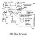
- Fig. 6 illustrates a system for alerting rescue services using a location of mobile phones and transmitting location information through an external information center.
- POTS Plain Old Telephone Service or Post Office Telephone Service
- ISDN Integrated Services Digital Network
- PLM network operator 650 Public Land Mobile
- information center 660 which may optionally be connected to a modem 670.
- Fig. 6 shows a system for locating a mobile station 610 as an example of alerting emergency services in the event of an emergency call.
- an emergency call is sent, which is forwarded via the wireless mobile radio network 620 (PLM network) and the wired network 630 (POTS / ISDN network) to a rescue coordination center 640.
- PLM network wireless mobile radio network
- POTS / ISDN network POTS / ISDN network
- the information center can have a database with information about the network infrastructure.
- the passing on of the location information can also be effected via another data transmission technique, such as e.g. by fax or e-mail, etc., whereby the IT center 660 can then have a corresponding modem 670.
- TA timing advance
- BTS Base Transceiver Station
- MS Mobile Station
- T b whole bit periods
- TA can also be the effective distance d ⁇ ( TA + 0 . 5 ) ⁇ 554 ⁇ m to calculate.
- the inaccuracy corresponding to the quantization of the TA is about 277m.
- TA 1, for example, it follows that the mobile station is at a distance d of about 277m ⁇ d ⁇ 831m from the base station. Due to reflections and diffraction, the path of the electromagnetic wave may become larger than the actual distance between MS and BTS, so that the distance d in our example may also be slightly smaller than 277m. In TDD UMTS networks, a similar value is determined.
- RSSI Receiveiver Signal Strength Indicators
- BCCH Broadcast Control Channel, control channel in the GSM
- the Fig. 7 shows a diagram which assigns receive powers p e in dB RSSI values.
- the weights g i, x, g i, y are all the same.
- the weights g i, x , g i, y are selected in the order of the received powers downwards with constant differences between the individual weights.
- the weights are determined directly from the measured reception powers.
- a change in received power of 1 dB means a change in the distance between base station transceiver and mobile station by a factor of 1.06-1.13.
- the weights of the weaker receivable base station transceivers may become smaller by the same amount. 5. From a prediction of the received powers in the environment of the base station transceivers obtained via a propagation model, it is possible to determine the probability density with which the mobile telephone is located at a specific location. The desired position of the mobile station can be determined from the superposition of the probability densities of the individual base station transceivers that can be received in the mobile station.
- the present invention provides a device for determining the position of a mobile radio terminal, comprising means for providing received level measurements of a plurality of base station transceivers, wherein a base station transceiver has a base station transceiver position and supplies a cell range with a cell range position with radio signals in that radio reception is dominated by a radio signal of the base station transceiver compared to radio signals of other base station transceivers, the cell area location being different from the base station transceiver location and being in the cell area.
- the apparatus further comprises means for determining the position of the mobile station based on a combination of the cell area positions of the base station transceivers.
- the present invention is based on the core idea that a position of a mobile radio terminal can be determined more accurately if, instead of the coordinates of the receivable base stations, a position in their cell range is taken into account. For example, a virtual center of gravity of the geometric coverage area of a mobile radio cell could be used.
- a virtual center of gravity of the geometric coverage area of a mobile radio cell could be used.
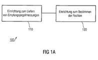
- the Fig. 1a shows a device 100 for determining the position of a mobile radio terminal with a device 110 for providing received level measurements of a plurality of base station transceivers, wherein a base station transceiver has a base station transceiver position and a cell range with a cell range position supplied with radio signals in that a radio reception is dominated by a radio signal of the base station transceiver compared to radio signals of other base station transceivers, the cell range position being different from the base station transceiver position and being in the cell range.
- the apparatus 100 further comprises means 120 for determining the position of the mobile station based on a combination of the cell area positions of the base station transceivers.
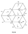
- Fig. 1b an arrangement of three base station transceivers 150, 160 and 170.
- Each of the in the Fig. 1b shown base station transceiver supplies three cell areas with radio signals, ie that a mobile station located in one of these areas, is logged in the corresponding cell area, for example, as a control signal of the base station transceiver, which is dedicated to this cell, is most receptive or dominant in this cell range.
- the base stations transceiver 160 will have the cell areas 162, 164 and 166, and for the base station transceiver 170 the cell areas 172, 174 and 176. Further, in the Fig. 1b recognizable that the three base station transceivers 150, 160 and 170 have three different base station transceiver positions, each in the middle of the supplied cell areas.
- the position determination of a mobile radio terminal is not based on the base station transceiver positions but on cell range positions that lie within the supplied cell ranges.
- the cell area positions 153, 155 and 157 are shown using the example of the base station transceiver 150.
- the cell-site positions 163, 165 and 167 are indicated for the base-station transceiver 160 and the cell-area positions 173, 175 and 177 for the base station transceiver 170.
- a mobile station whose location is to be determined and which is logged into the cell area 152 is unlikely to turn on the base station transceiver position.
- Such a mobile station may be located anywhere in the cell area 152.
- the mobile station will likely be closer to the cell area position 153 than to the base station transceiver position. For this reason, embodiments of the present invention may determine cell station position estimates for mobile stations whose expected estimation errors are well below the expected estimation errors of conventional systems or methods.
- the position determining means 120 may be configured to take into account a cell range position in the combination that is closer to a centroid of a cell area of a base station transceiver than to the base station transceiver position the base station transceiver is arranged.
- the cell area positions are selected in the form of the geometric centroids of the cell areas. This point could be determined, for example, by minimizing an expected estimation error.
- position determining means 120 may also be configured to account for cell range positions of such cell ranges in combination supplied with radio signals from a base station transceiver and in which the base station transceiver radio signals comprise the base station transceiver Radio signals from other base station transceivers are dominated by higher received power, greater signal-to-noise or signal-to-noise and interference ratio.
- the cell areas can therefore be directed to a receivable signal quality.
- the cell shape may result from receivable control signals of a base station transceiver, wherein the control signals of the various base station transceivers and cell areas are compared, and a location is assigned to the cell area whose signal is dominant ,
- the position determining means 120 may consider weighting information in the combination of the cell area positions of the cell areas of the base station transceivers, wherein the weighting information may depend on the received level measurements. In other embodiments weighting information can be taken into account in the position determination, which is such from Depending on the reception level measurements, a cell area position of a cell area of a base station transceiver which provides a high value in the reception level measurement more strongly affects the position of the mobile station than a cell area position of a cell area of a base station transceiver which has a low value in the base station transceiver Receiving level measurement supplies.
- the means 110 for providing the received level measurements may be configured to provide as received level measurement a value normalized to a transmit power or an antenna characteristic of a base station transceiver.
- the directivity of the antennas used at base station transceivers may be taken into account.
- different services of control channels can be taken into account in the position determination.
- the device 120 may further be configured to determine the position of the mobile radio terminal in order to determine a coordinate of the mobile radio terminal according to equation (6), wherein cell area positions are used instead of the base station transceiver positions.
- the device 120 for determining the position of the mobile radio terminal can be designed to determine the position of the mobile radio terminal in two or three spatial coordinates.
- means 120 for determining the position of the mobile station may be configured to select all weighting factors equally.
- the weighting factors of the cell area positions may be selected according to their receive level measurements down with constant differences between the individual weights.
- the weighting ratios of the individual cell area positions may be selected according to the ratios of the received level measurements.
- the device 120 for determining the position of the mobile radio terminal may, in further embodiments, also be designed to determine a probability density of a position of the mobile radio terminal according to a propagation model for a base station transceiver and to determine the position of the mobile radio terminal from a superposition of the probability densities for the base station transceiver. To determine the transceiver. Furthermore, information about past reception level measurements for determining the position of the mobile radio terminal can be taken into account. In addition, it is conceivable to consider a movement speed of a mobile radio terminal in the determination of the position. Also, a relative position determination, i. a position of a mobile station relative to a known position may be performed in embodiments.
- the means 110 for providing received level measurements may be further configured in embodiments to measure relative received level measurements or received level changes, and the means 120 for determining the position of the mobile radio terminal may be further configured be to determine the position of the mobile station based on the relative received level measurements or received level changes.
- the means for providing received level measurements may include receive level measurements from GSM base station transceivers, UMTS base station transceivers, WLAN base station transceivers (WLANs), BlueTooth transceivers, etc. to deliver. Furthermore, it is conceivable that receive level measurements are taken into account by base station transceivers operating in different frequency bands, the means 110 for providing then being designed accordingly.
- the means 110 for providing the received level measurements may be configured to provide signal transit times to the base station transceivers in addition to the received level measurements and the means 120 for determining the position of the mobile station may be configured to adjust the signal propagation times in determining the position of the mobile station Mobile terminal to be considered.
- Embodiments of the present invention may include base station transceivers having a corresponding position determining device.
- Other embodiments include a network element of a mobile network in which a corresponding device 100 is present.
- embodiments of the present invention may also be implemented in a mobile radio terminal.
- embodiments of the present invention may provide for evaluating the locations of virtual centroids of radio cells with an evaluation of information about many surrounding base station transceivers to combine.
- information about the network infrastructure can be collected and used to determine the weights g i, x and g i, y used in equation (6).
- the mobile station's coordinates (x MS , y MS ) are not used as coordinates for the base stations BTS i (x BTSi , y BTSi ).
- coordinates (X BTSi, k ), Y BTSi, k ) of a virtual center of gravity of a cell sector or a cell area BTS i, k may be used, from the transceiver antenna of which the mobile phone receives the corresponding radio signals.
- Fig. 1c shows another example of a mobile network.
- the Fig. 1c shows three base station transceivers BTS1, BTS2 and BTS3.
- Fig. 1c shows the three base stations BTS1, BTS2 and BTS3 in the vicinity of a mobile phone MS.
- the base stations use directional antennas.
- the first antenna of the base station BTS3 radiates in a northerly direction and thus covers a cell C3,1, which is located primarily in the northern sector of BTS3.
- a compass rose is shown in the lower left area and an arrow in the upper left area, which should show an example to the north.
- the cell range of cell C3,1 is in the Fig.
- the expected value of a distance of a mobile station MS located in the cell C3,1 and checked in by the north radiating antenna of BTS3 is the actual position (x BTS3 , y BTS3 ) of BTS3, greater than the expected value of the distance of the mobile station MS to the virtual center of gravity V-BTS3, 1 in cell C3,1.
- the other antennas of the base stations BTS1, BTS2 and BTS3 also irradiate cells or cell areas whose virtual centroids can be described by corresponding coordinates (x BTSi, k , y BTSi, k ) and which are described in US Pat Fig. 1c drawn accordingly and are designated.
- a virtual cell focus There are several ways to determine a virtual cell focus. For example, it is possible to walk the area around a base station antenna and, in a discrete-space spare model, to measure by measurements the points that lie within a cell. Such measurements can be used to determine or estimate cell boundaries. After the boundaries of a cell surface have been determined, the geometric center of gravity of the surface can be determined and used as a virtual cell centroid.
- the measuring method for determining the cell centers of gravity is very complicated, it is also conceivable to use a different method by which estimated values of cell centers are determined.
- estimates of the centers of gravity are then used as virtual cell centroids.
- the cell of a directional base station antenna has the shape of a circular sector of radius R, and that the cell center of gravity is located on a beam from the base station antenna in the direction of the main beam direction of the base station antenna.
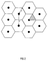
- the cellular mobile network is assumed to be hexagonal cells, as in US Pat Fig. 2 are shown.
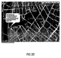
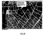
- FIGS. 3a to 3g a position determination of a mobile station considered under realistic conditions in a mobile network.
- the FIGS. 3a to 3g show map sections of the city of Duisburg.
- cell ID cell identification, cell identification
- RSSI Received Signal Strength Indicator
- CI Cell identification, cell identification
- the positions of the base station transceiver antennas can be assigned.
- various estimation methods for determining the position of a mobile station can be used. Simultaneously with the measurement of the received power levels (RSSI), the position of the mobile station can be documented by means of a GPS (Global Positioning System) mouse (GPS). According to this documentation, a mobile station 300 was at 6:42:18 pm on June 13, 2007, at 6.7839 ° east longitude and 51.4284 ° north latitude.
- GPS Global Positioning System
- a mobile station 300 was at 6:42:18 pm on June 13, 2007, at 6.7839 ° east longitude and 51.4284 ° north latitude.
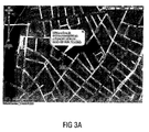
- the measurement and estimation data are shown below on Google Maps maps, with the Fig. 3a indicates the position of the mobile station 300 and the GPS position with the corresponding time stamp also in the map of Fig. 3a is specified.
- the radio signals from three surrounding base station transceiver antennas can be received and their CI, LAC and RSSI read out.
- the three base station antennas are referred to below as BTS00, BTS03 and BTS05.
- the FIGS. 3b . 3c and 3d each show in a map section the arrangements of the base station transceivers BTS00, BTS03 and BTS05, and the GPS position of the mobile station 300.
- Fig. 3b additionally shows the position direction and receive data of the BTS00, the Fig. 3c the BTS03 and the Fig. 3d the BTS05.
- the received power levels RSSI with which the control channels of the base station transceiver antennas were received by the mobile station 300 are indicated in the corresponding data sets in the form of the RSSI values, as well the positions of the base station transceivers and the main beam directions ("azimuth") of the base station transceiver antennas.
- the angle “azimuth” is the angle of the main beam direction, which lies between the north of the graph and the main beam direction of a base station transceiver antenna, measured in clockwise direction in degrees.
- an estimated position 310 of the mobile station which results when the method according to the invention is used in an embodiment for position determination.
- the mobile station was BTS00-in and received the signal from BTS00 at higher power than the signal from the closer base station transceiver BTS03.
- Reason for this could have been, for example, that the mobile station 300 at this time was heavily shadowed by a building to the east.
- Such scenarios, where highly uneven shading may result in a mobile station not being logged in to the nearest base station transceiver, can often result, especially in urban areas.
- the FIG. 3e indicates an estimated position 320, which results when the position of the mobile station is estimated at the position where the base station transceiver antenna is located, at which the mobile station is registered.
- the estimation error is 444m.
- the Fig. 3f shows an estimated position 300, which results when the position of the mobile station 300 is determined by averaging the positions of surrounding base stations.
- the position of BTS05 was here with the weight 1/6, the position of BTS03 with the weight 2/6 and the position of BTS05 with 3/6 weighted. In this case, the estimation error is 217m.
- the Fig. 3g Figure 11 shows the estimated position 310 again, which results when the position of the mobile station 300 is determined by averaging the positions of the virtual centroid.
- the position of the virtual cell center of BTS05 was weighted 1/6
- the position of the virtual cell center of BTS03 was weight 2/6
- the position of the virtual cell center of BTS05 was 3/6. In this case the estimation error is only 113m.
- the embodiment which in this case uses the virtual centroids of the cell ranges for position determination best performs. That in the Fig. 3f The method used does not take into account that the base station antenna of the BTS05 radiates in a southeasterly direction and BTS03 in a southwesterly direction. At the in Fig. 3f estimated position 330 might be expected to receive radio signals from the northern sectors of the base station transceivers in the locations of BTS03 and BTS05. This consideration clearly shows the strength of the embodiments, which can perform, for example, a position averaging based on the virtual centers of gravity.
- FIGS. 3a to g not an isolated case.
- the Fig. 4 again shows a Google Maps map in which the route 400 is drawn one of these measurement data.
- the points shown on Route 400 are derived from GPS coordinates read out of a GPS mouse during the test drive.
- Different estimation methods were applied to the collected measurement data. For each estimation method, the estimation errors were determined as the absolute distance between the estimated position and the actual position. Actual positions were assumed to be the positions resulting from the GPS coordinates.
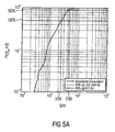
- Fig. 5a is the relative incidence that a particular estimation error has not been exceeded for the method of linearly weighting the base station transceiver positions, as it did for the Fig. 3f was used, applied.
- the line 550 marks the estimation error, which was not exceeded in 50% of the cases
- the line 590 marks the estimation error, which was not exceeded in 90% of cases.
- the data were evaluated, which according to Fig. 4 were collected. In 50% of cases, the error was less than or equal to 241.2941m. In 90% of cases, the measurement error was less than or equal to 447.6m.
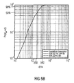
- the Fig. 5b Figure 4 shows the relative frequency of not exceeding a certain estimation error for an embodiment that used a linear weighting of the virtual centroids for position estimation.
- Analogous to Fig. 5a the data of those measuring points were evaluated, which were used in the Fig. 4 shown test drive were collected.
- the line 550 again marks the estimation error that was not exceeded in 50% of all cases
- the line 590 marks again the estimated value, which was not exceeded in 90% of the cases. In 50% of cases the error was less than or equal to 176.9375m, in 90% the error was less than 344.8333m.
- FIGS. 5a and 5b clearly document the advantage or gain in accuracy that embodiments of the present invention provide over conventional positioning methods.
- other methods are conceivable in addition to the method considered here, for example those which weight the virtual centers of gravity of the cells differently.
- positions of the base stations could be weighted differently than those in the Fig. 3f was shown. However, if one sticks to the base station transceiver positions, no increase in accuracy is expected.
- the virtual center of gravity of a radio cell in which the mobile telephone is registered could also initially be assumed to be the estimated position.
- this position would be inaccurate, on the other hand more accurate than a method emanating from the base station transceiver positions.
- the mobile station may also provide or take into account information about historical measurements, thus, for each past time for which measurements are taken, the location of the mobile station may be determined. Because of the expected low movement speeds of the mobile station, the true positions of temporally adjacent measured values are not far apart lie. By a suitable averaging of the calculated positions taking into account the determination of a movement speed, the true position can be determined more accurately than if only one set of measured values is evaluated at a time.
- Embodiments consider cell range locations that differ from the base station transceiver positions, such as the virtual centroids of the cell ranges.
- the measurements have shown that embodiments of the present invention can provide a significant gain in accuracy.
- profits in the accuracy of a position determination often express themselves in a time gain in finding an in distress.
- Embodiments therefore contribute in emergencies to provide assistance by rescue workers faster.
- the inventive scheme can also be implemented in software.
- the implementation can be carried out on a digital storage medium, in particular a floppy disk, a CD or a DVD with electronically readable control signals, which can interact with a programmable computer system such that the corresponding method is carried out.
- the invention thus also consists in a computer program product with program code stored on a machine-readable carrier for carrying out the method according to the invention when the computer program product runs on a computer.
- the invention can thus be implemented as a computer program with a program code of the method can be realized when the computer program product runs on a computer.
Landscapes
- Physics & Mathematics (AREA)
- Engineering & Computer Science (AREA)
- General Physics & Mathematics (AREA)
- Radar, Positioning & Navigation (AREA)
- Remote Sensing (AREA)
- Mobile Radio Communication Systems (AREA)
Applications Claiming Priority (1)
| Application Number | Priority Date | Filing Date | Title |
|---|---|---|---|
| DE102007038696A DE102007038696A1 (de) | 2007-08-16 | 2007-08-16 | Vorrichtung und Verfahren zur Positionsbestimmung eines Mobilfunkendgerätes |
Publications (2)
| Publication Number | Publication Date |
|---|---|
| EP2026089A2 true EP2026089A2 (fr) | 2009-02-18 |
| EP2026089A3 EP2026089A3 (fr) | 2009-03-25 |
Family
ID=39938267
Family Applications (1)
| Application Number | Title | Priority Date | Filing Date |
|---|---|---|---|
| EP08014244A Withdrawn EP2026089A3 (fr) | 2007-08-16 | 2008-08-08 | Dispositif et procédé destinés à la détermination de la position d'un appareil hertzien mobile |
Country Status (2)
| Country | Link |
|---|---|
| EP (1) | EP2026089A3 (fr) |
| DE (1) | DE102007038696A1 (fr) |
Families Citing this family (1)
| Publication number | Priority date | Publication date | Assignee | Title |
|---|---|---|---|---|
| JP6497210B2 (ja) * | 2015-05-22 | 2019-04-10 | ダイキン工業株式会社 | 位置推定システム |
Citations (3)
| Publication number | Priority date | Publication date | Assignee | Title |
|---|---|---|---|---|
| US5670964A (en) | 1993-09-09 | 1997-09-23 | Ericsson Inc. | Navigation assistance for call handling in mobile telephone systems |
| WO2004016032A1 (fr) | 2002-08-08 | 2004-02-19 | Qualcomm Incorporated | Determination de la position par zone des terminaux d'un reseau sans fil |
| WO2004049632A1 (fr) | 2002-11-27 | 2004-06-10 | Koninklijke Philips Electronics N.V. | Unite, systeme et procede de localisation |
Family Cites Families (2)
| Publication number | Priority date | Publication date | Assignee | Title |
|---|---|---|---|---|
| EP1521490A1 (fr) * | 2004-03-29 | 2005-04-06 | Siemens Aktiengesellschaft | Procédé et dispositif pour déterminer la position d'un terminal mobile dans un système de communication mobile |
| EP1937021A3 (fr) * | 2006-12-18 | 2008-08-13 | Björn Steiger Stiftung Service GmbH | Dispositif et procédé destinés à la détermination de la position d'un appareil hertzien mobile |
-
2007
- 2007-08-16 DE DE102007038696A patent/DE102007038696A1/de not_active Withdrawn
-
2008
- 2008-08-08 EP EP08014244A patent/EP2026089A3/fr not_active Withdrawn
Patent Citations (3)
| Publication number | Priority date | Publication date | Assignee | Title |
|---|---|---|---|---|
| US5670964A (en) | 1993-09-09 | 1997-09-23 | Ericsson Inc. | Navigation assistance for call handling in mobile telephone systems |
| WO2004016032A1 (fr) | 2002-08-08 | 2004-02-19 | Qualcomm Incorporated | Determination de la position par zone des terminaux d'un reseau sans fil |
| WO2004049632A1 (fr) | 2002-11-27 | 2004-06-10 | Koninklijke Philips Electronics N.V. | Unite, systeme et procede de localisation |
Also Published As
| Publication number | Publication date |
|---|---|
| EP2026089A3 (fr) | 2009-03-25 |
| DE102007038696A1 (de) | 2009-02-19 |
Similar Documents
| Publication | Publication Date | Title |
|---|---|---|
| EP2335442B1 (fr) | Dispositif et procédé d'estimation d'une orientation d'un terminal mobile | |
| DE69837389T2 (de) | Verfahren und system zur positionsbestimmung von mobilen funkendgeräten | |
| DE60209051T2 (de) | Positionsbestimmung eines Mobilkommunikationsendgeräts aufgrund einer Kombination von Messungen von zwischen dem Mobilkommunikationsendgerät und Basisstationen ausgetauschten Signalen | |
| DE60301392T2 (de) | Sender lokalisierungssystem | |
| DE69429472T2 (de) | Verfahren zur Aufenthaltsortbestimmung von mobilen Stationen in einem digitalen Telefonnetzwerk mit der Hilfe von einem trainiert neuralen Netzwerk | |
| EP1606965B1 (fr) | Procede et dispositif pour adapter un modele de reseau radio aux conditions d'un reseau radio reel | |
| DE102004035531B4 (de) | Vorrichtung und Verfahren zum Ermitteln einer aktuellen Position eines mobilen Gerätes | |
| WO2003086005A1 (fr) | Procede, dispositif, programme informatique comportant des elements de code de programme et produit de programme destines a determiner une position d'un appareil de communication mobile dans un reseau de communication | |
| DE10196828T5 (de) | Dual-Modus-Uplink/Downlink-Positionsmessung und Multi-Protokoll-Positionsmessung | |
| DE102014119708A1 (de) | Verfahren zur Bestimmung des Standorts drahtloser Vorrichtungen | |
| DE112022002067T5 (de) | Mobilfunkbasierte positionsbestimmung unter verwendung von messungen der empfangenen signalleistung und der zeit | |
| DE102014119709A1 (de) | Verfahren zur Bestimmung des Standorts drahtloser Vorrichtungen | |
| DE102006056338A1 (de) | Verfahren und Vorrichtung zur Bestimmung der Position eines Endgeräts in einem Mobilfunknetz | |
| DE69705931T2 (de) | Positionsbestimmung eines endgerätes mittels mehrerer strahlungskeulen | |
| DE10142954B4 (de) | Verfahren zur Ortung mit einem mobilen Endgerät | |
| DE19948556A1 (de) | Verfahren und Vorrichtungen zum Orten eines Mobilempfängers mittels Abwärtsstreckensignalen | |
| EP2026089A2 (fr) | Dispositif et procédé destinés à la détermination de la position d'un appareil hertzien mobile | |
| EP2026088A2 (fr) | Dispositif d'évaluation d'une position d'arrêt d'un appareil hertzien mobile | |
| DE102013211130B4 (de) | Verfahren zur Berechnung von Übergabeparametern für ein Kommunikationsgerät, Verfahren zur Kommunikation und Kommunikationsgerät hierfür | |
| DE102007061677B4 (de) | Verfahren zur Positionsbestimmung eines mobilen Funk-Kommunikationsendgeräts | |
| DE102004043534A1 (de) | Verfahren zum Bestimmen des Aufenthaltsortes einer Teilnehmerstation eines Funkkommunikationssystems | |
| DE102024133808B3 (de) | Messung der Ausbreitungsbedingungen von Hochfrequenzsignalen | |
| EP1555845A1 (fr) | Procédé de localisation des postes d'abonnés d'un système de communication radio | |
| WO2003098951A1 (fr) | Procede de determination de position d'une station mobile et unite de determination de position | |
| EP2555554B1 (fr) | Appareil et procédé de détection de manques d'entretien dans un réseau |
Legal Events
| Date | Code | Title | Description |
|---|---|---|---|
| PUAI | Public reference made under article 153(3) epc to a published international application that has entered the european phase |
Free format text: ORIGINAL CODE: 0009012 |
|
| AK | Designated contracting states |
Kind code of ref document: A2 Designated state(s): AT BE BG CH CY CZ DE DK EE ES FI FR GB GR HR HU IE IS IT LI LT LU LV MC MT NL NO PL PT RO SE SI SK TR |
|
| AX | Request for extension of the european patent |
Extension state: AL BA MK RS |
|
| PUAL | Search report despatched |
Free format text: ORIGINAL CODE: 0009013 |
|
| AK | Designated contracting states |
Kind code of ref document: A3 Designated state(s): AT BE BG CH CY CZ DE DK EE ES FI FR GB GR HR HU IE IS IT LI LT LU LV MC MT NL NO PL PT RO SE SI SK TR |
|
| AX | Request for extension of the european patent |
Extension state: AL BA MK RS |
|
| RIC1 | Information provided on ipc code assigned before grant |
Ipc: H04W 64/00 20090101ALI20090216BHEP Ipc: G01S 5/14 20060101ALI20090216BHEP Ipc: G01S 5/02 20060101AFI20081112BHEP |
|
| 17P | Request for examination filed |
Effective date: 20090924 |
|
| RAP1 | Party data changed (applicant data changed or rights of an application transferred) |
Owner name: ALLIANZ ORTUNGSSERVICES GMBH |
|
| AKX | Designation fees paid |
Designated state(s): AT BE BG CH CY CZ DE DK EE ES FI FR GB GR HR HU IE IS IT LI LT LU LV MC MT NL NO PL PT RO SE SI SK TR |
|
| 17Q | First examination report despatched |
Effective date: 20110307 |
|
| STAA | Information on the status of an ep patent application or granted ep patent |
Free format text: STATUS: THE APPLICATION IS DEEMED TO BE WITHDRAWN |
|
| 18D | Application deemed to be withdrawn |
Effective date: 20110301 |