EP2026445A2 - Machine synchrone à ondulation de couple réduite - Google Patents
Machine synchrone à ondulation de couple réduite Download PDFInfo
- Publication number
- EP2026445A2 EP2026445A2 EP08104933A EP08104933A EP2026445A2 EP 2026445 A2 EP2026445 A2 EP 2026445A2 EP 08104933 A EP08104933 A EP 08104933A EP 08104933 A EP08104933 A EP 08104933A EP 2026445 A2 EP2026445 A2 EP 2026445A2
- Authority
- EP
- European Patent Office
- Prior art keywords
- magnetic flux
- stator core
- pole tooth
- synchronous machine
- rotor
- Prior art date
- Legal status (The legal status is an assumption and is not a legal conclusion. Google has not performed a legal analysis and makes no representation as to the accuracy of the status listed.)
- Withdrawn
Links
Images


Classifications
-
- H—ELECTRICITY
- H02—GENERATION; CONVERSION OR DISTRIBUTION OF ELECTRIC POWER
- H02K—DYNAMO-ELECTRIC MACHINES
- H02K1/00—Details of the magnetic circuit
- H02K1/06—Details of the magnetic circuit characterised by the shape, form or construction
- H02K1/12—Stationary parts of the magnetic circuit
- H02K1/14—Stator cores with salient poles
- H02K1/146—Stator cores with salient poles consisting of a generally annular yoke with salient poles
-
- H—ELECTRICITY
- H02—GENERATION; CONVERSION OR DISTRIBUTION OF ELECTRIC POWER
- H02K—DYNAMO-ELECTRIC MACHINES
- H02K1/00—Details of the magnetic circuit
- H02K1/06—Details of the magnetic circuit characterised by the shape, form or construction
- H02K1/22—Rotating parts of the magnetic circuit
- H02K1/27—Rotor cores with permanent magnets
- H02K1/2706—Inner rotors
- H02K1/272—Inner rotors the magnetisation axis of the magnets being perpendicular to the rotor axis
- H02K1/274—Inner rotors the magnetisation axis of the magnets being perpendicular to the rotor axis the rotor consisting of two or more circumferentially positioned magnets
- H02K1/2753—Inner rotors the magnetisation axis of the magnets being perpendicular to the rotor axis the rotor consisting of two or more circumferentially positioned magnets the rotor consisting of magnets or groups of magnets arranged with alternating polarity
- H02K1/276—Magnets embedded in the magnetic core, e.g. interior permanent magnets [IPM]
-
- H—ELECTRICITY
- H02—GENERATION; CONVERSION OR DISTRIBUTION OF ELECTRIC POWER
- H02K—DYNAMO-ELECTRIC MACHINES
- H02K29/00—Motors or generators having non-mechanical commutating devices, e.g. discharge tubes or semiconductor devices
- H02K29/03—Motors or generators having non-mechanical commutating devices, e.g. discharge tubes or semiconductor devices with a magnetic circuit specially adapted for avoiding torque ripples or self-starting problems
Definitions
- the invention generally relates to a synchronous machine, in particular as a drive for a power steering system of a motor vehicle.
- the invention relates in particular to a stator core for such a synchronous machine.
- Such a synchronous machine comprises a rotor rotatably arranged in a stator, in which by means of a number of permanent magnets, a permanent magnetic exciter field is generated.
- the stand usually comprises a stator core made of an electrical sheet with an approximately hollow cylindrical shell, from which a number of pole teeth protrude inward in the direction of the rotor in a spoke-like manner.
- the pole teeth are wound with phase windings.
- this torque always has a certain waviness, ie fluctuates depending on the rotor rotation angle.
- a supported by a synchronous machine steering runs as a result of this torque ripple - colloquially expressed - to some extent "out of round” or "hooked", which is unsatisfactory in terms of ride comfort.
- the Torque ripple may also cause unwanted noise during operation of the power steering.
- the invention has for its object to improve a synchronous machine with simple means to the effect that during operation of the machine, a particularly low torque ripple occurs.
- stator core provided for a synchronous machine with a substantially hollow cylindrical shell and a plurality of radially projecting from the inner circumference of the shell of the spokes radially inwardly projecting pole teeth to the effect that in each pole tooth at least a magnetic flux barrier is provided.
- each magnetic flux barrier is preferably arranged close to a radially inner end of the respective associated pole tooth.
- each pole tooth expediently has two magnetic flux barriers, which are arranged symmetrically with respect to a radial-axial center plane of the pole tooth and in each case close to the opposite side walls of the pole tooth, so that a distance is formed between each magnetic flux barrier and the center plane. which substantially exceeds the distance of the magnetic flux barrier to the respective adjacent side wall of the pole tooth.
- each pole tooth expediently has a comparatively thin neck in the profile and at its radially inner end on the opposite side of the neck in the circumferential direction widened head on both sides.
- Each pole tooth thus has in profile approximately the shape of a letter "T" on the frame.
- the portions of the head projecting beyond the neck as a result of the broadening in the two-sided circumferential direction are referred to below as "protrusions”.
- stator core it has proved to be particularly advantageous to provide (at least) one magnetic flux barrier in the region of each projection.
- the magnetic flux barriers are in particular completely withdrawn into the respective projection, so that the magnetic flux barriers in the radial direction do not overlap with the neck of the associated pole tooth.
- Each magnetic flux barrier preferably has an approximately circular or oval cross-section. If the magnetic flux barrier is provided with an oval cross-section, then it is preferably aligned with its maximum diameter radially with respect to the stator core.
- Each magnetic flux barrier is formed in a simple and expedient embodiment by a hollow recess in the material of the associated pole tooth, in particular by a bore.
- the magnetic flux barrier may also be formed by an embedding of a non-magnetic material, in particular a plastic, a ceramic or a non-ferromagnetic metal.
- a distance of at least 0.2 mm is formed between each magnetic flux barrier and a next adjacent wall of the associated pole tooth.
- each pole tooth is connected to the radially inner ends of the respective adjacent pole teeth, so that the inner ends of the pole teeth in the profile Form with the mantle concentric inner ring.
- a synchronous machine in which both stator and rotor are provided with magnetic flux barriers.
- the stator in this case comprises a stator core of the type described above.
- the rotor arranged rotatably in the stator comprises a rotor core with a plurality of permanent magnets embedded therein.
- On the rotor side in each case at least one magnetic flux barrier is arranged between each permanent magnet and an air gap formed between the rotor and the stator.
- the magnetic flux barriers arranged in the rotor laminations here preferably each have a substantially circular cross section.
- the magnetic flux barriers arranged on the rotor side are furthermore, analogously to the magnetic flux barriers arranged in the stator core, expediently by a hollow recess formed in the Läufererblechonce or by a deposit of non-magnetic material.
- At least two, in particular four magnetic flux barriers are arranged between each permanent magnet of the rotor and the air gap, wherein a distance of at least 1 mm is formed in appropriate dimensioning between each two of these magnetic flux barriers.
- the magnetic flux barriers arranged in the rotor core are, in addition to or as an alternative to the above dimensioning rule, preferably at a distance of at least 0.2 mm from the surrounding air gap.
- the synchronous machine described above is preferably used as a drive for a motor vehicle power steering.
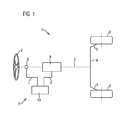
- FIG. 1 roughly schematically illustrated motor vehicle steering system 1 (hereinafter referred to as steering system 1) comprises a steering wheel 2 which acts on a steering rod 4 via a steering column 3 (not shown in the drawing) and a steering gear (not explicitly shown).
- the steering rod 4 is coupled on both sides via a respective steering lever 5 articulated to the suspension of a respective corresponding wheel 6, so that in a conventional manner by rotation of the steering wheel 2, an impact of the wheels 6 can be effected.
- the steering 1 is also equipped with an electrically operated power steering 7.
- the power steering 7 comprises a torque sensor 8, which is arranged in or on the steering column 3 and measures the steering torque L exerted by the steering wheel 2 on the steering column 3.
- the drive of the power steering 7 forms an electric motor 9, which is operatively coupled to the steering column 3.
- the power steering system 7 comprises a control unit 10, which evaluates the steering torque L, which is measured by the torque sensor 8, and drives the electric motor 9 as a function of this evaluation by emitting a control signal C.
- the control of the electric motor 9 is carried out in a conventional manner such that the electric motor 9 exerts an auxiliary torque on the steering column 3, which partially compensates for the steering torque L and thus supports the steering force applied to the steering wheel 2.
- the power steering 7 can also be used as an automatic steering.
- the control unit controls 10, the electric motor 9 regardless of the steering torque L on.
- the steering wheel 2 can also be omitted in this embodiment.
- a further electric motor (which is substantially corresponding thereto and not explicitly shown) may be coupled to the steering rod 4, which is likewise controlled by the control unit 10.
- FIG. 2 illustrated in a schematic cross section electric motor 9 is designed as a permanent magnet synchronous machine. It comprises a rotor 12 rotatably mounted about an axis of rotation 11.
- the rotor 12 comprises an approximately cylindrical laminated core 13 made of a so-called electrical sheet.
- eight pocket-like recesses 14 are introduced, which complement each other in cross-section approximately to the edge of a uniform octagon.
- Each recess 14 serves for receiving and holding a permanent magnet 15, wherein the permanent magnets 15 are distributed in alternately alternating polarity over the circumference of the rotor 12.
- the laminated core 13 has a convexity convexly convex in each case in the area radially outward of each permanent magnet 15, deviating from an ideal cylindrical shape ,
- the radius of the rotor 12 thereby varies in the circumferential direction of the rotor 12 periodically between a minimum and a maximum value, wherein the minimum value in each case in the region between two permanent magnets 15 and the maximum value in each case in the Polmitte, i. is assumed in the region of the radial-axial center plane of each permanent magnet 15.
- the electric motor 9 further comprises a stator 17 surrounding the rotor 12.
- the stator 17 comprises a stator core 18 made of an electrical steel sheet.
- the stator core 18 comprises a hollow cylindrical jacket 19, from the inner circumference of a Number of - in the example shown twelve - pole teeth 20 in the manner of spokes radially inwardly towards the rotor 12 protrude.
- the pole teeth 20 are (in a manner not explicitly shown) each wound with a phase coil.
- Each pole tooth 20 comprises a collar 21, which is comparatively narrow in cross-section.
- a neck 22 opposite, and thus radially inner, end 22 of each pole tooth 20 is formed into a head 23 symmetrically widened in the circumferential direction relative to the neck 21.
- the sections of the respective pole tooth projecting beyond the neck 21 as a result of this widening in the circumferential direction are designated as projections 24.
- the heads 23 of adjacent pole teeth 20 are each spaced apart in the circumferential direction.
- the stator grooves formed between each two adjacent pole teeth 20 are inward, and thus open to the rotor 12.
- both the stator core 18 and the rotor 12 are substantially designed as profile parts, so that the in FIG. 2 illustrated profile substantially over the entire axial length of the electric motor 9 continues.
- FIG. 3 shows in a rough schematic representation generally the drive torque T D of the electric motor 9, plotted against the rotor position R.
- the drive torque T D is the torque referred to, which transfers the rotor 12 during operation of the electric motor 9 to a drive shaft connected thereto.
- As rotor position R the angle of rotation of the rotor 12 is referred to the stator 17.
- the drive torque T D is a fluctuating function of the rotor position R.
- the drive torque T D is therefore characterized by the corresponding amplitude of vibration torque ripple T AC (torque ripple), and by the average value of the vibration corresponding static torque T DC .
- the torque ripple T AC of the electric motor 9 causes the force to be applied by actuation of the steering system 1 to fluctuate with the steering angle, so that the steering runs "out of round” or “hooks” from the perspective of a vehicle user. In order to improve the ease of operation of the steering system 1, it is therefore desirable to minimize the torque ripple T AC .
- each two magnetic flux locks 30 are provided, which in various embodiments in the 4 and FIG. 5 are shown in more detail.
- Each magnetic flux barrier 30 is formed by a hollow bore introduced into the stator core 18 in the axial direction with a circular or slot-like oval cross-section, the magnetic barriers optionally being aligned with the longer side in the radial direction with respect to the stator core 18.
- the two per pole tooth 20 provided magnetic flux barriers 30 are arranged symmetrically to a radial-axial center plane 32 of the pole tooth 20 and completely withdrawn into the projections 24.
- the magnetic flux barriers 30 are thereby arranged in particular close to the radially inner end 22 of the pole tooth 20 and close to the Pohlberger 20 circumferentially bounding side walls.
- each magnetic flux barrier 30 and an inner wall of the pole tooth 20 forming the end 22 is a distance W o of more than 0.2 mm, between each magnetic flux barrier 30 and an adjacent side wall of the head 23, a distance W d of more than 0.2 mm and between each magnetic flux barrier 30 and an outer wall of the head 23, a distance W s formed by more than 0.2 mm.
- W o , W d and W s is incidentally supplemented by the 4 and 5 directed.
- magnetic flux barriers 33 are provided to further reduce the torque ripple T D of the rotor 12 with further magnetic flux barriers 33.
- These magnetic flux barriers 33 are formed by hollow bores of approximately circular cross-section, which are introduced into the laminated core 13. In each case, four magnetic flux barriers 33 are provided per permanent magnet 15. These magnetic flux barriers 33 are arranged between the associated permanent magnet 15 and the outer periphery of the rotor 12 (and thus the air gap 25) close to the outer periphery of the rotor 12.
- two of these magnetic flux locks 33 are arranged symmetrically on both sides of a radial-axial center plane 34 of the respective permanent magnet 15.
- each two adjacent magnetic flux locks 33 each have a distance of W j of 1 mm, between each magnetic flux barrier 33 and the outer circumference of the rotor 12, a distance W r of at least 0.2 mm and between the two outer magnetic flux locks 33 a permanent magnet 15 associated four group of magnetic flux barriers 33 and an adjacent pole end 35 of the permanent magnet 15 a distance W k of at least 0.2 mm formed.
- the permanent magnet 15 is designated in the circumferential direction limiting edge.
- the distances W r , W j and W k is in addition to the 4 and 5 directed.
- FIG. 2 . 4 and 5 Stand 17 shown deviating in combination with a runner with opposite FIG. 2 . 4 and 5 modified magnetic flux barriers or used in combination with a rotor without magnetic flux barriers.
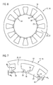
- FIG. 6 shows an alternative embodiment of the stator 17.
- the stator core 18 differs from those associated with the FIG. 2 . 4 and 5 described embodiments in that the head 23 of each pole tooth 20 is connected to the heads 23 of the adjacent pole teeth 20, so that the radially inner end 22 of the pole teeth 20 forms a jacket 19 concentric, closed ring.
- the FIG. 6 shown embodiment of the stator 17 is otherwise similar in connection with FIG. 2 described embodiment.
- two magnetic flux barriers 30 are arranged in the head 23 of each pole tooth 20.
- FIG. 7 A concrete embodiment of the in FIG. 6
- the construction principle shown is in FIG. 7 shown in more detail.
- the adjacent pole teeth 20 in the region of the respective heads 23 are connected by a magnetic flux bridge 36, which bridges are substantially thinner in their radial extent than the heads 23 of the adjacent pole teeth 20.
- the magnetic flux barriers 30 is similar to the embodiment of the in FIG. 7 illustrated stator core 18 otherwise according to the embodiment 4 or 5 ,
- the magnetic flux barriers 30 in a according to FIG. 6 or 7 inside closed stator core 18 also - as in FIG. 5 shown - slit-like oval.
- FIG. 6 or 7 inside closed stator core 18 is in the context of the invention optionally in combination with the in the FIG. 2 . 4 and 5 shown runner 12, with a runner with opposite FIG. 2 . 4 and 5 modified magnetic flux barriers or used in combination with a rotor without magnetic flux barriers.
Landscapes
- Engineering & Computer Science (AREA)
- Power Engineering (AREA)
- Iron Core Of Rotating Electric Machines (AREA)
- Permanent Magnet Type Synchronous Machine (AREA)
Applications Claiming Priority (1)
| Application Number | Priority Date | Filing Date | Title |
|---|---|---|---|
| DE102007038904A DE102007038904A1 (de) | 2007-08-17 | 2007-08-17 | Synchronmaschine mit reduzierter Drehmomentwelligkeit |
Publications (2)
| Publication Number | Publication Date |
|---|---|
| EP2026445A2 true EP2026445A2 (fr) | 2009-02-18 |
| EP2026445A3 EP2026445A3 (fr) | 2017-03-08 |
Family
ID=40130520
Family Applications (1)
| Application Number | Title | Priority Date | Filing Date |
|---|---|---|---|
| EP08104933.0A Withdrawn EP2026445A3 (fr) | 2007-08-17 | 2008-07-31 | Machine synchrone à ondulation de couple réduite |
Country Status (2)
| Country | Link |
|---|---|
| EP (1) | EP2026445A3 (fr) |
| DE (1) | DE102007038904A1 (fr) |
Cited By (3)
| Publication number | Priority date | Publication date | Assignee | Title |
|---|---|---|---|---|
| CN107579612A (zh) * | 2017-08-30 | 2018-01-12 | 广东威灵电机制造有限公司 | 转子冲片、转子铁芯和电机 |
| EP3273581A1 (fr) * | 2016-07-18 | 2018-01-24 | Higenmotor Co., Ltd. | Rotor de moteur électrique à aimant intérieur permanent |
| GB2569142A (en) * | 2017-12-06 | 2019-06-12 | Trw Ltd | An interior permanent magnet motor |
Families Citing this family (2)
| Publication number | Priority date | Publication date | Assignee | Title |
|---|---|---|---|---|
| DE102009048116A1 (de) | 2009-10-02 | 2011-04-07 | Brose Fahrzeugteile GmbH & Co. Kommanditgesellschaft, Würzburg | Bürstenloser Synchronmotor |
| DE102011086280A1 (de) * | 2011-11-14 | 2013-05-16 | Schaeffler Technologies AG & Co. KG | Hochdrehende permanenterregte Synchronmaschine |
Citations (5)
| Publication number | Priority date | Publication date | Assignee | Title |
|---|---|---|---|---|
| JPH10285845A (ja) | 1997-03-31 | 1998-10-23 | Mitsubishi Electric Corp | 永久磁石形モータおよびその製造方法 |
| JPH10285851A (ja) | 1997-04-07 | 1998-10-23 | Mitsubishi Electric Corp | 永久磁石型モータ |
| DE19851883A1 (de) | 1998-11-10 | 2000-05-18 | Siemens Ag | Permanenterregte Synchronmaschine |
| EP0809343B1 (fr) | 1996-05-21 | 2000-11-02 | Siemens Aktiengesellschaft | Machine synchrone excité par aimant permanent |
| JP2004350345A (ja) | 2003-05-20 | 2004-12-09 | Matsushita Electric Ind Co Ltd | 永久磁石電動機 |
Family Cites Families (2)
| Publication number | Priority date | Publication date | Assignee | Title |
|---|---|---|---|---|
| US5250867A (en) * | 1991-11-20 | 1993-10-05 | General Electric Company | Permanent magnet brushless DC motor having reduced cogging |
| JP2006288043A (ja) * | 2005-03-31 | 2006-10-19 | Toshiba Corp | 永久磁石形モータ |
-
2007
- 2007-08-17 DE DE102007038904A patent/DE102007038904A1/de not_active Withdrawn
-
2008
- 2008-07-31 EP EP08104933.0A patent/EP2026445A3/fr not_active Withdrawn
Patent Citations (5)
| Publication number | Priority date | Publication date | Assignee | Title |
|---|---|---|---|---|
| EP0809343B1 (fr) | 1996-05-21 | 2000-11-02 | Siemens Aktiengesellschaft | Machine synchrone excité par aimant permanent |
| JPH10285845A (ja) | 1997-03-31 | 1998-10-23 | Mitsubishi Electric Corp | 永久磁石形モータおよびその製造方法 |
| JPH10285851A (ja) | 1997-04-07 | 1998-10-23 | Mitsubishi Electric Corp | 永久磁石型モータ |
| DE19851883A1 (de) | 1998-11-10 | 2000-05-18 | Siemens Ag | Permanenterregte Synchronmaschine |
| JP2004350345A (ja) | 2003-05-20 | 2004-12-09 | Matsushita Electric Ind Co Ltd | 永久磁石電動機 |
Cited By (6)
| Publication number | Priority date | Publication date | Assignee | Title |
|---|---|---|---|---|
| EP3273581A1 (fr) * | 2016-07-18 | 2018-01-24 | Higenmotor Co., Ltd. | Rotor de moteur électrique à aimant intérieur permanent |
| CN107579612A (zh) * | 2017-08-30 | 2018-01-12 | 广东威灵电机制造有限公司 | 转子冲片、转子铁芯和电机 |
| CN107579612B (zh) * | 2017-08-30 | 2020-01-03 | 广东威灵电机制造有限公司 | 转子冲片、转子铁芯和电机 |
| GB2569142A (en) * | 2017-12-06 | 2019-06-12 | Trw Ltd | An interior permanent magnet motor |
| US10686340B2 (en) | 2017-12-06 | 2020-06-16 | Trw Limited | Interior permanent magnet motor |
| GB2569142B (en) * | 2017-12-06 | 2023-05-03 | Trw Ltd | An interior permanent magnet motor |
Also Published As
| Publication number | Publication date |
|---|---|
| EP2026445A3 (fr) | 2017-03-08 |
| DE102007038904A1 (de) | 2009-03-12 |
Similar Documents
| Publication | Publication Date | Title |
|---|---|---|
| DE60212406T2 (de) | Läufer mit eingebetteten Dauermagneten | |
| EP2483991B1 (fr) | Moteur synchrone sans balai | |
| EP2951909B1 (fr) | Rotor, moteur à réluctance et procédé de fabrication d'un rotor | |
| EP2619883B1 (fr) | Élément pour une machine électrique | |
| EP1495527B1 (fr) | Machine electrique, notamment moteur excite par aimant permanent | |
| DE69827299T2 (de) | Elektrischer motor oder generator | |
| EP1759447B1 (fr) | Machine a champ tournant pourvue d'induits en cloche | |
| EP2639935B1 (fr) | Rotor à excitation permanente, machine électrique dotée d'un tel rotor et procédé de fabrication du rotor | |
| DE69703566T2 (de) | Geschalteter Reluktanzmotor | |
| EP2709238B1 (fr) | Machine synchrone à excitation permanente dotée d'aimants en ferrite | |
| DE102009060438A1 (de) | Rotor mit kurzschlusskäfig | |
| EP2471159A2 (fr) | Rotor à aimants permanents | |
| DE102009029065A1 (de) | Elektrische Maschine mit reduziertem Rastmoment, insbesondere permanentmagneterregte Synchronmaschine | |
| DE102010061784A1 (de) | Optimierter Speichenrotor | |
| EP2026445A2 (fr) | Machine synchrone à ondulation de couple réduite | |
| EP2891235B1 (fr) | Convertisseur électromécanique | |
| EP2026444A2 (fr) | Machine synchrone et noyau de support pour celle-ci | |
| DE202016102432U1 (de) | Waschmaschine und Antriebsvorrichtung hiervon | |
| DE102007038902A1 (de) | Elektrisches Lenkhilfesystem mit lenkgetriebegehäusegekoppeltem Elektromotor | |
| EP4651344A1 (fr) | Rotor et machine électrique comprenant un tel rotor et procédé de détermination de la position d'un tel rotor | |
| EP1976102A2 (fr) | Machine électrique homopolaire | |
| EP0809343A1 (fr) | Machine synchrone excité par aimant permanent | |
| EP4111579A1 (fr) | Moteur électrique | |
| EP2652862B1 (fr) | Élément de machine destiné à une machine électrique | |
| DE102015016978A1 (de) | Elektrische Maschine für ein Kraftfahrzeug und Kraftfahrzeug |
Legal Events
| Date | Code | Title | Description |
|---|---|---|---|
| PUAI | Public reference made under article 153(3) epc to a published international application that has entered the european phase |
Free format text: ORIGINAL CODE: 0009012 |
|
| AK | Designated contracting states |
Kind code of ref document: A2 Designated state(s): AT BE BG CH CY CZ DE DK EE ES FI FR GB GR HR HU IE IS IT LI LT LU LV MC MT NL NO PL PT RO SE SI SK TR |
|
| AX | Request for extension of the european patent |
Extension state: AL BA MK RS |
|
| RAP1 | Party data changed (applicant data changed or rights of an application transferred) |
Owner name: BROSE FAHRZEUGTEILE GMBH & CO. KG |
|
| RAP1 | Party data changed (applicant data changed or rights of an application transferred) |
Owner name: BROSE FAHRZEUGTEILE GMBH & CO. KG, WUERZBURG |
|
| PUAL | Search report despatched |
Free format text: ORIGINAL CODE: 0009013 |
|
| AK | Designated contracting states |
Kind code of ref document: A3 Designated state(s): AT BE BG CH CY CZ DE DK EE ES FI FR GB GR HR HU IE IS IT LI LT LU LV MC MT NL NO PL PT RO SE SI SK TR |
|
| AX | Request for extension of the european patent |
Extension state: AL BA MK RS |
|
| RIC1 | Information provided on ipc code assigned before grant |
Ipc: H02K 1/14 20060101AFI20170131BHEP Ipc: H02K 1/27 20060101ALI20170131BHEP |
|
| STAA | Information on the status of an ep patent application or granted ep patent |
Free format text: STATUS: THE APPLICATION HAS BEEN PUBLISHED |
|
| AKY | No designation fees paid | ||
| AXX | Extension fees paid |
Extension state: AL Extension state: RS Extension state: MK Extension state: BA |
|
| REG | Reference to a national code |
Ref country code: DE Ref legal event code: R108 |
|
| STAA | Information on the status of an ep patent application or granted ep patent |
Free format text: STATUS: THE APPLICATION IS DEEMED TO BE WITHDRAWN |
|
| 18D | Application deemed to be withdrawn |
Effective date: 20170909 |