EP2026449B1 - Rotor für einen bürstenlosen Gleichstrommotor - Google Patents
Rotor für einen bürstenlosen Gleichstrommotor Download PDFInfo
- Publication number
- EP2026449B1 EP2026449B1 EP07114432A EP07114432A EP2026449B1 EP 2026449 B1 EP2026449 B1 EP 2026449B1 EP 07114432 A EP07114432 A EP 07114432A EP 07114432 A EP07114432 A EP 07114432A EP 2026449 B1 EP2026449 B1 EP 2026449B1
- Authority
- EP
- European Patent Office
- Prior art keywords
- rotor
- permanent magnet
- core portion
- present
- motor
- Prior art date
- Legal status (The legal status is an assumption and is not a legal conclusion. Google has not performed a legal analysis and makes no representation as to the accuracy of the status listed.)
- Not-in-force
Links
Images



Classifications
-
- H—ELECTRICITY
- H02—GENERATION; CONVERSION OR DISTRIBUTION OF ELECTRIC POWER
- H02K—DYNAMO-ELECTRIC MACHINES
- H02K1/00—Details of the magnetic circuit
- H02K1/06—Details of the magnetic circuit characterised by the shape, form or construction
- H02K1/22—Rotating parts of the magnetic circuit
- H02K1/27—Rotor cores with permanent magnets
- H02K1/2706—Inner rotors
- H02K1/272—Inner rotors the magnetisation axis of the magnets being perpendicular to the rotor axis
- H02K1/2726—Inner rotors the magnetisation axis of the magnets being perpendicular to the rotor axis the rotor consisting of a single magnet or two or more axially juxtaposed single magnets
- H02K1/2733—Annular magnets
-
- H—ELECTRICITY
- H02—GENERATION; CONVERSION OR DISTRIBUTION OF ELECTRIC POWER
- H02K—DYNAMO-ELECTRIC MACHINES
- H02K1/00—Details of the magnetic circuit
- H02K1/06—Details of the magnetic circuit characterised by the shape, form or construction
- H02K1/22—Rotating parts of the magnetic circuit
- H02K1/28—Means for mounting or fastening rotating magnetic parts on to, or to, the rotor structures
- H02K1/30—Means for mounting or fastening rotating magnetic parts on to, or to, the rotor structures using intermediate parts, e.g. spiders
Definitions
- the present invention relates to a rotor of a brushless direct-current (hereinafter, referred to as "BLDC") motor, and more particularly, to a rotor of an BLDC motor, which can prevent electromagnetic vibration and noise generated between a rotor and an armature from being transferred to a rotary shaft of the rotor during the motor driving to thereby minimize motor noise and can reduce the weight of the rotor to thereby maximize a motor's power-to-weight ratio.
- BLDC brushless direct-current
- a conventional rotor of a brushless direct-current (BLDC) motor uses a permanent magnet and a rotor core is necessarily combined with a rotor shaft using a ferromagnetic body or an electric steel sheet in order to form a magnetic circuit of the permanent magnet.
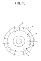
- FIGS. 1A and 1B illustrate the structure of a rotor of a conventional BLDC motor
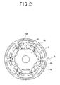
- FIG. 2 illustrates a magnetic circuit of a rotor and an armature 5 of a conventional BLDC motor.
- the rotor of the conventional BLDC motor has a structure in which a radially magnetized C-type permanent magnet 10 is attached to the outer circumferential face of an electric steel sheet ferromagnetic core portion 12 made of a ferromagnetic iron core or armature and a rotor shaft is inserted into a central portion of the ferromagnetic core portion 12.
- the C-type permanent magnet 10 is an anisotropic magnet that is magnetized radially around the center of the rotor shaft 14. In order to form a magnetic circuit 102 with a different pole of the rotor, the C-type permanent magnet 10 has to have a ferromagnetic material such as pure iron or an electric steel sheet core provided on its inner circumferential face.
- the magnetic circuit 102 through which flux flows is formed as illustrated in FIG. 2 .
- the pole shift of the armature 5 occurs in magnetic coupling of the formed magnetic circuit 102, the rotor rotates due to interaction torque of a rotating magnetic field.
- vibration caused by unbalance among magnetic flux densities of an air gap 105, a slot portion 15 of the armature 5, and a gap portion 16 of the permanent magnetic 10 of the rotor and magnetizing vibration caused by pole shift of the armature 5 are transferred to the ferromagnetic core portion 12 and a rotor shaft 14 through the permanent magnetic 10.
- Such vibration is directly transferred up to a load side through the rotor shaft 14, thereby amplifying mechanical vibration noise or causing resonance noise during the motor driving and increasing stress in a bearing while aggravating bearing noise, thus reducing the expected life span of a motor.
- a sound-absorbing resin portion 13 such as rubber or silicon resin is inserted between the ferromagnetic core portion 12 and the rotor shaft 14, thereby blocking noise and vibration transferred through the permanent magnetic 10 and the ferromagnetic core portion 12, as illustrated in FIG. 1B .
- the use of the magnetic core portion 12 cannot greatly reduce the weight of the rotor and the magnetic core portion 12 still acts as a medium through which cogging torque ripple, noise, or vibration generated in the rotor is transferred.
- the use of the sound-absorbing resin portion 13 around the rotor shaft 14 for blocking vibration has a limitation in blocking noise and vibration.
- a high-strength adhesive has to be used and the weight balance of the rotor may be broken during adhesion between at least two pieces divided from the permanence magnet 10.
- the conventional BLDC motor has to use an electric steel sheet core so as to maintain the maximum magnetic flux density of the permanent magnet rotor and to minimize a loss of a rotating electric field.
- cogging torque vibration due to interaction with an armature core and electromagnetic vibration noise of the rotating magnetic field are unavoidably transferred to a load side through the motor rotary shaft.
- Document JP 2001 112 203 shows a rotor of a brushless direct current motor, comprising:
- the present invention has been made in view of the above-mentioned problems occurring in the prior art, and it is an object of the present invention to provide a rotor of a BLDC motor, in which a permanent magnet of the rotor is formed integrally in a ring shape as one piece and has a magnetic circuit therein, thereby removing a need for a ferromagnetic for a separate magnetic circuit through which the magnetic flux of the permanent magnet can pass.
- a rotor of a brushless direct current (BLDC) motor according to claim 1.
- FIGS. 1A and 1B illustrate the structure of a rotor of a conventional BLDC motor
- FIG. 2 illustrates a magnetic circuit of the rotor and an armature of the conventional BLCD motor
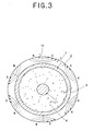
- FIG. 3 illustrates the structure of a rotor of a BLDC motor according to the present invention
- FIG. 4 illustrates a magnetic circuit of the rotor and an armature of the BLCD motor according to the present invention
- FIG. 5 is a cross-sectional view showing the rotor of the BLDC motor according to the present invention.
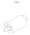
- FIG. 6 is a perspective view showing the rotor of the BLDC motor according to the present invention.
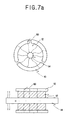
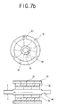
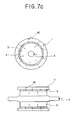
- FIGS. 7A through 7C are views showing comparison between a conventional technique and the present invention in order to explain the effects of the present invention.
- FIG. 3 illustrates the structure of a rotor of a BLDC motor according to the present invention.
- the rotor includes a cylindrical permanent magnet 1 and a cylindrical high-strength core portion 2 made of aluminum having a very low thermal expansion coefficient, alloy, or high-strength engineering plastic, which is adhered to the inner circumferential portion of the permanent magnet 1.
- the thickness of the high-strength core portion 2 is 40 - 100% of that of the permanent magnet 1.
- the cylindrical high-strength core portion 2 is inserted and adhered to the inner circumferential portion of the polar anisotropic permanent magnet 1, a sound-absorbing resin portion 3 made of rubber or sound-absorbing resin such as silicon resin is inserted and adhered to the inner circumferential portion of the high-strength core portion 2 to a thickness of two times that of the high-strength core portion 2, and a rotor shaft 4 is inserted into the center of the sound-absorbing resin portion 3.
- a high-strength material having superior heat-resisting property and a low thermal expansion coefficient is used, so as to prevent the cylindrical permanent magnet 1 from being damaged by the thermal expansion of the high-strength core portion 2 or the thermal expansion of the sound-absorbing resin portion 3.
- the permanent magnet 1 used for the rotor according to the present invention is a cylindrical polar permanent magnet formed as one piece.
- the effects of the present invention cannot be achieved by undirectedly magnetized isotropic cylindrical permanent magnets or radially magnetized anisotropic permanent magnets such as C-type permanent magnets, which have been used in common.
- the permanent magnet 1 used in the present invention has to be a polar anisotropic permanent magnet, through which a magnetized magnetic path runs, in order to complete the present invention.
- FIG. 4 illustrates a magnetic circuit 101 of the rotor and an armature of the BLCD motor according to the present invention.
- the rotor according to the present invention includes the magnetic circuit 101 in which a flux flow 11 is formed within the cylindrical permanent magnet 1 as illustrated in FIG. 4 .
- FIG. 5 is a cross-sectional view showing the rotor of the BLDC motor according to the present invention
- FIG. 6 is a perspective view showing the rotor of the BLDC motor according to the present invention.
- the rotor according to the present invention is completed by assembling the cylindrical polar anisotropic permanent magnet 1, the cylindrical high-strength core portion 2 in the inner circumferential portion of the permanent magnet 1, the sound-absorbing resin portion 3 in the inner circumferential portion of the high-strength core portion 2, and the rotor shaft 4 in the center of the sound-absorbing resin portion 3.
- FIGS. 7A through 7C are views showing comparison between a conventional technique and the present invention in order to explain the effects of the present invention.
- the amount of vibration transferred to the rotor shaft 14 through a conventional permanent magnet rotor as indicated by 60 of FIG. 7A or 61 of FIG. 7B is very large.
- the rotor according to the present invention uses the cylindrical polar anisotropic permanent magnet 1 formed as one piece, and a non-magnetic metal or high-strength plastic layer is primarily formed and a sound-absorbing resin or sound-absorbing material layer is secondarily formed in the inner circumferential portion of the rotor, thereby greatly reducing the weight of the BLDC motor.
- the rotor according to the present invention has the magnetic field 101 in which the flux flow 11 is formed inside the cylindrical permanent magnet 1, without a need to form the path of the magnetic circuit 101 in the permanent magnet 1 using a separate ferromagnetic.
- the high-strength core portion 2 made of a non-magnetic material or plastic that is light and has superior vibration/noise blocking property and the sound-absorbing resin portion 3 made of sound-absorbing plastic resin or other sound-absorbing materials can be used sufficiently in an inner circumferential space of the polar anisotropic permanent magnet 1, and noise and vibration generated in the air gap 105 between the armature 5 and the permanent magnet 1 can be prevented from being transferred to the rotor shaft 14.
- the rotor according to the present invention uses the cylindrical polar anisotropic permanent magnet, and a non-magnetic metal or high-strength plastic layer is primarily formed and a sound-absorbing resin or sound-absorbing material layer is secondarily formed in the inner circumferential portion of the rotor, thereby greatly reducing the weight of the BLDC motor.
Landscapes
- Engineering & Computer Science (AREA)
- Power Engineering (AREA)
- Permanent Field Magnets Of Synchronous Machinery (AREA)
- Iron Core Of Rotating Electric Machines (AREA)
Claims (1)
- Rotor eines bürstenlosen Gleichstrom-(BLDC)-Motors, umfassend:einen zylindrischen polar anisotropen Permanentmagneten (1) zum Erlauben, dass ein magnetischer Pfad dadurch hindurch läuft;einen hochfesten Kernabschnitt (2), welcher auf der inneren Seite des polar anisotropen Permanentmagneten (1) montiert ist; undeinen schallabsorbierenden Harzabschnitt (3), welcher direkt auf einer Welle (4) auf der inneren Seite des hochfesten Kernabschnitts (2) montiert ist, wobeider schallabsorbierende Harzabschnitt (3) eine Dicke eines Zweifachen von derjenigen des hochfesten Kernabschnitts (2) aufweist,wobei die Dicke des hochfesten Kernabschnitts (2) 40 - 100 % von derjenigen des polar anisotropen Permanentmagneten (1) ist, undwobei der hochfeste Kernabschnitt (2) gebildet ist aus irgendeinem von einem nicht-magnetischem Metall, Aluminium, welches einen niedrigen thermischen Ausdehnungskoeffizienten aufweist, einer Legierung oder einem hochfesten Maschinenbaukunststoff.
Priority Applications (3)
| Application Number | Priority Date | Filing Date | Title |
|---|---|---|---|
| EP07114432A EP2026449B1 (de) | 2007-08-16 | 2007-08-16 | Rotor für einen bürstenlosen Gleichstrommotor |
| ES07114432T ES2377665T3 (es) | 2007-08-16 | 2007-08-16 | Rotor de motor de corriente continua sin escobillas |
| EP08160618A EP2034589A3 (de) | 2007-08-16 | 2008-07-17 | Rotor für einen bürstenlosen Motor |
Applications Claiming Priority (1)
| Application Number | Priority Date | Filing Date | Title |
|---|---|---|---|
| EP07114432A EP2026449B1 (de) | 2007-08-16 | 2007-08-16 | Rotor für einen bürstenlosen Gleichstrommotor |
Publications (2)
| Publication Number | Publication Date |
|---|---|
| EP2026449A1 EP2026449A1 (de) | 2009-02-18 |
| EP2026449B1 true EP2026449B1 (de) | 2012-01-11 |
Family
ID=38835056
Family Applications (1)
| Application Number | Title | Priority Date | Filing Date |
|---|---|---|---|
| EP07114432A Not-in-force EP2026449B1 (de) | 2007-08-16 | 2007-08-16 | Rotor für einen bürstenlosen Gleichstrommotor |
Country Status (2)
| Country | Link |
|---|---|
| EP (1) | EP2026449B1 (de) |
| ES (1) | ES2377665T3 (de) |
Families Citing this family (2)
| Publication number | Priority date | Publication date | Assignee | Title |
|---|---|---|---|---|
| DE102017214555B4 (de) * | 2017-08-21 | 2019-10-24 | Continental Automotive Gmbh | Rotor und elektrische Maschine |
| JP7255214B2 (ja) * | 2019-02-05 | 2023-04-11 | 株式会社デンソー | 回転電機 |
Citations (1)
| Publication number | Priority date | Publication date | Assignee | Title |
|---|---|---|---|---|
| US5704111A (en) * | 1995-05-24 | 1998-01-06 | General Electric Company | Method for making a rotor for an electric motor |
Family Cites Families (7)
| Publication number | Priority date | Publication date | Assignee | Title |
|---|---|---|---|---|
| AT376849B (de) * | 1982-09-15 | 1985-01-10 | Philips Nv | Elektromotor |
| JPS6096961U (ja) * | 1983-12-08 | 1985-07-02 | 株式会社三協精機製作所 | 小型モ−タ用のロ−タ |
| JPH0638414A (ja) * | 1992-07-14 | 1994-02-10 | Daido Steel Co Ltd | リング状磁石をそなえたロータ |
| US5306123A (en) * | 1993-04-08 | 1994-04-26 | General Electric Company | Noise isolating rotor for air handler motor |
| JP2001112203A (ja) * | 1999-10-05 | 2001-04-20 | Hitachi Ltd | 回転電機 |
| JP2001314050A (ja) * | 2000-04-27 | 2001-11-09 | Sony Corp | Acサーボ・モータ |
| TW200518122A (en) * | 2003-07-22 | 2005-06-01 | Aichi Steel Corp | Thin hybrid magnetization type ring magnet, yoke-equipped thin hybrid magnetization type ring magnet, and brushless motor |
-
2007
- 2007-08-16 EP EP07114432A patent/EP2026449B1/de not_active Not-in-force
- 2007-08-16 ES ES07114432T patent/ES2377665T3/es active Active
Patent Citations (1)
| Publication number | Priority date | Publication date | Assignee | Title |
|---|---|---|---|---|
| US5704111A (en) * | 1995-05-24 | 1998-01-06 | General Electric Company | Method for making a rotor for an electric motor |
Also Published As
| Publication number | Publication date |
|---|---|
| ES2377665T3 (es) | 2012-03-29 |
| EP2026449A1 (de) | 2009-02-18 |
Similar Documents
| Publication | Publication Date | Title |
|---|---|---|
| US8456043B2 (en) | Rotor of brushless direct current motor having sound absorbing resin portion | |
| JP6161793B2 (ja) | 永久磁石式回転電機及びその製造方法 | |
| US6967420B2 (en) | Electrical machine having a rotor specially adapted to high speeds | |
| JP4608967B2 (ja) | ディスク型回転電機のロータ構造およびロータ製造方法 | |
| US8546990B2 (en) | Permanent magnet synchronous rotating electric machine and rotor core | |
| CN104662777B (zh) | 永磁体埋入型电动机 | |
| US9071118B2 (en) | Axial motor | |
| CN100426627C (zh) | 永磁式电动机 | |
| CN103780038B (zh) | 永磁旋转电机 | |
| JP4720982B2 (ja) | アキシャルエアギャップ型電動機 | |
| JP2006174554A (ja) | アキシャルギャップ型回転電機のロータ構造 | |
| US20110163618A1 (en) | Rotating Electrical Machine | |
| US7777391B2 (en) | Armature, motor and compressor and methods of manufacturing the same | |
| JP4580683B2 (ja) | 永久磁石式リラクタンス型回転電機 | |
| JP2007068318A (ja) | 磁石埋込型モータ | |
| CN101378216B (zh) | 无刷直流电机的转子 | |
| CA2597804C (en) | Rotor of brushless direct-current motor | |
| JP5904188B2 (ja) | マルチギャップ型回転電機 | |
| EP2026449A1 (de) | Rotor für einen bürstenlosen Gleichstrommotor | |
| JP2007300796A (ja) | 永久磁石形電動機の回転子 | |
| US20090295248A1 (en) | Electric motor | |
| JP2000069717A (ja) | 電動機 | |
| CN112821616B (zh) | 一种转子冲片及具有其的转子、电机和压缩机 | |
| JP2013126267A (ja) | 回転電気機械および圧縮機 | |
| KR100904910B1 (ko) | 무정류자 모터의 회전자 |
Legal Events
| Date | Code | Title | Description |
|---|---|---|---|
| PUAI | Public reference made under article 153(3) epc to a published international application that has entered the european phase |
Free format text: ORIGINAL CODE: 0009012 |
|
| AK | Designated contracting states |
Kind code of ref document: A1 Designated state(s): AT BE BG CH CY CZ DE DK EE ES FI FR GB GR HU IE IS IT LI LT LU LV MC MT NL PL PT RO SE SI SK TR |
|
| AX | Request for extension of the european patent |
Extension state: AL BA HR MK RS |
|
| 17P | Request for examination filed |
Effective date: 20090326 |
|
| 17Q | First examination report despatched |
Effective date: 20090421 |
|
| AKX | Designation fees paid |
Designated state(s): DE ES FR GB IT |
|
| GRAP | Despatch of communication of intention to grant a patent |
Free format text: ORIGINAL CODE: EPIDOSNIGR1 |
|
| GRAS | Grant fee paid |
Free format text: ORIGINAL CODE: EPIDOSNIGR3 |
|
| GRAA | (expected) grant |
Free format text: ORIGINAL CODE: 0009210 |
|
| AK | Designated contracting states |
Kind code of ref document: B1 Designated state(s): DE ES FR GB IT |
|
| REG | Reference to a national code |
Ref country code: GB Ref legal event code: FG4D |
|
| REG | Reference to a national code |
Ref country code: DE Ref legal event code: R096 Ref document number: 602007019937 Country of ref document: DE Effective date: 20120315 |
|
| REG | Reference to a national code |
Ref country code: ES Ref legal event code: FG2A Ref document number: 2377665 Country of ref document: ES Kind code of ref document: T3 Effective date: 20120329 |
|
| PLBE | No opposition filed within time limit |
Free format text: ORIGINAL CODE: 0009261 |
|
| STAA | Information on the status of an ep patent application or granted ep patent |
Free format text: STATUS: NO OPPOSITION FILED WITHIN TIME LIMIT |
|
| 26N | No opposition filed |
Effective date: 20121012 |
|
| REG | Reference to a national code |
Ref country code: DE Ref legal event code: R097 Ref document number: 602007019937 Country of ref document: DE Effective date: 20121012 |
|
| PGFP | Annual fee paid to national office [announced via postgrant information from national office to epo] |
Ref country code: ES Payment date: 20130828 Year of fee payment: 7 |
|
| PGFP | Annual fee paid to national office [announced via postgrant information from national office to epo] |
Ref country code: FR Payment date: 20130820 Year of fee payment: 7 Ref country code: GB Payment date: 20130823 Year of fee payment: 7 |
|
| PGFP | Annual fee paid to national office [announced via postgrant information from national office to epo] |
Ref country code: IT Payment date: 20130823 Year of fee payment: 7 |
|
| PGFP | Annual fee paid to national office [announced via postgrant information from national office to epo] |
Ref country code: DE Payment date: 20131029 Year of fee payment: 7 |
|
| REG | Reference to a national code |
Ref country code: DE Ref legal event code: R119 Ref document number: 602007019937 Country of ref document: DE |
|
| GBPC | Gb: european patent ceased through non-payment of renewal fee |
Effective date: 20140816 |
|
| PG25 | Lapsed in a contracting state [announced via postgrant information from national office to epo] |
Ref country code: IT Free format text: LAPSE BECAUSE OF NON-PAYMENT OF DUE FEES Effective date: 20140816 |
|
| REG | Reference to a national code |
Ref country code: FR Ref legal event code: ST Effective date: 20150430 |
|
| REG | Reference to a national code |
Ref country code: DE Ref legal event code: R119 Ref document number: 602007019937 Country of ref document: DE Effective date: 20150303 |
|
| PG25 | Lapsed in a contracting state [announced via postgrant information from national office to epo] |
Ref country code: DE Free format text: LAPSE BECAUSE OF NON-PAYMENT OF DUE FEES Effective date: 20150303 Ref country code: GB Free format text: LAPSE BECAUSE OF NON-PAYMENT OF DUE FEES Effective date: 20140816 |
|
| PG25 | Lapsed in a contracting state [announced via postgrant information from national office to epo] |
Ref country code: FR Free format text: LAPSE BECAUSE OF NON-PAYMENT OF DUE FEES Effective date: 20140901 |
|
| REG | Reference to a national code |
Ref country code: ES Ref legal event code: FD2A Effective date: 20150925 |
|
| PG25 | Lapsed in a contracting state [announced via postgrant information from national office to epo] |
Ref country code: ES Free format text: LAPSE BECAUSE OF NON-PAYMENT OF DUE FEES Effective date: 20140817 |