EP2027585B1 - Système de transfert de combustible - Google Patents
Système de transfert de combustible Download PDFInfo
- Publication number
- EP2027585B1 EP2027585B1 EP06850797.9A EP06850797A EP2027585B1 EP 2027585 B1 EP2027585 B1 EP 2027585B1 EP 06850797 A EP06850797 A EP 06850797A EP 2027585 B1 EP2027585 B1 EP 2027585B1
- Authority
- EP
- European Patent Office
- Prior art keywords
- carriage
- room
- boom
- container
- cover
- Prior art date
- Legal status (The legal status is an assumption and is not a legal conclusion. Google has not performed a legal analysis and makes no representation as to the accuracy of the status listed.)
- Not-in-force
Links
Images


Classifications
-
- G—PHYSICS
- G21—NUCLEAR PHYSICS; NUCLEAR ENGINEERING
- G21C—NUCLEAR REACTORS
- G21C19/00—Arrangements for treating, for handling, or for facilitating the handling of, fuel or other materials which are used within the reactor, e.g. within its pressure vessel
- G21C19/18—Apparatus for bringing fuel elements to the reactor charge area, e.g. from a storage place
-
- Y—GENERAL TAGGING OF NEW TECHNOLOGICAL DEVELOPMENTS; GENERAL TAGGING OF CROSS-SECTIONAL TECHNOLOGIES SPANNING OVER SEVERAL SECTIONS OF THE IPC; TECHNICAL SUBJECTS COVERED BY FORMER USPC CROSS-REFERENCE ART COLLECTIONS [XRACs] AND DIGESTS
- Y02—TECHNOLOGIES OR APPLICATIONS FOR MITIGATION OR ADAPTATION AGAINST CLIMATE CHANGE
- Y02E—REDUCTION OF GREENHOUSE GAS [GHG] EMISSIONS, RELATED TO ENERGY GENERATION, TRANSMISSION OR DISTRIBUTION
- Y02E30/00—Energy generation of nuclear origin
- Y02E30/30—Nuclear fission reactors
Definitions
- the present invention relates to a fuel transfer system for use in the reactor.
- Fuel transfer systems currently used in pressurized water reactors (PWR) and other reactors are inconvenient to repair and the repair process is time-consuming.
- some systems use air cylinders to up-end and down-end a fuel transfer container. Holes may develop in associated air hoses that disable the system or cause the system to operate unreliably.
- downtime of the fuel transfer system to perform maintenance on the system components is high and often occurs during the critical path of the system cycle.
- Another disadvantage is the number of components in current fuel transfer systems that need to interface to move a fuel transfer car to and from the reactor building.
- the invention provides a fuel transfer system according to claim 1.
- a fuel transfer system 10 is used for transferring fuel bundles between a reactor building 14 (i.e., a holding room) of a pressurized water reactor (PWR) facility, or other nuclear reactor facility, and a containment building 18 (i.e., a containment side) of the facility.
- the fuel transfer system 10 includes a boom assembly 22 ( Figs. 5A , 5B , and 6 ) that telescopes from the reactor building 14, through a canal 26 in a containment wall 30 separating the reactor building 14 and the containment building 18, and into the containment building 18.
- a fuel transfer carriage 34 may travel on a track system 38 to the containment building 18 from the reactor building 14. Both the boom assembly 22 and the carriage 34 are deployed using a wire rope rewind hoisting system 42, or other hoisting system or mechanical means.
- the carriage 34 is capable of down-ending ( Figs. 1B and 3 ) and up-ending ( Figs. 2 and 4 ) a fuel bundle container 46.
- the hoisting system 42 moves the carriage 38 between the two buildings 14, 18, extends and retracts the boom assembly 22, and up-ends and down-ends the container 46.
- the fuel transfer system 10 starts at a home position with the carriage 34 in the reactor building 14 and the container 46 in a down-ended position, as shown in Figs. 1A and 1B .
- the container 46 is rotated to an up-ended position and a fuel bundle (not shown) is deposited in the container 46.
- the fuel bundle may be picked up and deposited into the container 46 by a pick crane (not shown).
- the container 46 is then rotated to the down-ended position and the carriage 34 is moved to an unloading position in the containment building 18, as shown in Fig. 3 .
- Fig. 4 once the carriage 34 comes to a stop in the containment building 18, the container 46 is rotated to the up-ended position.
- a pick crane (not shown) picks the fuel bundle from the container 46 and deposits the bundle in a spent fuel pool (not shown).
- a technician may operate a controller, such as a programmable logic controller (PLC), a contactor controller, a digital controller, an adjustable frequency controller, or an infinitely variable controller (e.g., a Static SteplessTM controller provided by P&H Mining Equipment of Milwaukee, WI), to control operation of the fuel transfer system 10, including the hoisting system 42.
- a controller such as a programmable logic controller (PLC), a contactor controller, a digital controller, an adjustable frequency controller, or an infinitely variable controller (e.g., a Static SteplessTM controller provided by P&H Mining Equipment of Milwaukee, WI)
- PLC programmable logic controller
- contactor controller e.g., a contactor controller, a digital controller, an adjustable frequency controller, or an infinitely variable controller (e.g., a Static SteplessTM controller provided by P&H Mining Equipment of Milwaukee, WI)
- an infinitely variable controller e.g., a Static SteplessTM controller provided by P&H Mining Equipment of Milwaukee, WI
- the fuel transfer system 10 includes moving parts incorporated into a single apparatus that is capable of being serviced during off or outage time. All of the moving parts of the fuel transfer system 10 are located within the reactor building 14 of the facility, or movable to the reactor building 14. Therefore, maintenance downtimes are decreased and access to the system 10 during outage time is possible.
- the fuel transfer system 10 (except the hoists) is under water. However, it should be readily apparent to those of skill in the art that other components of the system may be positioned above water.
- the fuel transfer system 10 includes three track assemblies that are interconnected to form the track system 38, or path, that passes through the containment wall 30 and between the reactor building 14 and the containment building 18.
- a holding room track assembly 50 ( Fig. 7A ) is positioned in the reactor building 14 of the facility
- a canal track assembly 54 ( Fig. 7B ) is positioned in the canal 26
- a containment track assembly 58 ( Fig. 7C ) is positioned in the containment building 18 the facility.
- the canal track assembly 54 passes through the containment wall 30 to connect the holding room track assembly 50 and the containment track assembly 58.
- the containment wall 30 defines the canal 26 where the canal track 54 assembly is located.
- Each track assembly 50, 54, 58 defines a rail 62 on which the carriage 34 travels.
- At least the holding room track assembly 50 and the canal track assembly 54 include an inner rail 66 for supporting the carriage 34.
- the fuel transfer system 10 includes the fuel transfer carriage 34 that travels upon the rail 62 of the track assemblies 50, 54, 58 and moves between the reactor building 14 and the containment building 18 through the canal 26.
- the carriage 34 includes upper rollers 70 for riding on the rails 62, and lower rollers 74 for riding between the track rails 62 and the inner rails 66.
- the carriage 34 includes the container 46 pivotably coupled to the carriage 34 for storing fuel bundles during a transfer process.
- First container sheave 78 and second container sheave 80 are positioned inside opposite sides of the carriage 34 and on opposite pivot points of the container 46.
- the first and second container sheaves 78, 80 are part of the hoisting system 42 and are used to up-end and down-end the container 46 relative to the carriage 34, i.e., rotate the container 46 between the down-ended position ( Figs. 1B and 3 ) and the up-ended position ( Figs. 2 and 4 ).
- a cover 82 is pivotably coupled to a first end 86 of the carriage 34 for covering and closing an open end 90 of the container 46. When the cover 82 is pivoted to a closed position ( Fig. 8A ), the cover 82 holds the container 46 in the down-ended position and prevents rotation of the container 46 to the up-ended position. When the cover 82 is pivoted away from the container 46 to an open position ( Fig. 9 ), the container 46 is allowed to rotate to the up-ended position.
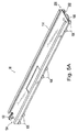
- the fuel transfer system 10 includes the boom assembly 22 ( Figs. 5A , 5B , and 6 ) for facilitating travel of the carriage 34 in conjunction with the hoisting system 42.
- the boom assembly 22 is received by the track assemblies 50, 54, 58 and travels along lower surfaces 94 of the track assemblies 50, 54, 58.
- the boom assembly 22 includes a main boom 98 ( Fig. 5A ) and a secondary boom 102 ( Fig. 5B ) received by the main boom 98 such that the secondary boom 102 telescopes (i.e., extends and retracts) relative to the main boom 98.
- the main boom 98 includes rollers 106 for traveling along the lower surfaces 94 of the track assemblies 50, 54, 58.
- the secondary boom 102 includes first rollers 110 proximate a first end 111 of the secondary boom 102 for traveling along the lower surfaces 94, and second rollers 112 proximate a second end 113 of the secondary boom 102 for traveling along rails 114 of the main boom 98.
- the main boom 98 travels between the reactor building 14 and the canal 26.
- the secondary boom 102 extends and retracts relative to the main boom 98, such that the secondary boom 102 travels between the reactor building 14, the canal 26, and the containment building 18.
- the hoisting system 42 moves the carriage 34 back and forth along the track assemblies 50, 54, 58 between the reactor building 14 and the containment building 18, up-ends and down-ends the container 46, and extends and retracts the boom assembly 22. Therefore, a single system is used to provide all three movements of the fuel transfer system 10.
- the hoisting system 42 includes a first carriage hoist 118( Fig. 1A and 10 ), a second carriage hoist 122 ( Fig. 1A and 11 ), a boom hoist 126 ( Fig. 1 A and 12 ), a plurality of sheaves ( Fig. 7A ) coupled to the holding room track assembly 50, the container sheaves 78, 80 ( Figs.
- the hoists 118, 122, 126 are supported by a pair of rails 134 ( Fig. 1A ) coupled to a wall of the reactor building 14, and are positioned above the holding room track assembly 50.
- the first and second carriage hoists 118, 122 pay-out, or release, and take-up a first carriage cable 138 ( Fig. 10 ) and a second carriage cable ( Fig. 11 ) respectively, both of which pass along a plurality of sheaves of the hoisting system 42.
- the first carriage cable 138 begins at a drum 146 of the first carriage hoist 118 and extends to the first carriage sheave 150 ( Figs. 7A and 10 ) mounted to a first end 154 of the holding room track assembly 50.
- the first carriage cable 138 then passes around the first carriage sheave 150 and extends to a bottom of the pulley 130 ( Figs. 5B and 10 ) on the secondary boom 102.
- the first carriage cable 138 passes around the pulley 130 and terminates on the first container sheave 78 ( Figs. 8B and 10 ).
- the first carriage cable 138 is used for extending the carriage 34 out of the reactor building 14 and rotating the container 46 to the up-ended position.
- the second carriage cable 142 begins at a drum 158 of the second carriage hoist 122.
- the second carriage cable 142 extends to a top of a second carriage sheave 162 ( Figs. 7A and 11 ) coupled to the first end 154 of the holding room track assembly 50, passes around the second carriage sheave 162, and extends to a top of the second container sheave 80 ( Figs. 8B and 11 ) mounted between the container 46 and the carriage 34.
- the second carriage cable 142 terminates at the second container sheave 80.
- the second carriage cable 142 is used for retracting the carriage 34 into the reactor building 14 and rotating the container 34 to the down-ended position.
- the boom hoist 126 pays-out and takes-up a boom cable 166 passing along a plurality of sheaves to extend and retract the boom assembly 22.
- the pulley 130 ( Fig. 5B ) on the secondary boom 102 moves relative to the carriage 34 to thereby facilitate movement of the carriage 34 along the track assemblies 50, 54, 58.
- the boom cable 166 begins at a smaller diameter drum 174 of the boom hoist 126 and extends to a first retract sheave 178 ( Figs. 7A and 12 ) coupled to the first end 154 of the holding room track assembly 50.
- the boom cable 166 then passes to a second retract sheave 182 ( Figs.
- the boom cable 166 extends to a securing point 186 ( Figs. 5B and 12 ) proximate the second end 113 of the secondary boom 102.
- the securing point 186 may include, for example, a bracket or bolt to hold the boom cable 166 stationary in relation to the secondary boom 102.
- the boom cable 166 extends from the securing point 186 to a first boom sheave 190 ( Figs. 5A and 12 ) coupled to a first end 194 of the main boom 98 (i.e., the end closest to the containment building 18).
- the boom cable 166 passes around the first boom sheave 190 and extends to a second boom sheave 198 ( Figs. 5A and 12 ) coupled to a bottom surface 202 of the main boom 98 at a second end 206 of the main boom 98.
- the boom cable 166 then extends to a track sheave 210 ( Figs. 7A and 12 ) coupled to a second end 214 of the holding room track assembly 50.
- the boom cable 166 After passing around the track sheave 210, the boom cable 166 passes through the first end 154 of the holding room track assembly 50 and extends to a first extend sheave 218 ( Figs. 7A and 12 ) mounted to the first end 154. The boom cable 166 then passes to a second extend sheave 222 ( Figs. 7A and 12 ) also mounted on the first end 154 of the holding room track assembly 50 and extends upward to terminate at a larger diameter drum 226 of the boom hoist 126.
- the boom cable 166 is formed from two separate cables, such that one cable extends between the small diameter drum 174 and the securing point 186 and a second cable extends between the securing point 186 and the large diameter drum 226. The separate cables would likewise engage all the respective sheaves between the termination points.
- a first distance between the track sheave 210 and the second boom sheave 198 is decreased or shortened (i.e., the distance between the two sheaves 198, 210 becomes smaller). Decreasing the first distance causes the main boom 98 to travel along the track system 38 from the holding room track assembly 50 to the canal track assembly 54. Likewise, at this time, a second distance between the first boom sheave 190 and the securing point 186 is also decreased, moving the secondary boom 102 relative to the main boom 98 from the canal track assembly 54 to the holding room track assembly 58.
- the first distance and the second distance are increased, thereby moving (i.e., retracting) the boom assembly 22 into the reactor building 14.
- the secondary boom 102 moves relative to the main boom 98 from the holding room track assembly 58 and is received by the main boom 98.
- the main boom 98 and the secondary boom 102 then travel from the canal track assembly 54 to the holding room track assembly 58.
- a constant total length of boom cable 166 is always released by the boom hoist 126.
- the amount of boom cable 160 engaging the sheaves and the boom assembly 22 is always the same.
- the ratio of a first boom cable length between the securing point 186 and the smaller diameter drum 174 and a second boom cable length between the securing point 186 and the larger diameter drum 226 varies during operation.
- the larger diameter drum 226 has a diameter approximately twice a diameter of the smaller diameter drum 174. Therefore, the track sheave 210 has a diameter approximately twice the diameter of the second boom sheave 198 to keep the total length of boom cable 166 released by the boom hoist 126 constant. It should be readily apparent to those skilled in the art to that a greater or smaller diameter ratio or fewer or more sheaves may be used to account for the different diameters of the drums 174, 226.
- the larger diameter drum 226 pays-out the boom cable 166 while the smaller diameter drum 174 takes-up the boom cable 166 to move the boom assembly 22 and the pulley 130 toward the containment building 18.
- the first carriage hoist 118 pays-out the first carriage cable 138 to the pulley 130 as the boom assembly 22 enters the containment building 18 and the pulley 130 approaches a first hard stop 230 ( Fig. 7C ) at a second end 234 of the containment track assembly 58.
- the first carriage hoist 118 then takes-up the first carriage cable 138 to extend the carriage 34 into the containment building 18 and up-end the container 46 once the carriage 34 reaches the second end 234 of the containment track assembly 58.
- the boom hoist 126 operates to extend the secondary boom 102 further into the containment building 18 and move the pulley 130 closer to the second end 234 of the containment track assembly 58.
- the second carriage hoist 122 takes-up the second carriage cable 142 to down-end the container 46 and return the carriage 34 to the reactor building 14.
- the boom hoist 126 then operates in reverse such that the larger diameter drum 226 takes-up the boom cable 166 while the smaller diameter drum 174 pays-out the boom cable 166 to retract the boom assembly 22 back into the reactor building 14.
- the cover 82 closes the open end 90 of the container 46 and maintains the container 46 in the down-ended position by keeping the container 46 from rotating to the up-ended position.
- the cover 82 includes a pair of outwardly extending fingers 238 and a spring 242 to bias the cover 82 to the closed position.
- the cover 82 is biased to the closed position ( Figs. 8A and 8B ) by the spring 242 and the first carriage hoist 118 is prevented from up-ending the container 46.
- stops 246 Fig.
- the container 46 remains down-ended and closed until the carriage 34 reaches the reactor building 14 and contacts a second hard stop 250 ( Fig. 7A ) positioned proximate the first end 154 of the holding room track assembly 50.
- the holding room track assembly 50 includes a pair of levers 254 coupled to the rail 62 of the holding room track assembly 50, one on each side.
- Each lever 254 includes an actuator 258 to move the lever 254 relative to the rail 62 (i.e., generally upwardly or downwardly).
- the actuators 258 extend the levers 254 to engage the fingers 238 of the cover 82 and release the cover 82 to the open position.
- the container 46 is allowed to rotate to the up-ended position.
- Retracting the actuators 258 disengages the levers 254 from the fingers 238, which causes the cover 82 to bias back to the closed position.
- the levers 254 may be manually actuated so that no electricity is required to pivot the cover 82.
- a first pin 262 ( Fig. 7A ) mounted to the holding room track assembly 50 locks the carriage 34 in the home position.
- the first end 86 of the carriage 34 includes a bracket 266 having an aperture 270 ( Fig. 8B ).
- the first pin 262 is received by the aperture 270 to hold the carriage 34 in the home position.
- the first pin 262 may be actuated by an electrical solenoid or manually displaced by a lever to slide downward into the aperture 270.
- the first pin 262 is positioned adjacent to the second hard stop 250 of the holding room track assembly 50.
- the latch pin 274 ( Fig. 7C ) extends from a bracket 282 coupled to the rail 62 at the second end 234 of the containment track assembly 58.
- the bracket 282 extends laterally inward from the rail 62 to the carriage travel path and the latch pin 274 extends upwardly from the bracket 282.
- the carriage 34 includes the latch 278 ( Figs. 8A and 8B ) and an L-shaped carriage bracket 286 ( Fig. 8A ), which are coupled to a second end 290 of the carriage 34.
- the latch 278 is rotatably coupled to the second end 290 of the carriage 34 and moves between an open position ( Fig. 8B ), whereby the carriage 34 is free to move along the track system 38, and a closed position ( Fig. 9 ), whereby the carriage 34 is locked in the unloading position.
- a lower portion of the carriage bracket 286 includes a bracket slot 294 that allows the latch 278 to pass therethrough.
- the carriage bracket 286 is movable between a first position ( Fig. 8A ), in which the carriage bracket 286 is held up by the container 46, and a second position ( Fig. 9 ), in which the carriage bracket 286 moves downward relative to the carriage 34 to prevent the latch 278 from entering the bracket slot 294.
- the carriage bracket 286 In the open position, the carriage bracket 286 is held up by the container 46, thereby positioning the bracket slot 294 in-line with the latch 278 to allow the latch 278 to pass through when rotating between the open position and the closed position.
- the carriage 34 As the carriage 34 travels along the containment track assembly 58, the carriage 34 is stopped in the containment building 18 by the first hard stop 230.
- the latch pin 274 enters a latch slot 298 on the latch 278 and causes the latch 278 to rotate clockwise through and past the bracket slot 294.
- the carriage bracket 286 drops downward to the second position such that the bracket slot 294 in unaligned with the latch 278.
- a spring (not shown) may be coupled between the carriage 34 and the carriage bracket 286 to bias the carriage bracket 286 downward.
- a stop pin 302 on the carriage bracket 286 prevents the carriage bracket 286 from sliding off the carriage 34.
- the carriage bracket 286 prevents the latch 278 from rotating counter-clockwise back to the open position, thereby restraining the carriage 34 from retracting towards the reactor building 14. Rotating the container 46 back to the down-ended position lifts the carriage bracket 286, thereby allowing the latch 278 to freely rotate out of the bracket slot 294.
- All of the moving parts of the fuel transfer system 10 are located in the reactor building 14 of the facility. Those parts that move into the containment building 18 may be moved to the reactor building 14 for maintenance. Therefore, planned maintenance and outage times are decreased because all of the moving parts may be positioned in the reactor building 14 without having to drain the containment building 18. Also, separate up-ending and down-ending machines are not required on both sides of the containment wall 30. The up-ending and down-ending of the container 46 relative to the carriage 34 is all done by the hoisting system 42 located in the reactor building 14. Therefore, the fuel transfer system 10 has fewer moving parts and systems to maintain.
Landscapes
- Physics & Mathematics (AREA)
- Engineering & Computer Science (AREA)
- Plasma & Fusion (AREA)
- General Engineering & Computer Science (AREA)
- High Energy & Nuclear Physics (AREA)
- Jib Cranes (AREA)
- Conveying And Assembling Of Building Elements In Situ (AREA)
Claims (9)
- Système de transfert de combustible servant à transporter du combustible usé d'une première chambre à une deuxième chambre, le système comportant :une première chambre (14) ;une deuxième chambre (18) séparée de la première chambre par une paroi de confinement (30) ayant un canal (26) entre les première et deuxième chambres ;un chariot (34) qui est agencé pour se déplacer entre la première chambre (14) et la deuxième chambre (18) au travers du canal ;dans lequel le chariot comprend un contenant (46) servant à contenir le combustible usé, le contenant étant monté de manière pivotante sur le chariot et étant rotatif entre une position à extrémité orientée vers le haut et une position à extrémité orientée vers le bas à la fois dans la première chambre et dans la deuxième chambre ;un ensemble bras (22) qui se déploie et se rétracte entre la première chambre et la deuxième chambre au travers du canal ; etun système de levage (42) comprenant des dispositifs de levage positionnés dans la première chambre, le système de levage comprenant au moins un câble de bras (166) connecté mutuellement avec l'ensemble bras et les dispositifs de levage de telle sorte que le déroulement et l'enroulement dudit au moins un câble de bras déploie et rétracte l'ensemble bras, et le système de levage comprenant des premier et deuxième câbles de chariot (138, 142) connectés mutuellement avec le chariot, et les dispositifs de levage de telle sorte que le déroulement et l'enroulement des premier et deuxième câbles de chariot déplacent le chariot entre la première chambre et la deuxième chambre ;dans lequel les premier et deuxième câbles de chariot (138, 142) sont connectés mutuellement avec des premier et deuxième réas de levage de contenant (78, 80) positionnés à l'intérieur de côtés opposés du chariot et sur des points de pivotement opposés du contenant, et les dispositifs de levage de telle sorte que le déroulement et l'enroulement des premier et deuxième câbles de chariot font tourner le contenant entre la position à extrémité orientée vers le haut et la position à extrémité orientée vers le bas à la fois dans la première chambre et dans la deuxième chambre, et toutes les pièces en mouvement du système de transfert de combustible peuvent être positionnées dans la première chambre à des fins de maintenance.
- Système selon la revendication 1, dans lequel le contenant comprend un couvercle (82), le couvercle étant en mesure de pivoter entre une position fermée pour empêcher la rotation du contenant et une position ouverte pour permettre la rotation du contenant.
- Système selon la revendication 2, dans lequel le contenant comprend un ressort (242) servant à solliciter le couvercle jusque sur la position fermée.
- Système selon la revendication 2 ou la revendication 3, et comportant par ailleurs au moins un actionneur (258) positionné dans la première chambre, dans lequel l'actionnement dudit au moins un actionneur met en prise une partie du couvercle à des fins de pivotement du couvercle jusque sur la position ouverte.
- Système selon la revendication 2, la revendication 3 ou la revendication 4, et comportant par ailleurs au moins une butée (246) positionnée dans la deuxième chambre, ladite au moins une butée étant configurée à des fins de mise en prise d'une partie du couvercle pour faire pivoter le couvercle jusque sur la position ouverte.
- Système selon l'une quelconque des revendications 1 à 5, dans lequel l'ensemble bras comprend un premier bras (98) et un deuxième bras (102), le deuxième bras étant reçu de manière coulissante par le premier bras de telle sorte que le deuxième bras (102) se télescope par rapport au premier bras (98).
- Système selon la revendication 6, dans lequel le deuxième bras comprend une poulie de chariot (130), la poulie de chariot étant positionnée à des fins de mise en prise du premier câble de chariot pour déplacer le chariot.
- Système selon l'une quelconque des revendications 1 à 7, et comportant par ailleurs au moins une goupille (262), dans lequel ladite au moins une goupille est positionnée dans la première chambre, et par ailleurs dans lequel le chariot comprend un support (266) configuré à des fins de mise en prise de ladite au moins une goupille pour retenir le chariot dans la première chambre.
- Système selon l'une quelconque des revendications 1 à 8, et comportant par ailleurs au moins une goupille, dans lequel ladite au moins une goupille (274) est positionnée dans la deuxième chambre, et par ailleurs dans lequel le chariot comprend un verrou (278) configuré à des fins de mise en prise de ladite au moins une goupille pour retenir le chariot dans la deuxième chambre.
Applications Claiming Priority (2)
| Application Number | Priority Date | Filing Date | Title |
|---|---|---|---|
| US80258406P | 2006-05-23 | 2006-05-23 | |
| PCT/US2006/061130 WO2007139590A2 (fr) | 2006-05-23 | 2006-11-21 | Système de transfert de combustible |
Publications (3)
| Publication Number | Publication Date |
|---|---|
| EP2027585A2 EP2027585A2 (fr) | 2009-02-25 |
| EP2027585A4 EP2027585A4 (fr) | 2012-04-04 |
| EP2027585B1 true EP2027585B1 (fr) | 2016-01-27 |
Family
ID=38779129
Family Applications (1)
| Application Number | Title | Priority Date | Filing Date |
|---|---|---|---|
| EP06850797.9A Not-in-force EP2027585B1 (fr) | 2006-05-23 | 2006-11-21 | Système de transfert de combustible |
Country Status (4)
| Country | Link |
|---|---|
| US (1) | US8526565B2 (fr) |
| EP (1) | EP2027585B1 (fr) |
| CA (1) | CA2652943C (fr) |
| WO (1) | WO2007139590A2 (fr) |
Families Citing this family (3)
| Publication number | Priority date | Publication date | Assignee | Title |
|---|---|---|---|---|
| US20140017049A1 (en) | 2012-07-13 | 2014-01-16 | Konecranes Plc | Cask transport assembly |
| US9786397B2 (en) | 2012-07-13 | 2017-10-10 | Konecranes Global Corporation | Cask transport assembly |
| RU2758628C1 (ru) * | 2020-09-04 | 2021-11-01 | Акционерное общество «Прорыв» | Система герметичной стыковки контейнера многоразового использования |
Family Cites Families (26)
| Publication number | Priority date | Publication date | Assignee | Title |
|---|---|---|---|---|
| US1589091A (en) * | 1918-11-04 | 1926-06-15 | Barber Greene Co | Portable conveyer |
| US1364883A (en) * | 1920-07-09 | 1921-01-11 | Mcdonald John Frank | Track-carrier |
| US1732207A (en) * | 1926-08-17 | 1929-10-15 | Chain Belt Co | Bucket and boom conveying and distributing mechanism |
| US3376988A (en) * | 1965-04-09 | 1968-04-09 | Klosk Lawrence | Materials handling assembly |
| US3637096A (en) * | 1969-02-27 | 1972-01-25 | Combustion Eng | Nuclear fuel transfer machine |
| US3629062A (en) * | 1969-05-12 | 1971-12-21 | Atomic Energy Commission | Transfer machine for nuclear reactor |
| US3765549A (en) * | 1971-10-21 | 1973-10-16 | Transfer Systems | Apparatus and method for loading nuclear fuel into a shipping cask without immersion in a pool |
| US3768668A (en) * | 1971-12-17 | 1973-10-30 | Combustion Eng | Fuel bundle and control element assembly handling mechanism |
| US4053067A (en) * | 1973-06-25 | 1977-10-11 | Westinghouse Electric Corporation | Fuel transfer system for a nuclear reactor |
| DE2408261A1 (de) * | 1974-02-21 | 1975-09-11 | Krupp Gmbh | Einrichtung zum umsetzen von brennelementen und regelstaeben in einem kernreaktor |
| US3940577A (en) * | 1974-06-12 | 1976-02-24 | Stock Equipment Company | Method and apparatus for controlling a transfer car from a remote station |
| US4069766A (en) * | 1975-11-28 | 1978-01-24 | Combustion Engineering, Inc. | Fuel transfer machine |
| US4113558A (en) * | 1976-12-07 | 1978-09-12 | Westinghouse Electric Corp. | Nuclear fuel handling grapple carriage with self-lubricating bearing |
| FR2520150A1 (fr) * | 1982-01-20 | 1983-07-22 | Alsthom Atlantique | Dispositif pour transferer horizontalement entre deux enceintes des elements combustibles nucleaires stockes en position verticale |
| US4572710A (en) * | 1982-06-14 | 1986-02-25 | General Signal Corporation | Method and apparatus for changing filters in nuclear power stations |
| US4717531A (en) * | 1983-09-23 | 1988-01-05 | Westinghouse Electric Corp. | Fuel transfer system upender using translation drive |
| US4649016A (en) * | 1985-10-09 | 1987-03-10 | Westinghouse Electric Corp. | Remotely operable fuel transfer system for nuclear reactor |
| US4761107A (en) * | 1986-06-19 | 1988-08-02 | Westinghouse Electric Corp. | Apparatus for transferring components to and from containers |
| US4749541A (en) * | 1986-12-05 | 1988-06-07 | Westinghouse Electric Corp. | Position sensing mechanism for a nuclear fuel transfer system |
| US4725398A (en) * | 1986-12-08 | 1988-02-16 | Nuclear Energy Services, Inc. | Cable reeving system |
| US4957405A (en) * | 1988-09-26 | 1990-09-18 | Consolidation Coal Company | Apparatus for mining |
| US5069863A (en) * | 1989-07-10 | 1991-12-03 | Westinghouse Electric Corp. | Dual winch nuclear fuel transfer system providing more reliable fuel transfer during refueling operations |
| US5291532A (en) * | 1992-02-14 | 1994-03-01 | General Electric Company | Fuel transfer system |
| US5687207A (en) * | 1996-04-02 | 1997-11-11 | Westinghouse Electric Corporation | Refueling machine |
| US6885718B1 (en) * | 1998-03-19 | 2005-04-26 | Framatome Anp Gmbh | Method and apparatus for transferring an article between fluid-filled vessels |
| US6404836B1 (en) * | 1999-02-12 | 2002-06-11 | Westinghouse Electric Company Llc | Removable spent fuel handling machine rail |
-
2006
- 2006-11-21 EP EP06850797.9A patent/EP2027585B1/fr not_active Not-in-force
- 2006-11-21 CA CA2652943A patent/CA2652943C/fr active Active
- 2006-11-21 WO PCT/US2006/061130 patent/WO2007139590A2/fr not_active Ceased
- 2006-11-21 US US12/301,882 patent/US8526565B2/en not_active Expired - Fee Related
Also Published As
| Publication number | Publication date |
|---|---|
| WO2007139590A2 (fr) | 2007-12-06 |
| EP2027585A2 (fr) | 2009-02-25 |
| CA2652943A1 (fr) | 2007-12-06 |
| US8526565B2 (en) | 2013-09-03 |
| US20100272224A1 (en) | 2010-10-28 |
| CA2652943C (fr) | 2016-06-07 |
| EP2027585A4 (fr) | 2012-04-04 |
| WO2007139590A3 (fr) | 2008-10-16 |
Similar Documents
| Publication | Publication Date | Title |
|---|---|---|
| US6254157B1 (en) | Load clamping and lifting apparatus | |
| US8714525B2 (en) | Portable manipulator for carrying out works on energized overhead electrical lines | |
| CN112758256B (zh) | 一种水下机器人布放回收止荡器、摆架和系统 | |
| US20170162284A1 (en) | Canister transfer system with independent traveling shielded bell | |
| US20080085177A1 (en) | Bottom block assembly with pivoting trunnion paddles | |
| US9732570B2 (en) | Apparatus for tripping oil pipe and system for automatic well workover | |
| CN208345053U (zh) | 一种电缆线盘自动缓存设备 | |
| CN110570963A (zh) | 一种滤芯抓取转运装置 | |
| EP2027585B1 (fr) | Système de transfert de combustible | |
| CN113724905B (zh) | 一种抓取设备 | |
| EP2380844B1 (fr) | Dispositif de levage | |
| US5795107A (en) | Rod handling method | |
| CN201942400U (zh) | 一种施工升降机与楼层防护门的联锁装置 | |
| US10128009B2 (en) | System for handling fuel elements | |
| JP7482898B2 (ja) | 沸騰水型原子炉のブレードガイド・交換ツール | |
| US10556784B2 (en) | Lifting system and method for lifting and/or lowering loads | |
| JP2796469B2 (ja) | 空間移動装置 | |
| US20180374591A1 (en) | System for transferring fuel elements in a nuclear power plant | |
| CN209837430U (zh) | 一种核电站建安可转动活动屋面 | |
| CN211336345U (zh) | 一种具有防脱绳结构的导缆器 | |
| CN108766606A (zh) | 核电厂可燃毒物组件与中子源组件倒换工具 | |
| CN121405000A (zh) | 一种软管自动提升装置 | |
| CA2766583C (fr) | Dispositif et methodes de manipulation de materiaux destines au retubage d'un reacteur nucleaire | |
| US6361674B1 (en) | Powered lift for ECP chamber | |
| JPH04319020A (ja) | 線材または細い鋼材用の束形成兼搬送系を有する設備 |
Legal Events
| Date | Code | Title | Description |
|---|---|---|---|
| PUAI | Public reference made under article 153(3) epc to a published international application that has entered the european phase |
Free format text: ORIGINAL CODE: 0009012 |
|
| AK | Designated contracting states |
Kind code of ref document: A2 Designated state(s): AT BE BG CH CY CZ DE DK EE ES FI FR GB GR HU IE IS IT LI LT LU LV MC NL PL PT RO SE SI SK TR |
|
| AX | Request for extension of the european patent |
Extension state: AL BA HR MK RS |
|
| 17P | Request for examination filed |
Effective date: 20090416 |
|
| RBV | Designated contracting states (corrected) |
Designated state(s): AT BE BG CH CY CZ DE DK EE ES FI FR GB GR HU IE IS IT LI LT LU LV MC NL PL PT RO SE SI SK TR |
|
| DAX | Request for extension of the european patent (deleted) | ||
| REG | Reference to a national code |
Ref country code: DE Ref legal event code: R079 Ref document number: 602006047853 Country of ref document: DE Free format text: PREVIOUS MAIN CLASS: G21C0019000000 Ipc: G21C0019180000 |
|
| A4 | Supplementary search report drawn up and despatched |
Effective date: 20120305 |
|
| RIC1 | Information provided on ipc code assigned before grant |
Ipc: G21C 19/18 20060101AFI20120228BHEP |
|
| 17Q | First examination report despatched |
Effective date: 20130705 |
|
| GRAP | Despatch of communication of intention to grant a patent |
Free format text: ORIGINAL CODE: EPIDOSNIGR1 |
|
| INTG | Intention to grant announced |
Effective date: 20150609 |
|
| GRAS | Grant fee paid |
Free format text: ORIGINAL CODE: EPIDOSNIGR3 |
|
| GRAA | (expected) grant |
Free format text: ORIGINAL CODE: 0009210 |
|
| AK | Designated contracting states |
Kind code of ref document: B1 Designated state(s): AT BE BG CH CY CZ DE DK EE ES FI FR GB GR HU IE IS IT LI LT LU LV MC NL PL PT RO SE SI SK TR |
|
| REG | Reference to a national code |
Ref country code: GB Ref legal event code: FG4D |
|
| REG | Reference to a national code |
Ref country code: CH Ref legal event code: EP |
|
| REG | Reference to a national code |
Ref country code: AT Ref legal event code: REF Ref document number: 773037 Country of ref document: AT Kind code of ref document: T Effective date: 20160215 |
|
| REG | Reference to a national code |
Ref country code: IE Ref legal event code: FG4D |
|
| REG | Reference to a national code |
Ref country code: DE Ref legal event code: R096 Ref document number: 602006047853 Country of ref document: DE |
|
| REG | Reference to a national code |
Ref country code: LT Ref legal event code: MG4D |
|
| REG | Reference to a national code |
Ref country code: NL Ref legal event code: MP Effective date: 20160127 |
|
| REG | Reference to a national code |
Ref country code: AT Ref legal event code: MK05 Ref document number: 773037 Country of ref document: AT Kind code of ref document: T Effective date: 20160127 |
|
| PG25 | Lapsed in a contracting state [announced via postgrant information from national office to epo] |
Ref country code: NL Free format text: LAPSE BECAUSE OF FAILURE TO SUBMIT A TRANSLATION OF THE DESCRIPTION OR TO PAY THE FEE WITHIN THE PRESCRIBED TIME-LIMIT Effective date: 20160127 |
|
| PG25 | Lapsed in a contracting state [announced via postgrant information from national office to epo] |
Ref country code: IT Free format text: LAPSE BECAUSE OF FAILURE TO SUBMIT A TRANSLATION OF THE DESCRIPTION OR TO PAY THE FEE WITHIN THE PRESCRIBED TIME-LIMIT Effective date: 20160127 Ref country code: ES Free format text: LAPSE BECAUSE OF FAILURE TO SUBMIT A TRANSLATION OF THE DESCRIPTION OR TO PAY THE FEE WITHIN THE PRESCRIBED TIME-LIMIT Effective date: 20160127 Ref country code: FI Free format text: LAPSE BECAUSE OF FAILURE TO SUBMIT A TRANSLATION OF THE DESCRIPTION OR TO PAY THE FEE WITHIN THE PRESCRIBED TIME-LIMIT Effective date: 20160127 Ref country code: GR Free format text: LAPSE BECAUSE OF FAILURE TO SUBMIT A TRANSLATION OF THE DESCRIPTION OR TO PAY THE FEE WITHIN THE PRESCRIBED TIME-LIMIT Effective date: 20160428 |
|
| PG25 | Lapsed in a contracting state [announced via postgrant information from national office to epo] |
Ref country code: PL Free format text: LAPSE BECAUSE OF FAILURE TO SUBMIT A TRANSLATION OF THE DESCRIPTION OR TO PAY THE FEE WITHIN THE PRESCRIBED TIME-LIMIT Effective date: 20160127 Ref country code: PT Free format text: LAPSE BECAUSE OF FAILURE TO SUBMIT A TRANSLATION OF THE DESCRIPTION OR TO PAY THE FEE WITHIN THE PRESCRIBED TIME-LIMIT Effective date: 20160527 Ref country code: LV Free format text: LAPSE BECAUSE OF FAILURE TO SUBMIT A TRANSLATION OF THE DESCRIPTION OR TO PAY THE FEE WITHIN THE PRESCRIBED TIME-LIMIT Effective date: 20160127 Ref country code: IS Free format text: LAPSE BECAUSE OF FAILURE TO SUBMIT A TRANSLATION OF THE DESCRIPTION OR TO PAY THE FEE WITHIN THE PRESCRIBED TIME-LIMIT Effective date: 20160527 Ref country code: AT Free format text: LAPSE BECAUSE OF FAILURE TO SUBMIT A TRANSLATION OF THE DESCRIPTION OR TO PAY THE FEE WITHIN THE PRESCRIBED TIME-LIMIT Effective date: 20160127 Ref country code: LT Free format text: LAPSE BECAUSE OF FAILURE TO SUBMIT A TRANSLATION OF THE DESCRIPTION OR TO PAY THE FEE WITHIN THE PRESCRIBED TIME-LIMIT Effective date: 20160127 Ref country code: SE Free format text: LAPSE BECAUSE OF FAILURE TO SUBMIT A TRANSLATION OF THE DESCRIPTION OR TO PAY THE FEE WITHIN THE PRESCRIBED TIME-LIMIT Effective date: 20160127 |
|
| REG | Reference to a national code |
Ref country code: DE Ref legal event code: R097 Ref document number: 602006047853 Country of ref document: DE |
|
| PG25 | Lapsed in a contracting state [announced via postgrant information from national office to epo] |
Ref country code: DK Free format text: LAPSE BECAUSE OF FAILURE TO SUBMIT A TRANSLATION OF THE DESCRIPTION OR TO PAY THE FEE WITHIN THE PRESCRIBED TIME-LIMIT Effective date: 20160127 Ref country code: EE Free format text: LAPSE BECAUSE OF FAILURE TO SUBMIT A TRANSLATION OF THE DESCRIPTION OR TO PAY THE FEE WITHIN THE PRESCRIBED TIME-LIMIT Effective date: 20160127 |
|
| REG | Reference to a national code |
Ref country code: FR Ref legal event code: PLFP Year of fee payment: 11 |
|
| PG25 | Lapsed in a contracting state [announced via postgrant information from national office to epo] |
Ref country code: CZ Free format text: LAPSE BECAUSE OF FAILURE TO SUBMIT A TRANSLATION OF THE DESCRIPTION OR TO PAY THE FEE WITHIN THE PRESCRIBED TIME-LIMIT Effective date: 20160127 Ref country code: RO Free format text: LAPSE BECAUSE OF FAILURE TO SUBMIT A TRANSLATION OF THE DESCRIPTION OR TO PAY THE FEE WITHIN THE PRESCRIBED TIME-LIMIT Effective date: 20160127 Ref country code: SK Free format text: LAPSE BECAUSE OF FAILURE TO SUBMIT A TRANSLATION OF THE DESCRIPTION OR TO PAY THE FEE WITHIN THE PRESCRIBED TIME-LIMIT Effective date: 20160127 |
|
| PLBE | No opposition filed within time limit |
Free format text: ORIGINAL CODE: 0009261 |
|
| STAA | Information on the status of an ep patent application or granted ep patent |
Free format text: STATUS: NO OPPOSITION FILED WITHIN TIME LIMIT |
|
| PG25 | Lapsed in a contracting state [announced via postgrant information from national office to epo] |
Ref country code: BE Free format text: LAPSE BECAUSE OF FAILURE TO SUBMIT A TRANSLATION OF THE DESCRIPTION OR TO PAY THE FEE WITHIN THE PRESCRIBED TIME-LIMIT Effective date: 20160127 |
|
| 26N | No opposition filed |
Effective date: 20161028 |
|
| PG25 | Lapsed in a contracting state [announced via postgrant information from national office to epo] |
Ref country code: SI Free format text: LAPSE BECAUSE OF FAILURE TO SUBMIT A TRANSLATION OF THE DESCRIPTION OR TO PAY THE FEE WITHIN THE PRESCRIBED TIME-LIMIT Effective date: 20160127 Ref country code: BG Free format text: LAPSE BECAUSE OF FAILURE TO SUBMIT A TRANSLATION OF THE DESCRIPTION OR TO PAY THE FEE WITHIN THE PRESCRIBED TIME-LIMIT Effective date: 20160427 |
|
| REG | Reference to a national code |
Ref country code: DE Ref legal event code: R119 Ref document number: 602006047853 Country of ref document: DE |
|
| REG | Reference to a national code |
Ref country code: CH Ref legal event code: PL |
|
| PG25 | Lapsed in a contracting state [announced via postgrant information from national office to epo] |
Ref country code: CH Free format text: LAPSE BECAUSE OF NON-PAYMENT OF DUE FEES Effective date: 20161130 Ref country code: LI Free format text: LAPSE BECAUSE OF NON-PAYMENT OF DUE FEES Effective date: 20161130 |
|
| REG | Reference to a national code |
Ref country code: IE Ref legal event code: MM4A |
|
| PG25 | Lapsed in a contracting state [announced via postgrant information from national office to epo] |
Ref country code: LU Free format text: LAPSE BECAUSE OF NON-PAYMENT OF DUE FEES Effective date: 20161130 |
|
| REG | Reference to a national code |
Ref country code: FR Ref legal event code: PLFP Year of fee payment: 12 |
|
| PG25 | Lapsed in a contracting state [announced via postgrant information from national office to epo] |
Ref country code: IE Free format text: LAPSE BECAUSE OF NON-PAYMENT OF DUE FEES Effective date: 20161121 Ref country code: DE Free format text: LAPSE BECAUSE OF NON-PAYMENT OF DUE FEES Effective date: 20170601 |
|
| PG25 | Lapsed in a contracting state [announced via postgrant information from national office to epo] |
Ref country code: HU Free format text: LAPSE BECAUSE OF FAILURE TO SUBMIT A TRANSLATION OF THE DESCRIPTION OR TO PAY THE FEE WITHIN THE PRESCRIBED TIME-LIMIT; INVALID AB INITIO Effective date: 20061121 Ref country code: CY Free format text: LAPSE BECAUSE OF FAILURE TO SUBMIT A TRANSLATION OF THE DESCRIPTION OR TO PAY THE FEE WITHIN THE PRESCRIBED TIME-LIMIT Effective date: 20160127 |
|
| PG25 | Lapsed in a contracting state [announced via postgrant information from national office to epo] |
Ref country code: MC Free format text: LAPSE BECAUSE OF FAILURE TO SUBMIT A TRANSLATION OF THE DESCRIPTION OR TO PAY THE FEE WITHIN THE PRESCRIBED TIME-LIMIT Effective date: 20160127 Ref country code: TR Free format text: LAPSE BECAUSE OF FAILURE TO SUBMIT A TRANSLATION OF THE DESCRIPTION OR TO PAY THE FEE WITHIN THE PRESCRIBED TIME-LIMIT Effective date: 20160127 |
|
| PGFP | Annual fee paid to national office [announced via postgrant information from national office to epo] |
Ref country code: GB Payment date: 20231123 Year of fee payment: 18 |
|
| PGFP | Annual fee paid to national office [announced via postgrant information from national office to epo] |
Ref country code: FR Payment date: 20231120 Year of fee payment: 18 |
|
| GBPC | Gb: european patent ceased through non-payment of renewal fee |
Effective date: 20241121 |
|
| PG25 | Lapsed in a contracting state [announced via postgrant information from national office to epo] |
Ref country code: GB Free format text: LAPSE BECAUSE OF NON-PAYMENT OF DUE FEES Effective date: 20241121 |
|
| PG25 | Lapsed in a contracting state [announced via postgrant information from national office to epo] |
Ref country code: FR Free format text: LAPSE BECAUSE OF NON-PAYMENT OF DUE FEES Effective date: 20241130 |