EP2027768B1 - Appareil de découpage - Google Patents
Appareil de découpage Download PDFInfo
- Publication number
- EP2027768B1 EP2027768B1 EP20070114792 EP07114792A EP2027768B1 EP 2027768 B1 EP2027768 B1 EP 2027768B1 EP 20070114792 EP20070114792 EP 20070114792 EP 07114792 A EP07114792 A EP 07114792A EP 2027768 B1 EP2027768 B1 EP 2027768B1
- Authority
- EP
- European Patent Office
- Prior art keywords
- cutting apparatus
- motor
- blade
- control means
- speed
- Prior art date
- Legal status (The legal status is an assumption and is not a legal conclusion. Google has not performed a legal analysis and makes no representation as to the accuracy of the status listed.)
- Active
Links
Images

Classifications
-
- A—HUMAN NECESSITIES
- A01—AGRICULTURE; FORESTRY; ANIMAL HUSBANDRY; HUNTING; TRAPPING; FISHING
- A01G—HORTICULTURE; CULTIVATION OF VEGETABLES, FLOWERS, RICE, FRUIT, VINES, HOPS OR SEAWEED; FORESTRY; WATERING
- A01G3/00—Cutting implements specially adapted for horticultural purposes; Delimbing standing trees
- A01G3/04—Apparatus for trimming hedges, e.g. hedge shears
- A01G3/047—Apparatus for trimming hedges, e.g. hedge shears portable
- A01G3/053—Apparatus for trimming hedges, e.g. hedge shears portable motor-driven
Definitions
- the present invention relates to cutting apparatus.
- it relates to control systems for vegetation cutters especially hedge cutters or trimmers.
- Hedgecutters comprise two elongate blades which reciprocate with respect to each other. Either one blade is fixed and the other caused to reciprocate or both blades caused to reciprocate in an equal and opposite manner.
- the blades are driven by means of a cam element driven by the output shaft of an electric motor or small engine.
- One such cutter is described in JP2005269972 , which hedge cutter also includes a switch allowing the user to reverse the direction of motion of one of the blades.
- Hedgecutters frequently suffer in use from a problem of blocked cutting blades when they encounter a twig or branch whose size or density exceeds the capacity of the blades or a wire causing the movable blade or blades to stall.
- the operator typically removes the power to the blades to remove the pressure of the moving blade on the branch and then attempts to remove the branch by pulling the branch. This can give rise to substantial safety considerations as the user places their fingers near to the blades. Similar problems are presented with other cutting tools.
- a cutting apparatus such as a hedgecutter or trimmer having at least one driven blade movable between two predefined points of maximum travel, the apparatus further comprising a prime mover, suitably an electric motor, adapted to cause movement of the said at least one movable blade between said points of maximum travel.
- the cutting apparatus is characterised in that it is further provided with a control means, suitably in the form of a control circuit, which causes a change of direction in the movement of the at least one movable blade at a point intermediate the points of maximum travel in response to an event sensed by the control means.
- the change of direction is achieved by a change in the direction of motor rotation.
- the event is an increase in cutting load.
- the control circuit includes a current sensing circuit such that, when the current drawn by the motor exceeds a predetermined level, the control circuit reverses the direction of rotation of the motor.
- the control circuit includes a speed sensor, adapted to sense when the speed of the driven blade falls below a predetermined level.
- the event is removal of power to the driven blade.
- the control circuit is adapted to cause rotation of the motor sequentially in a first direction upon a first application of electrical power to the motor and in a second direction upon a subsequent application of electrical power to the motor.
- control circuit is adapted to operate the motor in the reverse direction for a predetermined period whereupon the circuit then causes operation of the motor in the normal direction.
- the predetermined period is less than 1 second, more suitably less than half a second, even more suitably from 200 ms to 400 ms.
- the present invention develops the invention described in our earlier application by providing that the control means additionally applies a decreased operating speed to the at least one movable blade for a predefined period upon the or each change of direction in the movement of the at least one movable blade in response to the event sensed by the control means. Reducing the speed of the at least one movable blade has the effect of reducing impact forces on the mechanical components of the apparatus if the blocking condition remains.
- the present invention provides a cutting apparatus having at least one driven blade movable between two predefined points of maximum travel, the apparatus further comprising a prime mover adapted to cause movement of the said at least one movable blade between said points of maximum travel; characterised in that the cutting apparatus is further provided with a control means which causes a change of direction in the movement of the at least one movable blade at a point intermediate the points of maximum travel in response to an event sensed by the control means and further characterised in that the control means applies a reduced operating speed to the at least one movable blade for a predefined period upon the or each change of direction in the movement of the at least one movable blade in response to the event sensed by the control means.
- the prime mover is an electric motor. More preferably, the change of direction is achieved by a change in the direction of motor rotation.
- the speed of the blade is reduced to 30 to 90% of the normal operating speed during the predefined period; more preferably between 40 and 80%, most preferably 50 - 75%
- the predefined period is from 50 to 1000 milliseconds more preferably from 100 to 500 milliseconds.
- control means comprises a control circuit.
- the event is an increase in cutting load.
- the control circuit includes a current sensing circuit such that, when the current drawn by the motor exceeds a predetermined level, the control circuit reverses the direction of rotation of the motor.
- the control circuit includes a speed sensor, adapted to sense when the speed of the driven blade falls below a predetermined level.
- the event is removal of power to the driven blade.
- the control circuit is adapted to cause rotation of the motor sequentially in a first direction upon a first application of electrical power to the motor and in a second direction upon a subsequent application of electrical power to the motor.
- control circuit is adapted to operate the motor in the reverse direction for a predetermined period whereupon the circuit then causes operation of the motor in the normal direction.
- the predetermined period is less than 1 second, more suitably less than half a second, even more suitably from 200 ms to 400 ms.
- control means senses continued blocking as a further event and again changes the direction of movement of the at last one movable blade.
- the control means is adapted to limit the number of changes of direction permitted before power to the motor is removed completely. This may be achieved by the control circuit including a timer circuit, to limit the number of changes of direction within a specified period, such as 10 - 20 reversals within the period of up to 5 seconds or so.
- control circuit monitors the speed of the blade and removes power if the speed does not reach a prescribed level typically the normal operating speed within a specified number of reversals, typically 10 to 20. When the limit is reached, the control means disables output power completely from the prime mover unless the apparatus is restarted manually by the user by means of release and reapplication of the normal operating switches.
- the cutting tool is a portable tool. More preferably, the cutting tool is a vegetation cutter, most preferably a hedge cutter or hedge trimmer.
- the cutting tool comprises an electric motor powered by means of a rechargeable battery or cell.
- the battery is a lithium ion battery.
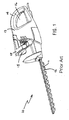
- a typical cutting apparatus in accordance with the present invention is in the form of a an electric hedgecutter 10 having a bottom blade 11 and upper blade 12 caused to reciprocate simultaneously and in an equal and opposite manner with respect to the housing and hence also to each other by means of an electric motor housed in a housing unit 13.
- the housing unit 13 includes two grips 14,15, each associated with a switch arrangement 16,17.
- This switching configuration provides a safety feature requiring both left and right hands of the operator to be in position and actuating their respective switches in order to supply an electric current to the motor. Accordingly, the blades cannot be put into an operating configuration unless both hands are away from the blades.
- the motor acts to reciprocate the moving blades 11, 12 in a conventional manner through suitable gearing as required.
- a hedgecutter in accordance with the present invention, it is possible to drive the reciprocating blade 11 in a reverse direction, compared with its normal cutting direction.
- the term 'reverse' is used in a relative sense rather than an absolute sense.
- a hedgecutter frequently suffers from jamming when it encounters a branch or twig whose diameter or density exceeds the capacity of the blades. This jamming or blocking is overcome by a hedgecutter in accordance with the present invention in one of two ways.
- the reciprocating blade is caused to reverse direction for a brief period, sufficient to release the jammed branch, before resuming its conventional direction automatically, without the operator releasing the switches.
- the reciprocating blade is caused to reverse its direction and maintain the reversed direction until such time as a further jammed situation is detected, whereupon the direction is reversed again, to the original direction, and so on automatically, without the operator releasing the switches.
- the blade upon encountering a jammed or stalled situation, the blade is caused to oscillate back and forth, thereby cutting the branch from both sides and achieving a cut which would not otherwise have been possible with the hedgecutter. Accordingly, the present invention not only provides a solution to the problem of stalled blades due to jamming but also extends the cutting capability of the cutting tool.
- the brushes are mechanically moved, suitably by means of an electromechanical switching arrangement, thereby replicating the commuter/brush shift for the alternative direction of running.
- the vegetation cutter is battery-powered, more preferably by means of a Li-ion battery unit.
- Devices using Li-ion batteries typically include an undervoltage protection circuit. This can be adapted to include the control circuit for the reverse drive operation of the present invention, for example, change of motor direction can be readily accomplished by means of a MOSFET bridge. If a brushless DC motor is utilised, the commutation electronics can advantageously be programmed to reverse the motor direction.
- the blade reversal event is advantageously triggered by detection of an increase in or high values of cutting load.
- the control circuit includes a current sensing circuit for this purpose, adapted to initiate motor reverse when the current drawn by the motor exceeds a predetermined level. Typically, this would be the value at stall, although a value less than stall can be used such that the motor is not permitted to reach a stall condition. Accordingly, the battery charge is prolonged as it is not permitted to supply a full stall current, acting as further protection, in addition to the normal protection, to prevent abuse from overcurrent.
- blade reversal can be triggered on each occasion electrical power is applied to the motor.
- the motor is re-energised in a stall situation, the reciprocating blade(s) therefore reverses to clear the stall.
- the vegetation cutter may include gearing adapted to allow a lower ratio geared reverse from that of the forward direction. This acts to aid unblocking of the blades and is particularly suitable for embodiments in which the reversal of blade movement is only temporary.
- Figure 2 shows a graph schematically representing, by means of a thin line, the speed of rotation of an electric motor in a hedge cutter in accordance with our earlier application with respect to time from start-up (point A) through stall conditions B, C and D.
- start-up the speed of rotation gradually builds up to a working speed w.
- the blades encounter a branch which causes the blades to stall and the speed of the motor falls instantaneously to zero.
- the control means causes the motor to re-energise and rotate in a reverse direction, building up rotational speed from zero to a working speed of -w.
- the graph also indicates, by means of thick lines, impact energy levels upon components of the moving mechanical parts of the apparatus, such as reciprocating parts such as the blades, or rotating parts such as the motor rotor and gearing, caused by the sudden arresting of their motion in a stall or blocking condition.
- the impact energy is substantially constant, causing significant stress on the mechanical parts and risking failure of the apparatus.
- Figure 3 shows the same elements in respect of a cutting apparatus in accordance with the present invention.
- the speed of rotation of the motor is increased by the control circuit to an initial level of around one half of the normal working speed w and remains at that level for a predetermined period p from start up (point A). Thereafter it increases to the full working speed w.
- control of the blade speed is achieved by control of the motor supply voltage.
- direct electronic speed regulation can be used, especially with an electronically-commutated motor with speed control electronic circuitry.
- the apparatus encounters a stall condition at B and the impact stresses will be at the same level as before, since the apparatus was operating at full speed.
- the power to the motor is removed for a brief period t as before, before the motor is re-energised in the reversed direction and its speed of rotation controlled again to the initial level of around w/2 again taking a period p. If a stall condition still applies, the impact energy at this lower speed is greatly reduced, as shown by the thick lines.
- the delay time p is chosen such that, after a reversal following a stall condition, the blades will reach at least their point of maximum travel at the reduced speed level. Thus, if a blocking situation remains between the blades, it will be encountered by the movable blade at a reduced speed.
- period p is up to 1 second in duration, preferably between 100ms and 500ms, which period will not generally be noticed by a user of the apparatus.
- the impact energy is proportional to the square of the rotational speed and so a halving of the rotational speed equates to a lowering of the impact energy to just 25% of that shown in Figure 2 .
- this also means that relatively small reductions in blade speed can have a relatively large decrease in stresses.
- reductions of blade speed are preferably in the range of 10 to 70% (equating to 30 to 90% of normal speed), more preferably in the range of 20 to 60%.
- Speed reductions of 25 to 50% are particularly preferred in providing a good balance between maintaining adequate power and reducing stresses.
- control means increases the power of the motor back to full normal working speed w. If a further blocking condition is encountered (as shown), the motor is again reversed.
Landscapes
- Life Sciences & Earth Sciences (AREA)
- Biodiversity & Conservation Biology (AREA)
- Ecology (AREA)
- Forests & Forestry (AREA)
- Environmental Sciences (AREA)
- Harvester Elements (AREA)
Claims (12)
- Appareil de coupe (10) comprenant au moins une lame (11, 12) déplaçable entre deux points prédéfinis de course maximale, l'appareil (10) comprenant en outre un moteur d'entraînement prévu pour entraîner ladite au moins une lame déplaçable (11, 12) entre lesdits points de course maximale à une vitesse de fonctionnement normale ; l'appareil de coupe (10) comprenant en outre un moyen de commande qui provoque un changement de direction du mouvement de l'au moins une lame déplaçable (11, 12) en un point entre les points de course maximale en réponse à un événement détecté par le moyen de commande ; et caractérisé en ce que le moyen de commande est prévu pour appliquer une vitesse de fonctionnement réduite à l'au moins une lame déplaçable pendant une période prédéfinie (p) au moment du ou de chaque changement de direction du mouvement de l'au moins une lame déplaçable en réponse à l'événement détecté par le moyen de commande.
- Appareil de coupe selon la revendication 1, dans lequel la période (p) est comprise entre 50 et 1000 millisecondes, de préférence entre 100 et 500 millisecondes.
- Appareil de coupe selon la revendication 1 ou la revendication 2, dans lequel le moyen de commande réduit la vitesse de l'au moins une lame à 30 à 90% de la vitesse de fonctionnement normale au cours de la période prédéfinie (p) ; de préférence à 40 à 80% ; plus préférablement à 50% à 75%.
- Appareil de coupe (10) selon l'une quelconque des revendications 1 à 3, dans lequel le moteur d'entraînement est un moteur électrique.
- Appareil de coupe (10) selon la revendication 4, dans lequel le changement de direction est réalisé par un changement de sens de la rotation du moteur.
- Appareil de coupe (10) selon l'une quelconque des revendications 1 à 5, dans lequel le moyen de commande comprend un circuit de commande.
- Appareil de coupe (10) selon la revendication 6, dans lequel l'événement est une augmentation de la charge de coupe.
- Appareil de coupe (10) selon la revendication 7, dans lequel le circuit de commande comporte un circuit de détection de courant de telle sorte que lorsque le courant consommé par le moteur dépasse un niveau prédéterminé, le circuit de commande inverse le sens de rotation du moteur.
- Appareil de coupe (10) selon la revendication 7, dans lequel le moyen de commande comporte un détecteur de vitesse prévu pour détecter quand la vitesse de la lame entraînée chute en dessous d'un niveau prédéterminé.
- Appareil de coupe (10) selon la revendication 6, dans lequel l'événement est la coupure de la puissance alimentant la lame entraînée.
- Appareil de coupe (10) selon la revendication 10, dans lequel le circuit de commande est prévu pour provoquer la rotation du moteur de manière séquentielle dans un premier sens lors d'une première application de puissance électrique au moteur et dans un deuxième sens lors d'une application subséquente de puissance électrique au moteur.
- Appareil de coupe (10) selon l'une quelconque des revendications précédentes, sous la forme d'un appareil pour couper de la végétation, de préférence un taille-haie ou un coupe-bordure.
Priority Applications (3)
| Application Number | Priority Date | Filing Date | Title |
|---|---|---|---|
| DE200760005796 DE602007005796D1 (de) | 2007-08-22 | 2007-08-22 | Schneidegerät |
| EP20070114792 EP2027768B1 (fr) | 2007-08-22 | 2007-08-22 | Appareil de découpage |
| CN 200810213642 CN101371641B (zh) | 2007-08-22 | 2008-08-20 | 修剪设备 |
Applications Claiming Priority (1)
| Application Number | Priority Date | Filing Date | Title |
|---|---|---|---|
| EP20070114792 EP2027768B1 (fr) | 2007-08-22 | 2007-08-22 | Appareil de découpage |
Publications (2)
| Publication Number | Publication Date |
|---|---|
| EP2027768A1 EP2027768A1 (fr) | 2009-02-25 |
| EP2027768B1 true EP2027768B1 (fr) | 2010-04-07 |
Family
ID=38895682
Family Applications (1)
| Application Number | Title | Priority Date | Filing Date |
|---|---|---|---|
| EP20070114792 Active EP2027768B1 (fr) | 2007-08-22 | 2007-08-22 | Appareil de découpage |
Country Status (3)
| Country | Link |
|---|---|
| EP (1) | EP2027768B1 (fr) |
| CN (1) | CN101371641B (fr) |
| DE (1) | DE602007005796D1 (fr) |
Cited By (4)
| Publication number | Priority date | Publication date | Assignee | Title |
|---|---|---|---|---|
| US9603311B2 (en) | 2013-11-29 | 2017-03-28 | Techtronic Outdoor Products Technology Limited | Reciprocating power tool |
| US9980438B2 (en) | 2014-10-28 | 2018-05-29 | Black & Decker Inc. | Shearing tool |
| EP3420808A1 (fr) * | 2017-06-28 | 2019-01-02 | TTI (Macao Commercial Offshore) Limited | Outil animé d'un mouvement alternatif et son procédé de commande |
| USD1022636S1 (en) | 2021-11-17 | 2024-04-16 | Milwaukee Electric Tool Corporation | Hedge trimmer |
Families Citing this family (5)
| Publication number | Priority date | Publication date | Assignee | Title |
|---|---|---|---|---|
| US20130025135A1 (en) * | 2010-03-30 | 2013-01-31 | Husqvarna Ab | Hedge trimmer |
| EP2596576B1 (fr) * | 2010-07-19 | 2014-10-29 | Husqvarna Ab | Outil alimenté électriquement avec sens de démarrage alterné |
| DE102011086081B3 (de) * | 2011-11-10 | 2013-02-07 | Metabowerke Gmbh | Schneidgerät |
| DE102012017963A1 (de) * | 2012-09-12 | 2014-03-13 | Andreas Stihl Ag & Co. Kg | Handgeführtes Arbeitsgerät mit einer Ansteuerschaltung für einen oszillierende Werkzeuge antreibenden Elektromotor |
| DE102017103006B3 (de) * | 2017-02-15 | 2018-05-03 | Metabowerke Gmbh | Elektrohandwerkzeugmaschine und Schlagmechanismus hierfür |
Family Cites Families (4)
| Publication number | Priority date | Publication date | Assignee | Title |
|---|---|---|---|---|
| DE3343772A1 (de) * | 1983-12-03 | 1985-06-13 | Hugo Freund Gmbh & Co, 5600 Wuppertal | Elektromotorisch angetriebene heckenschere |
| FR2628935A1 (fr) * | 1988-03-22 | 1989-09-29 | Cornet Philippe | Dispositif de coupe electro-portatif pour la taille des arbres et des plantes |
| US5058276A (en) * | 1990-04-16 | 1991-10-22 | Parker William H | Hedge trimmer |
| JP4364030B2 (ja) | 2004-03-24 | 2009-11-11 | 株式会社マキタ | ヘッジトリマー |
-
2007
- 2007-08-22 EP EP20070114792 patent/EP2027768B1/fr active Active
- 2007-08-22 DE DE200760005796 patent/DE602007005796D1/de active Active
-
2008
- 2008-08-20 CN CN 200810213642 patent/CN101371641B/zh not_active Expired - Fee Related
Cited By (5)
| Publication number | Priority date | Publication date | Assignee | Title |
|---|---|---|---|---|
| US9603311B2 (en) | 2013-11-29 | 2017-03-28 | Techtronic Outdoor Products Technology Limited | Reciprocating power tool |
| US9980438B2 (en) | 2014-10-28 | 2018-05-29 | Black & Decker Inc. | Shearing tool |
| EP3420808A1 (fr) * | 2017-06-28 | 2019-01-02 | TTI (Macao Commercial Offshore) Limited | Outil animé d'un mouvement alternatif et son procédé de commande |
| AU2018202707B2 (en) * | 2017-06-28 | 2019-12-05 | Tti (Macao Commercial Offshore) Limited | A reciprocating tool and a method to control thereof |
| USD1022636S1 (en) | 2021-11-17 | 2024-04-16 | Milwaukee Electric Tool Corporation | Hedge trimmer |
Also Published As
| Publication number | Publication date |
|---|---|
| CN101371641A (zh) | 2009-02-25 |
| EP2027768A1 (fr) | 2009-02-25 |
| CN101371641B (zh) | 2013-09-25 |
| DE602007005796D1 (de) | 2010-05-20 |
Similar Documents
| Publication | Publication Date | Title |
|---|---|---|
| EP1969919B1 (fr) | Appareil de coup ou taille-haie | |
| EP2027768B1 (fr) | Appareil de découpage | |
| EP2027767B1 (fr) | Appareil de découpage | |
| EP2720526B1 (fr) | Commande de vitesse pour outils électriques | |
| EP2658361B1 (fr) | Outil d'incision électrique | |
| EP2410650B1 (fr) | Outil manuel | |
| CN103660997B (zh) | 电动草坪拖拉机动力管理系统和方法 | |
| US20210187635A1 (en) | Power tool and method for starting the same | |
| KR20180096774A (ko) | 자동 블레이드 막힘 제거 기능을 구비한 전기 예초기 및 그러한 예초기의 제어 방법 | |
| US20160028344A1 (en) | Motor Driven Appliance | |
| KR100699197B1 (ko) | 전동 전지 가위 | |
| MX2011005570A (es) | Aparato de corte motorizado autodesatascable, particularmente una cortadora de setos. | |
| CN114365636A (zh) | 一种切割装置 | |
| CN107398868B (zh) | 电动工作机 | |
| DE202019107236U1 (de) | Elektrowerkzeug | |
| US9337759B2 (en) | Circuit for activating an electric motor in a hand guided work apparatus | |
| JP2021182845A (ja) | 電動切断工具 | |
| CN102562958B (zh) | 变速工具及其变速控制方法 | |
| CN212288209U (zh) | 一种alc板切割床 | |
| WO2013023696A1 (fr) | Outil de coupe | |
| CN208210849U (zh) | 电剪刀 | |
| HK1159418A (en) | Self-unjamming motorized trimming apparatus, particularly a hedge trimmer |
Legal Events
| Date | Code | Title | Description |
|---|---|---|---|
| PUAI | Public reference made under article 153(3) epc to a published international application that has entered the european phase |
Free format text: ORIGINAL CODE: 0009012 |
|
| AK | Designated contracting states |
Kind code of ref document: A1 Designated state(s): AT BE BG CH CY CZ DE DK EE ES FI FR GB GR HU IE IS IT LI LT LU LV MC MT NL PL PT RO SE SI SK TR |
|
| AX | Request for extension of the european patent |
Extension state: AL BA HR MK RS |
|
| AKX | Designation fees paid |
Designated state(s): DE FR GB |
|
| 17P | Request for examination filed |
Effective date: 20090825 |
|
| GRAP | Despatch of communication of intention to grant a patent |
Free format text: ORIGINAL CODE: EPIDOSNIGR1 |
|
| GRAS | Grant fee paid |
Free format text: ORIGINAL CODE: EPIDOSNIGR3 |
|
| GRAA | (expected) grant |
Free format text: ORIGINAL CODE: 0009210 |
|
| AK | Designated contracting states |
Kind code of ref document: B1 Designated state(s): DE FR GB |
|
| REG | Reference to a national code |
Ref country code: GB Ref legal event code: FG4D |
|
| REF | Corresponds to: |
Ref document number: 602007005796 Country of ref document: DE Date of ref document: 20100520 Kind code of ref document: P |
|
| PLBE | No opposition filed within time limit |
Free format text: ORIGINAL CODE: 0009261 |
|
| STAA | Information on the status of an ep patent application or granted ep patent |
Free format text: STATUS: NO OPPOSITION FILED WITHIN TIME LIMIT |
|
| 26N | No opposition filed |
Effective date: 20110110 |
|
| REG | Reference to a national code |
Ref country code: FR Ref legal event code: PLFP Year of fee payment: 10 |
|
| REG | Reference to a national code |
Ref country code: FR Ref legal event code: PLFP Year of fee payment: 11 |
|
| REG | Reference to a national code |
Ref country code: FR Ref legal event code: PLFP Year of fee payment: 12 |
|
| PGFP | Annual fee paid to national office [announced via postgrant information from national office to epo] |
Ref country code: GB Payment date: 20190827 Year of fee payment: 13 |
|
| REG | Reference to a national code |
Ref country code: DE Ref legal event code: R084 Ref document number: 602007005796 Country of ref document: DE |
|
| GBPC | Gb: european patent ceased through non-payment of renewal fee |
Effective date: 20200822 |
|
| PG25 | Lapsed in a contracting state [announced via postgrant information from national office to epo] |
Ref country code: GB Free format text: LAPSE BECAUSE OF NON-PAYMENT OF DUE FEES Effective date: 20200822 |
|
| PGFP | Annual fee paid to national office [announced via postgrant information from national office to epo] |
Ref country code: FR Payment date: 20230821 Year of fee payment: 17 |
|
| PG25 | Lapsed in a contracting state [announced via postgrant information from national office to epo] |
Ref country code: FR Free format text: LAPSE BECAUSE OF NON-PAYMENT OF DUE FEES Effective date: 20240831 |
|
| PGFP | Annual fee paid to national office [announced via postgrant information from national office to epo] |
Ref country code: DE Payment date: 20251021 Year of fee payment: 19 |